NEC Versa® Note VX Series Notebook Computers VERSA NOTE VX S E R V I C E A N D R E F E R E N C E M A N U A L
Preface This service and reference manual contains the technical information necessary to set up and maintain the NEC Versa Note VX notebook computer. The manual also provides hardware and interface information for users who need an overview of the system design. The manual is written for NEC-trained customer engineers, system analysts, service centre personnel, and dealers. The manual is organized as follows: Chapter 1, System Overview, provides an overview of the hardware and interface components.
Abbreviations A AC AGP AT BBS BCD BCU BIOS bit BUU bpi bps C C Cache CAM CAS CD-ROM CG CGA CGB CH clk cm CMOS COM CONT CPGA CPU DAC DACK DC DIP DLAB DMA DMAC DOS DRAM DVD ampere alternating current Advanced Graphics Port advanced technology (IBM PC) Bulletin Board Service binary-coded decimal BIOS Customized Utility basic input/output system binary digit BIOS Upgrade Utility bits per inch bits per second capacitance centigrade high-speed buffer storage constantly addressable memory column address strobe co
lb LED LCD LSB LSI M mA max MB MDA MFM MHz mm ms MSB NASC NC NMI ns NSRC PAL PCB PCI PDA PFP PIO pixel PLCC PLL p-p PPI PROM QFP RAM RAMDAC RAS RGB RGBI ROM rpm R RTC R/W x pound light-emitting diode liquid crystal display least-significant bit large-scale integration mega milliamps maximum megabyte Monochrome Display Adapter modified frequency modulation megahertz millimetre millisecond most-significant bit National Authorized Service Center not connected Non-maskable Interrupt nanosecond National Servic
1 System Overview n Getting to Know the Versa Note VX n Around the Front of the System n Around the Back of the System n Around the Left Side of the System n Around the Right Side of the System n Around the Bottom of the System n Internal Components n Chipset
Getting to Know the Versa Note VX The Versa Note VX notebook computer offers you a portable system filled with exciting resources for home, business or travel. Standard features include a powerful Intel® Celeron™, Pentium® II or Pentium III microprocessor that works together with the latest Peripheral Component Interconnect (PCI) architecture. In addition, your system provides a high-performance hard disk drive, diskette drive, and PC card support.
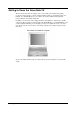
Around the Front of the System The Versa is compact with features on every side. First, look at the front of the system. The following sections describe front features, beginning with the liquid crystal display (LCD) panel. LCD Panel The Versa Note VX comes with a colour LCD panel that you can adjust for a comfortable viewing position. The LCD panel can be a 12.1-inch Super Video Graphics Array (SVGA) colour display, or a 13.3/14.1-inch Extended Graphics Array (XGA).
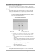
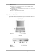
Control panel A – CD Control Buttons or Password Buttons B – Status LEDs C – Email Button D – Internet Button E – Power Button n CD Control Buttons — use to control the CD-ROM drive (stop, reverse, play/pause, and fast forward). Available on some systems. n Password Buttons — set a password or personal identification number for security. Available on some systems. n Status LEDs — keep you informed of your Versa Note VX’s current operating status.
C – Caps Lock Lock n Hard Drive Access — lights when the Versa Note VX accesses the hard disk drive, CD-ROM drive or DVD-ROM drive. n Diskette Drive Access — lights when the Versa Note VX writes data to or retrieves data from the diskette drive. n Caps Lock — lights when caps lock is in effect. n Scroll Lock — lights when scroll lock is in effect. n Num Lock — lights when Num Lock mode is active. Keyboard Panel and Base Unit The Versa Note VX keyboard panel and base unit contain the following features.
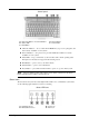
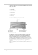
n Keyboard — standard QWERTY-key layout. (Models shipped outside of the U.S. are equipped with country-specific keyboard layouts.) The keyboard is equipped with many features. These include: Function keys Windows keys Cursor control keys Typewriter keys Numeric keypad Control keys. Key features and operations are described after the figure.
Fn-F4 — Sets standby power management mode on, in Windows 95. In Windows 95, press any key to resume from Standby mode. No function when Windows 98 configured for Advanced Configuration and Power Interface (ACPI). In Windows 98, Standby is equivalent to Windows 95 Suspend mode. To resume from Windows 98 Standby mode, press the Power button. Fn-F6 — Toggles the system beep off and on. Fn-F7 — Toggles between various power management levels in Windows 95.
n Control keys — Ctrl, Alt, Fn, and Shift are controls used in conjunction with other keys to change their functions. To use control keys, press and hold the control key while pressing another key. For example, “Press Ctrl c” means to hold down the Ctrl key and type the letter c. Key combinations work specific to the application you are running. n VersaGlide — works like a standard computer mouse. Simply move your fingertip over the VersaGlide to control the position of the cursor.
n PS/2 Port — Use the standard PS/2 port to connect an external PS/2-style mouse, PS/2-style keyboard, or PS/2 style Numeric Keypad to the system. With an optional Y-adapter cable, you can connect up to two of these devices at the same time. n AC Power Port — Lets you attach the Versa Note VX to the AC power source using the AC adapter that comes with your system. Keep the system connected to AC power whenever possible to keep the battery pack and internal CMOS battery charged.
Right side features A – Battery Bay B – Fan C – PC Card Slots D – TV Out n Battery Bay — Depending upon the model, the battery bay contains a rechargeable Nickel-Metal-Hydride (NiMH) or Lithium-Ion (Li-Ion) battery pack. n Fan — Allows your system to cool properly and maintain a safe operating environment. Do not block the fan while the Versa Note VX is in use. n PC Card Slots — Two PC card slots allow you to insert two Type II PC cards or one Type III PC card in the bottom slot.
n Battery Bay — Equipped with a rechargeable Nickel-Metal-Hydride (NiMH) or (depending on the model) Lithium-Ion (Li-Ion) battery. n Battery Release Latch — Slide the latch to the other end and hold it. While holding the latch, slide the battery bay outwards to remove the battery. n Memory Module Bay Cover — Remove the screw to find two SO-DIMM slots. One is inserted with SDRAM memory board configured by the factory. The other is empty for upgrade use.
YMF752-S Yamaha Audio M38813E4 Mitsubishi Keyboard Controller TIPCI1225 Texas Instruments PCI CardBus Controller 1-12 System Overview
2 System Configuration and Setup n Power Sources for Your Versa Note VX n BIOS Setup n Updating the BIOS n NEC Utilities n Application and Driver CD
Power Sources for Your Versa Note VX The Versa Note VX can be powered using three different sources, making it a truly portable system. Operate your Versa Note VX just about anywhere using one of the following power sources: n the AC adapter connected to an electrical wall outlet (using AC power) n the battery pack n the optional auto adapter (For details about its use, refer to the accessory sheet that ships with the option.
Connecting the AC Adapter Note The AC power cable type that your system uses depends on the country where you are using it. Contact the local dealer to purchase the correct power cable. Connect the AC adapter as follows: 1. Connect the AC adapter cable to the power port on the back of your Versa Note VX. 2. Plug one end of the AC power cable into the AC adapter and the other end into a properly grounded 120- or 240-volt wall outlet.
To prevent accidental battery ignition or explosion, adhere to the following: n Keep the battery away from extreme heat. n Keep metal objects away from the battery terminals to prevent a short circuit. n Make sure the battery is properly installed in the battery bay. n Read the precautions printed on the battery. Low Battery Power When battery power gets low, connect your system to the AC adapter. If an AC adapter is not available, change the battery using the battery replacement procedure.
Replacing the Battery The following symptoms indicate that battery life is nearing an end. Replace batteries that display these symptoms. n Shorter work times. n Discoloration, warping. n Hot to the touch. n Strange odour. Replace the battery pack installed in your Versa Note VX system as follows. Note Use the batteries in the Versa Note VX computer for which they are designed.
4. Insert the new battery as follows: n Locate the alignment groove on the edge of the battery. n Locate the alignment groove inside the battery bay. n Align the grooves on the battery with the grooves in the bay. n Slide the battery into the bay until securely locked into place. Installing the battery 5. Turn over the system. Charging the Battery Charge time depends on whether or not you are using the system.
Battery Precautions To prevent accidental battery ignition, rupture, or explosion, adhere to the following precautions. There is a danger of explosion if the battery is incorrectly replaced. Replace only with the same or equivalent type recommended by the manufacturer. Discard used batteries according to the manufacturer’s instructions. To avoid personal injury and property damage, read these battery precautions on handling, charging, and disposing Li-Ion batteries.
CMOS Battery This battery provides battery backup and prevents data loss in the system’s complementary metal-oxide semiconductor (CMOS) RAM. This memory area contains information on the system’s configuration, for example, date, time, drives, and memory. BIOS Setup Your Versa Note VX computer comes with a hardware program called BIOS Setup that allows you to view and set system parameters. BIOS Setup also allows you to set password features that protect your system from unauthorized use.
Use the up and down arrow keys (located on the lower right corner of the keyboard) to toggle through the BIOS Setup menu items. Looking at Screens BIOS setup screens have three areas as shown next. Advanced CMOS Setup n Parameters — The left side of the screen. This area lists parameters and their current settings. n Available Options and Help — The right side of the screen. This area lists alternate settings and Help text for each parameter. n Key Legend — The bottom right corner of the screen.
Checking/Setting System Parameters The BIOS Setup Utility consists of a number of screens, each representing a specific area of the BIOS. The following tables list the BIOS parameters, their factory default settings, alternate settings, and a description of each setting. See the item-specific help that appears on each Setup screen for more details.
n Time — Sets the time, enter the current hour, minute, and second in hr:/min:/sec, 24- hour format. To set the time use the Tab or arrow keys to move from field to field. Use the PgUp or PgDn key to change the numbers within each field. n Diskette Drive — Designates the drive type for your diskette drive. n Internal Drives — Assigns devices to the internal drives in your system. n Boot Sector Virus Protection — Write protects the boot sector of the hard disk drive to avoid infection by some virus types.
System Security Setup Use the System Security Setup to establish system passwords. System Security Setup Parameter Default Setting Change Supervisor Password Press Enter Change User Password Alternate Setting(s) Press Enter 1 Boot Password Required No Yes Resume Password Required2 No Yes Assign HDD Password Press Enter Internal HDD password Disabled 1 2 Enabled Greyed out until supervisor password is set up. Only active after a password is set up.
In Windows 98, to establish password protection for resuming from Standby or Hibernation modes you must do the following: n Set a Windows password in Control Panel, Password Properties, Change Passwords. n Enable the option “Prompt for password when the computer goes off standby,” in Control Panel, Power Management Properties, Advanced. Hard Disk Drive Passwords Your Versa Note VX allows you to establish password protection for the internal hard disk drive.
Moving the Hard Disk Drive When a password protected HDD is moved from its original system and installed in another system, error messages appear indicating that the drive is locked. Next, the Security Setup screen appears requiring the user to enter the master password to unlock the drive. Highlight the HDD password line and enter the master password, when prompted.
n System Switch — Sets the Power button as a power switch or a sleep button. n Power Management Under AC — Specifies whether to enable power management features when AC power is in use. When AC power is connected to your Versa Note VX system, power management is usually disabled. If you enable this parameter, the system automatically activates the power management profile you set, even when AC power is used. n Power Savings Level — Specifies one of four levels of power management.
n Wake Up from Suspend Alarm/Resume Alarm Time — Allows the alarm to wake up the system from Suspend. Designates the time parameter in five minutes increments. Boot Device Setup Boot Device Setup allows you to define the following functions. Boot Device Setup Parameter Default Setting Alternate Setting(s) Quick Boot Enabled Disabled Silent Boot Enabled Disabled, Black Boot Display Device Simul.
Peripheral Setup The Peripheral Setup menu displays the connection locations between the system and the Input/Output (I/O) ports and lets you specify different port assignments as needed.
Updating the BIOS The BIOS is code transmitted onto your system’s microprocessor, or central processing unit (CPU). As indicated in this chapter, you use the BIOS Setup utility to configure your system’s software and hardware features. Use the BIOS Update Diskette, for your specific model, only, to update your Versa Note VX system BIOS. Note You only need to update the BIOS if significant improvements or fixes to the current system BIOS have been made.
Preparing the BIOS Update Diskette Before using the BIOS update diskette you must make the diskette BIOS flash ready. Refer to the readme.txt file on the diskette before using the diskette. Follow these instructions to prepare the BIOS Update Diskette. 1. Scan your hard drive for any computer viruses. 2. Enable the diskette for write access. 3. Insert the diskette into the diskette drive. 4. Type a:install at the DOS prompt and follow the on-screen instructions. Install.
3 Disassembly and Reassembly n Required Tools and Equipment n Disassembly n Reassembly
Required Tools and Equipment All Versa Note VX corrective maintenance procedures can be performed using the following tools: n Tweezers n Small flat-head screwdriver n Small Phillips screwdrivers (# 1 and # 0) n needle-nose pliers n CPU insertion/extraction tool n 3/16” nut driver n Right-angled dentist style probe. Disassembly This section contains step-by-step disassembly procedures for the system. Reassembly is the reverse of disassembly.
3. Remove the battery as follows: n Locate the battery release latch. n Slide the battery release latch towards the back of the system and hold firmly. n Continue to hold the battery release latch as you slide the battery out of the system. Removing the battery A – Battery Release Latch Memory Module and Switch Settings Use the following steps to remove the memory module and access the switch settings. 1. Power off the system and disconnect any peripheral devices. 2.
4. Locate the memory module slot. 5. To remove a SO-DIMM, press the locking tabs away from the sides of the module until the module pops up. Then, remove the SO-DIMM. Removing the memory module Switch Settings A six-position dip switch is located on the bottom of the system. The switch is accessible by removing the access panel beneath the CD-ROM drive. The following list identifies each switch setting and its function. n Switch 1, Password override — The default setting is “OFF.
Hard Disk Drive To remove the hard disk drive, follow these steps. 1. Locate the drive access panel on the left side of the system. Open the panel using the notch. Opening the panel A – Drive Access Panel 2. B – Notch Remove the screw that secures the hard disk in the system.
3. Slide the hard disk drive out of the system. Removing the disk drive LED/Button Assembly Follow these steps to remove the LED/Button assembly. 1. Open the LCD panel. 2. Locate the LCD hinge covers. Locate and remove the screw caps and screws on the hinge covers.
3. Slide each hinge cover toward the outside edge of the system and remove. Removing the hinge covers A – Hinge Cover 4. Lift the LED/button assembly away from the system. Removing the LED/button assembly A – LED/Button Assembly LCD Panel Use the following steps to remove the LCD panel. 1. Remove the LED/button assembly from the system. 2. Close the LCD panel and turn the system over.
3. Locate and remove the two bottom screws securing the LCD panel to the system. Removing the screws A – Screws 4. Turn the system over and open the LCD panel. 5. Locate and remove the two hinge screws.
6. Locate and remove the two screws securing the LCD panel connector to the main board. Removing the LCD panel screws A – Screws 7. Pull the LCD panel up and away from the system. Keyboard and Heat Plate Follow these steps to remove the keyboard and heat plate. 1. Remove the LCD panel from the system. 2. Partially lift the keyboard up and toward the back of the system to clear the tabs from under the top cover.
3. Lay the keyboard key side down over the back of the system. 4. Locate and completely loosen the four screws securing the heat plate to the system. Do not attempt to remove the screws. Loosening the heat plate screws A – Screws B – Heat Plate 5. Partially lift the heat plate. Disconnect the fan cable from connector P5 of the main board and remove the heat plate. 6. Disconnect the keyboard cable from connector P5 of the I/O board and remove the keyboard.
3. Remove the ten screws on the bottom that secure the top cover to the system. Removing the bottom screws A – Screws 4. Turn the system over. 5. Locate and remove the one screw inside the hard disk drive bay that secures the top cover.
6. Locate and remove the one screw on the top that secures the top cover. Removing the top screw A – Screw 7. Partially lift the top cover. Disconnect the VersaGlide cable from connector P8 on the I/O board. Remove the top cover. Removing the top cover A – VersaGlide Cable VersaGlide Follow these steps to remove the VersaGlide assembly. 1. Remove the LCD panel, keyboard, heat plate, and top cover from the system.
2. Turn the top cover over and locate the three screws securing the VersaGlide. Remove the screws. Removing the VersaGlide screws A – VersaGlide 3. B – Screws Slide the VersaGlide assembly away from the top cover tabs and remove the VersaGlide from the top cover. CD-ROM Drive Use the following steps to remove the CD-ROM drive. 1. Remove the LCD panel, keyboard, heat plate, and top cover from the system. 2. Slide the CD-ROM drive out of the system and away from the connector on the main board.
Audio Board Follow these steps to remove the audio board. 1. Remove the LCD panel, keyboard, heat plate, and top cover from the system. 2. Carefully disconnect the audio board from connector P7 on the main board by lifting the audio board. Disconnecting the audio board A – Audio Board 3. Disconnect the cables from connectors P1 and P2 on the audio board and remove the audio board.
DC/DC Board Use the following steps to remove the DC/DC board. 1. Remove the LCD panel, keyboard, heat plate, and top cover from the system. 2. Carefully disconnect and remove the DC/DC board from connectors P9 and P10 on the main board by lifting the DC/DC board.
I/O Board Follow these steps to remove the I/O board. 1. Remove the LCD panel, keyboard, heat plate, top cover, and audio board from the system. 2. Disconnect the diskette drive cable from connector P6 on the I/O board. 3. Disconnect the CMOS battery from P1 of the I/O board. 4. Carefully disconnect and remove the I/O board from connector P12 on the main board by lifting the I/O board.
CMOS Battery Use the following steps to remove the CMOS battery. 1. Remove the LCD panel, keyboard, heat plate, top cover, audio board, and I/O board from the system. 2. Remove the CMOS battery from the front of the base assembly. It is secured with two-sided tape. Removing the CMOS battery A – CMOS Battery Microphone Follow these steps to remove the microphone. 1. Remove the LCD panel, keyboard, heat plate, top cover, audio board, and I/O board from the system. 2.
Diskette Drive Use the following steps to remove the diskette drive. 1. Remove the LCD panel, keyboard, heat plate, top cover, audio board, and I/O board from the system. 2. Locate and remove the two screws securing the diskette drive to the base assembly. Removing the diskette drive screws A – Screws 3. B – Diskette Drive Lift the diskette drive out of the base assembly. Slightly tilt the drive front side down to slide the drive release button out of the base assembly.
Speakers Follow these steps to remove the speakers. 1. Remove the LCD panel, keyboard, heat plate, top cover, audio board, and I/O board from the system. 2. Slide the speaker up out of the front of the base assembly. There are two speakers. Removing the speaker A – Speaker Kensington Lock Latch Use the following steps to remove the Kensington lock latch. 1. Remove the LCD panel, keyboard, heat plate, and top cover from the system. 2.
Main Board Follow these steps to remove the main board. 1. Remove the LCD panel, keyboard, heat plate, top cover, audio board, I/O board, diskette drive, and Kensington lock latch from the system. 2. Locate and remove the four screws that secure the main board to the base assembly. Use the needle-nose pliers to remove the three hex screws. Removing the main board screws A – Hex Screws B – Screw 3. C – Main Board Lift the main board out of the base assembly.
2. Locate the CPU. Locate and remove two of the CPU stand-offs. Removing the CPU stand-offs A – Stand-offs 3. Locate pin 1 on the CPU (identified by the triangle). Align and place the actuation block of the insertion/extraction tool over pin 1 and the pin diagonally opposite pin 1.
4. Place the push rod into the hole closest to pin 1 of the CPU. To release the CPU, push the rod toward pin 1 until you feel the mechanism unlock. Releasing the CPU 5. Lift the actuation block and the CPU out the system. Only touch the CPU on the sides. Do not touch the top of the die. Pentium III Removal Follow these steps to remove the Pentium III CPU. 1.
Only touch the CPU on the sides. Do not touch the top of the die. PC Card Assembly Follow these steps to remove the PC card assembly. 1. Remove the LCD panel, keyboard, heat plate, top cover, audio board, I/O board, diskette drive, Kensington lock latch, and main board from the system. 2. Turn the main board over. 3. Remove both memory modules, if present. 4. Locate and remove the four screws that secure the PC card assembly to the main board. Removing the PC card screws A – Screws 5.
4 System Board Layout n Audio Board n DC/DC Board n I/O Board n Main Board
This following figures show the system boards and connector locations.
I/O Board A – Connector P5 B – Connector P3 (back side) C – Connector P6 D – Connector P2 E – Connector P1 F – Connector P8 Main Board A – Connector P17 B – Connector P15 C – Connector P10 D – Connector P8 E – Connector P2 F – Connector P5 G – Connector P4 H – Connector P7 I – Connector P9 J – Connector P12 System Board Layout 4-3
5 Preventive Maintenance n Cleaning the Notebook Exterior n Cleaning the Notebook Interior n Protecting the Disk Drive n Handling the Battery Pack n Maintaining the LCD Quality
Preventive maintenance is limited to cleaning the plastic case, the keyboard, the display screen, and the diskette drive heads, as required. Note Remove the battery and disconnect the AC adapter before performing any maintenance. Voltage is present inside the system unit and LCD even after the system is turned off. Cleaning the Notebook Exterior Use the steps below to clean the outer surface of the system. 1. Power off the system and remove the battery pack. Unplug all cables connected to the system.
n Use hard disk maintenance program like DEFRAG under DOS, or acquire Norton Utilities SPEEDISK programs. These programs reorganize your hard disk by eliminating fragmentation and improve the hard disk access time. Handling the Battery Pack The battery pack furnished with the computer requires reasonable care and handling to ensure efficient operation and maximum life. Periodically inspect the battery terminals and the batteries for evidence of corrosion and oxide build-up.
6 Troubleshooting n Quick Troubleshooting n Helpful Questions
Quick Troubleshooting This section summarizes problems that may develop during system operation and lists suggested corrective actions. Quick Troubleshooting Problem or Symptoms Corrective Actions No power Check that the AC adapter is plugged into the power port of the notebook. Also, check that the AC adapter is plugged into a properly grounded AC power outlet. If using the battery as the main power source, check if the battery pack is the correct type, charged properly, and is inserted correctly.
Quick Troubleshooting Problem or Symptoms Corrective Actions Diskette drive does not work Check if the diskette drive option is not installed in BIOS Setup. Check if the diskette drive cable is connected properly. Check that the diskette is not faulty. Replace the diskette drive. Replace the main board. Hard disk drive malfunction Check if the hard disk drive is set properly in BIOS Setup. Check the connection. Check if the disk drive is working properly. If not, replace the drive.
Quick Troubleshooting Problem or Symptoms Corrective Actions Serial device does not work Check if the serial port is set to “Auto” in BIOS Setup. Check if the serial device is connected properly. Check if the mouse driver is installed properly. Replace the serial device. Check the I/O controller chip for any cold or loose soldering. Replace the main board. Parallel device does not work Check if the parallel port is set to “Auto” in BIOS Setup. Check if all connections are properly set.
Helpful Questions Here are some helpful questions to ask when troubleshooting the notebook: n Is there any external power source connected to the computer? n Is the battery fully charged? n Is the computer turned on and the Power LED activated? n Is the LCD display switched to the external monitor? n Are all cables and devices connected properly and securely? n Are all needed device drivers installed properly? n Is the Suspend Mode activated? Press any key or press the Power/Sleep button to pow
7 Specifications n System Components n Connector Locations n Memory Map n Interrupt Controllers
System Components The following system component specifications are standard except where noted. System Processor Depending on the model: n Intel Celeron 400 MHz, 433 MHz, or 466 MHz n Intel Pentium II 366 MHz n Intel Pentium III 450 MHz or 500 MHz Random Access Memory (RAM) n Standard Main Memory — 64 MB high-speed interleaved access n Optional Expansion — 1 SO-DIMM slot Expandable in 64-MB or 128-MB increments Maximum 256 MB total n Video RAM — 4.
Main Battery n Types: Lithium-Ion (Li-Ion), eight cell – Output Voltage – 14.4v – Capacity – 3,600 mAh n Recharging Time Lithium-Ion (Li-Ion): Approximately 3.5 hours when system is not in use; approximately 4 hours when system is in use. Card Slots Two 32-bit card slots for two Type II or one Type III PC card, 5 V or 3.3 V interface LCD Display n Panel (depending on the model): 12.1-inch Thin Film Transistor (TFT) cold-cathode fluorescent tube (CCFT) backlit Super VGA colour 13.3/14.
n Capacity (depending on the model) 6.0-GB, 12-GB, or larger hard disk drive CD-ROM Drive n Thin-type CD-ROM Pack n Access Time — 24X n Interface — IDE (ATAPI) n Photo CD Compatibility — Multisession Photo CD, Single Session Photo CD, Video CD, CS-I, CD-I Ready, CD-G and CD-Plus Mini-PCI Modem n K56 Flex compatible n V.34 extended rate protocol n V.
Dimensions System n Width — 12 in. (307 mm) n Depth — 9.9 in. (252 mm) n Height — 1.6 in. (40 mm) (max 44 mm) Weight n 6.6 lbs. (3.0 kg) 12.1-inch LCD n 6.8 lbs. (3.1 kg) 13.3-inch LCD n 7.0 lbs. (3.2 kg) 14.
Connector Locations The following table shows the system’s connector locations.
Memory Map The system supports system and video shadowing, both controlled through complementary metal oxide semiconductor (CMOS). The system supports BIOS as a cacheable area with write protection. The following table shows the system’s memory map.
Interrupt Controllers The following table shows default interrupt level assignments 0 through 15.
Glossary A applications programs Software designed to perform specific functions, like solving business or mathematical problems. AC Adapter A device that connects an NEC Versa portable computer and an AC wall outlet to provide AC power for running the system or recharging the battery. B base RAM Area of system memory between 0 and 640 kilobytes available to the user for operating system and application programs. BIOS Basic Input Output System.
C clock Electronic timer used to synchronize computer operations. CMOS Complementary Metal Oxide Semiconductor. A chip that contains nonvolatile memory in the NEC Versa. CMOS is backed up by an internal lithium battery that preserves clock/calendar data and system configuration parameters stored in CMOS. cold boot Process of starting up the computer by turning on the power. If power is already on, the process means to turn off the computer and turn it on again. A cold boot reinitializes all devices.
H hard disk A rigid magnetic storage device that provides fast access to stored data. hardware The electrical and mechanical parts from which a computer is made. hertz (Hz) A unit of frequency equal to one cycle per second. hot key Combination of two or three keys (such as Ctrl-Alt-Del) that you press simultaneously for a particular function. I input/output (I/O) The process of transferring data between the computer and external devices. IDE Intelligent Drive Electronics.
M megabyte (MB) 1,048,576 bytes. memory Electronic storage area in a computer that retains information and programs. A computer has two types of memory — read-only memory (ROM) and random access memory (RAM). menu A video display of programs or options. microprocessor A semiconductor central processing unit that is the principal component of a microcomputer. Usually contained on a single chip that includes an arithmetic logic unit, control logic, and control-memory unit.
parameter A characteristic of a device or system. password A string of characters that the user must enter before the system allows access or system privileges. PCMCIA A credit card sized peripheral interface standard for portable devices. Types of PCMCIA cards currently offered by major vendors include fax/modems, LAN, storage cards, and wireless communications devices. peripheral Input or output device not under direct computer control. A printer is a peripheral device. pixels Picture elements.
resolution The degree of screen image clarity. Video display resolution is determined by the number of pixels on the screen. Resolution is usually specified in pixels by scan lines, for example, 640 by 480. See pixels. RS-232C Standard interface for serial devices. S scanner An optical device that reads printed material and converts it to a computer screen image. serial interface An interface that communicates information one bit at a time. serial printer A printer with a serial interface.
W warm boot Process of resetting the computer without turning off the power through keyboard input (pressing Ctrl, Alt, and Del keys simultaneously) or the reset button. The system returns to an initial or arbitrarily selected condition. write To record or store information to a storage device.
Index A AC adapter specifications, 9-5 using, 2-2 Application and driver CD installing, 2-22 Applications and drivers CD launching, 2-21 Applications and Drivers CD using, 2-21 B Backup system disk, 6-2 Battery battery life, 2-4 charging, 2-6 handling, 2-4 recharging precautions, 2-7 refresh, 2-17 specifications, 9-3 when to change, 2-5 Battery pack, 1-11 precautions, 2-7 BBS, 8-3 BIOS language setting, 2-17 BIOS setup, 2-8 BIOS setup utility other options, 2-17 C Calendar clock, 9-2 CD-ROM drive, 1-12 remo
specifications, 9-4 N NEC CSD bulletin board, 8-3 Customer Assistance Center, 8-5 email/fax, 8-3 FTP site, 8-3 support services, 8-4 web site, 8-2 NEC Customize, 2-20 NEC customize utility using, 2-20 NEC utilities, 2-20 NEC Versa disassembly sequence, 3-2 Numeric keys, 1-8 O Operating environment, 9-5 P Panel brightness, 2-15 Parallel port, 2-17 Parts list, 5-3 Password establishing, 2-12 hard disk drive, 2-12 supervisor, 2-12 user, 2-12 PC card slots, 9-3 Pentium II microprocessor, 1-2 Pentium III micropr