
User Manual


Packet Power™ Wireless Smart DC Monitoring System Manual
Copyright 2015 © Packet Power, LLC.
4
P5C-DCX1 chart for input voltage specifications and make sure that the monitor matches
the voltage level of the DC bus.
Each monitor will report current and an Amp Hour (Ah) total for it’s circuit. An unlimited
number of current monitors can be used in an network as long as sufficient Gateway
capacity is available.
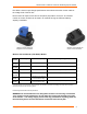
Wireless Current Monitor (P5C-DCX1) Models
Product
Number
CT Range Max. Current (A DC) Input
V
oltage Range (V DC)
P5C-
DCIL65A
0-65A 65 A 5-24V (max. 36V)
P5C-
DCIH65A
0-65A 65 A 48V (max. 65V)
P5C-
DCIL35A
0-35A 35 A 5-24V (max. 36V)
P5C-
DCIH35A
0-35A 35 A 48V (max. 65V)
P5C-
DCEL
External CT
Dependent on the external
current transducer rating.
1
5-24V (max. 36V)
P5C-
DCEH
External CT
Dependent on the external
current transducer rating.
1
48V (max. 65V)
1: Consult external CT specification sheets for details. All external CTs provide a low voltage DC output with no potential
overcurrent exposure to the monitoring device.
Power Usage is less than 0.25 W per device.
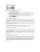
WARNING: DC Current Monitors are designed to monitor current using via inductive
“non contact’ current transducers. Do not apply DC current path directly to any part
of the monitor. The voltage supply sensors are only provided for acquiring power for
the monitoring device and not intended to sustain the load current path.
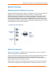
Wireless Current Monitor for
remote current transducer
Wireless Current Monitor for
integrated current transducer