7-STAGE AUTOMATIC BATTERY CHARGER MCU CONTROLLED & HIGH FREQENCY SWITCHMODE Instruction Manual Please read user manual carefully before use.
1. WARNING ◆ Explosive gases may escape from the battery during charging. Prevent flames and sparks. Provide adequate ventilation. ◆ Before charging, read the instructions. ◆ For indoor use. Do not expose to rain. ◆ For charging 12 Volt or 24 Volt lead acid batteries ONLY. ◆ Disconnect the 110V/220-240V AC mains supply before making or breaking the connections to the battery. ◆ The battery charger must be plugged into an earthed socket-outlet.
Desulphation The Desulphation stage may break down sulphation that occurs in batteries that have been left flat for extended periods of time, returning them back to full charge. sulphation occurs when lead-sulphate hardens and clogs up the battery cells. Soft Start A preliminary charge processes that gently introduces power to the battery. This protects the battery and increases battery life.
Battery Test An automatic battery test is conducted immediately after the absorption stage. The test monitors the voltage for 90 seconds to determine if the charge was successful. ◆12V charger If the voltage is below 13.2 volts (fail), the charger will initiate the Recondition stage. ◆12V charger If the voltage is above 13.2 volts (pass), the charger will proceed to the final stage: Float. ◆24V charger If the voltage is below 26.4 volts (fail), the charger will initiate the Recondition stage.
3. SWITCHMODE TECHNOLOGY Using the latest technology in battery chargers, switch mode chargers convert 110V/220-240V AC power to 12V/24V DC power using electronic components unlike traditional battery chargers that rely on heavy transformers. This allows the charger to be light weight and compact without sacrificing on performance. 4.
5. PRODUCT OVERVIEW The 7-stage automatic charging consists of the following components: LED Charge Status Display Indicates Power, Charging and Fully Charged Switch on/off Thermostatically controlled cooling fan 5.
6. CHARGE STATUS INDICATOR The CHARGING and FULLY CHARGED LEDs will illuminate and flash in various patterns to indicate the different stages of charging. See below for flash patterns. Red LED Green LED Red LED Yell LED ●Power On ●Charging ●Fully Charged ●Fault Power Off Power On Charging 1. Desulphation 2. Soft Start 3. Bulk 4. Absorption 5. Battery Test 6. Recondition 7.
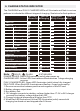
7. SPECIFICATIONS P/No. MBC 1204 Charger type 7-Stage automatic 7-Stage automatic 7-Stage automatic 7-Stage automatic Input Voltage MBC 1205 MBC 1207 220-240V~, 50/60Hz MBC 1210 110V~, 50/60Hz Input Power 123W 154W 215W 307W Output Voltage 12V DC 12V DC 12V DC 12V DC Output Current 4A 5A 7A 10A Minimum Start Voltage 2V 2V 2V 2V Current Fuse Rating 250VAC, T3.15A 250VAC, T3.15A 250VAC, T3.15A 250VAC, T3.15A Current Fuse Rating250VAC, T3.15A 250VAC, T3.15A 250VAC, T3.
8. SPECIFICATIONS P/No. MBC 1212 Charger type 7-Stage automatic 7-Stage automatic 7-Stage automatic Input Voltage MBC 1215 220-240V~, 50/60Hz MBC 1220 110V~, 50/60Hz Input Power 332W 415W 554W Output Voltage 12V DC 12V DC 12V DC Output Current 12A 15A 20A Minimum Start Voltage 2V 2V 2V Current Fuse Rating 250VAC, T3.15A 250VAC, T5A 250VAC, T3.15A Current Fuse Rating250VAC, T3.15A 250VAC, T3.15A 250VAC, T3.15A 250VAC, T3.
9. SPECIFICATIONS P/No. MBC 2405 Charger type 7-Stage automatic 7-Stage automatic Input Voltage MBC 2410 220-240V~, 50/60Hz Input Power 296W Output Voltage 24V DC 24V DC Output Current 5A 10A 110V~, 50/60Hz 547W Minimum Start Voltage 4V 4V Current Fuse Rating 250VAC, T5A 250VAC, T3.15A Current Fuse Rating250VAC, T3.15A 250VAC, T3.15A 250VAC, T3.15A Pulse charge up to 22V Desulphation Half the rated set current up to 24V Soft Start Bulk 5A (Up to 28.8V) 10A (Up to 28.
10. CHARGING INSTRUCTIONS STEP 1 CHECK THE ELECTROLYTE LEVEL Prior to charging the battery, remove the vent caps and check the electrolyte level (not required on sealed & maintenance free batteries). The electrolyte should be 6mm (1/4") above the battery's plates. If low, top up with distilled water to the correct level and refit the vent caps. STEP 2A CONNECTION OUT OF THE VEHICLE Connect the RED lead (battery clip) from the charger to the Positive (+) battery post.
11. Negatively earthed (most vehicles) Connect the RED lead (battery clip) from the charger to the Positive (+) battery terminal. Connect the BLACK lead (battery clip) from the charger to the vehicle's chassis away from the fuel line or moving parts. RED BLACK Connection in vehicle (negatively earthed) 12. Positively earthed Connect the BLACK lead (battery clip) from the charger to the Negative (-) battery terminal.
. CHASSIS EARTHING The chassis earthing lug should be connected to an earting point which will be depending on where the battery charger is installed. In a vehicle, connect the chassis ground lug to the chassis of the vehicle. In a boat, connect to the boat's grounding systems. In a fixed location, connect to earth. 7-STAGE AUTOMATIC CHARGING P/No.: MBC 1210 INPUT: 220-240V AC, 50/60Hz, 307W OUTPUT: 12V DC, 10,000mA FUSE: T3.
. MOUNTING INSTRUCTIONS 7-stage chargers are designed for indoor, out of weather use only. Ensure that both charger and battery are in a well-ventilated space during charging. The battery charger end plates include a mounting flange for easy mounting. If permanently fixed the charger should be mounted to a suitable horizontal or vertical panel, with at least 10cm clearance from the end plates to provide adequate ventilation for the cooling fan. 3.5mm mounting hole 15.
Connection: 1. Cut off the supplied battery clips; ensure you leave sufficient cable to reach the battery terminals. (DO NOT extend the battery charger DC cables, as the added voltage drop will cause incorrect charging). 2. Fit a ring terminal to the BLACK Negative (-) wire. 3. Connect the inline fuse to the RED Positive (+) wire. 4. Connect a ring terminal to the other end of the inline fuse. 5. Connect the RED lead (with inline fuse and ring terminal) to the Positive (+) battery post. 6.
. ADJUSTABLE CHARGE RATES: 12 VOLT BATTERY CHARGE RATE BATTERY SIZE (12V) Deep Cycle (AH) Charger Time (Hours) 4Amp 30-80 7-24 5Amp 35-100 7-24 7Amp 50-140 7-24 10Amp 70-200 7-24 12Amp 80-250 7-24 15Amp 100-300 7-24 20Amp 134-400 7-24 17.
18. FAULT CODES There are error codes that may be displayed. These will be displayed in the following way: Error Code Charging Fully Charged Fault Cause LED LED LED Remedy Polarity Reverse / Output Short Check clips are not Short circuit or touching each other reverse OR Check the clips are connection of the correctly connected to clips the battery. Non Battery Link Non battery link Faulty Battery (Bulk Led) Please choose the right battery type for connection.
FREQUENTLY ASKED QUESTIONS Q. How do I know if the battery is charged A. The charger's FULLY CHARGED LED will illuminate (solid). Alternatively use a Battery. Hydrometer A reading of 1.250 or more in each cell indicates a fully charged battery. Q. I have connected the charger properly but the 'CHARGING LED' does not come on A. In some cases batteries can be flattened to the point where they have very little or no voltage.
CAUTION ALWAYS PLACE THE BATTERY CHARGER IN AN ENVIRONMENT WHICH IS: A. WELL VENTILATED. B. NOT EXPOSED TO DIRECT SUNLIGHT OR HEAT SOURCE. C. OUT OF REACH FROM CHILDREN. D. AWAY FROM WATER / MOISTURE, OIL OR GREASE. E. AWAY FROM ANY FLAMMABLE SUBSTANCE. F. SECURE NO RISK OF FALLING.