P/N 60502 & 60505 1994/1995 GM LT1 FUEL INJECTION WIRE HARNESS INSTALLATION INSTRUCTIONS Manual P/N 90517 Copyright © May 2002 PAINLESS PERFORMANCE PRODUCTS 2501 Ludelle Street - Fort Worth, Texas 76105-1036 - (817) 244-6898 E-Mail: tech@painlessperformance.com Web: painless@painlessperformance.
We have attempted to provide you with as accurate instructions as possible, and are always concerned about corrections or improvements that can be made. If you have found any errors or omissions, or if you simply have comments or suggestions concerning these instructions, please write us at the address on the cover and let us know about them. Or, better yet, send us a fax at (817) 244-4024 or e-mail us at painless@painlessperformance.com. We sincerely appreciate your business.
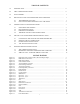
TABLE OF CONTENTS 1.0 INTRODUCTION.......................................................................................................................... ii 2.0 ABOUT THESE INSTRUCTIONS............................................................................................... ii 3.0 TOOLS NEEDED.......................................................................................................................... 1 4.0 PRE-INSTALLATION AND HARNESS ROUTING GUIDELINES.......................
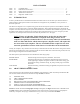
LIST OF TABLES Table Table Table Table Table 4.1 6.1 6.2 6.3 7.1 Compatible Parts.............................................................................................................. Dash Section Connections................................................................................................ Engine Section Connections............................................................................................. Tail Section Connections.....................................................
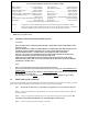
3.0 TOOLS NEEDED In addition to your regular tools, you will need, at least, the following: Crimping tool NOTE: Wire stripper Continuity tester CAUTION: USE A QUALITY TOOL TO AVOID OVER-CRIMPING. DO NOT USE A TEST LIGHT TO TEST THE COMPUTER OR SENSOR WIRING OR YOU WILL DAMAGE THE COMPUTER. Electric drill 1 5/8" Hole saw (for the rubber grommet in the firewall) 4.
To keep the check engine light from coming on you will need to plug in a canister purge solenoid and air pump relay to the wires in the dash section. (The computer looks for signals from these controls and does not care if the actual devices are installed.) 4.2 YOU SHOULD GET TO KNOW THE PARTICULAR ENGINE YOU ARE USING: NOTE: The 94 & 95 LT1 engine has two oxygen sensors, one on the right side and one on the left side of the engine. This system has four rectangular connectors at the computer.
LT1 Fuel Injection Harness (94 & 95) Part # 60502 or 60505 Main Computer............................Service#16188051 EGR. Solenoid................................ Delco# 214-396 Brake Switch.....................................GM# 25524845 Gear Indicator Switch..................GM# 15705308 or Intake Air Temperature.....................GM# 12110319 Delco #D2286A Ignition Module.............................Delco# D-1986-A MAP Sensor ....................................GM# 16137039 Fuel Pump Relay...
5.2 ROUGH INSTALLATION CAUTION: Note: Make no wire connections or permanent mounting of any kind at this time. 5.2.1 5.2.2 Position the computer and sensors in their intend locations. Drill a 1-5/8" hole for the firewall grommet near the computer for the engine group and tail section to pass through. Route the engine group and tail section through the hole. Push the grommet (already installed on the harness) into the hole until it is seated. Route the dash group over to the driver's side of the car.
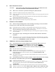
CAUTION: BE SURE THE IGNITION IS OFF WHEN YOU RECONNECT THE BATTERY OR YOU WILL DAMAGE THE COMPUTER. 6.0 GM 94 & 95 LT1 SYSTEM WIRE HARNESS INSTALLATION INSTRUCTIONS 6.1 CONTENTS OF THE 60502 OR 60505 WIRE HARNESS KIT Take inventory to see that you have everything you are supposed to have in this kit. If anything is missing, contact the dealer where you obtained the kit or contact Painless Performance at (817) 244-6898.
WHEN THE KEY IS IN THE START AND RUN POSITION. This is the power wire for the fuel injection harness. If the pink wire is connected correctly, the check engine light will come on when the ignition is "ON or START". D. Locate the Orn/Blk and Blk/Wht wires in the dash group. These two wires are for the Park/Neutral INDICATOR Switch, NOT the Neutral Safety Switch. If you have a GM column then you can use the combination switch P/N 15679680 and wire it as described in paragraph 2 or 3 below.
FIGURE 6.3 Brake Switch Relay FIGURE 6.
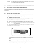
F. If you are using the recommended brake switch then you will wire it according to Figure 6.2. The pink wire to the back of the switch in the illustration is the wire that has power on it whether or not the brake is being applied. CAUTION: G. FAILURE TO WIRE THIS SWITCH CORRECTLY WILL RESULT IN A DANGEROUS SITUATION ON THE VEHICLE. If your vehicle has a pressure type brake switch, you may use a relay as shown in Figure 6.3.
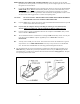
FIGURE 6.8 Fuel Pump Relay Connector FIGURE 6.7 Air Pump Connection 6.3 ENGINE GROUP INSTALLATION The engine group is designed to be separated into left side (driver) and right side (passenger) sections. Each side is tie-wrapped separately, BUT NOT LABELED. The right side of the engine has the connectors for the idle air control, throttle position sensor, distributor, and map sensor, all of which ARE labeled.
6.3.
FIGURE 6.11 Oxygen Sensor FIGURE 6.12 MAP Sensor FIGURE 6.13 Injectors 1, 3, 5, 7 FIGURE 6.14 Injectors 2, 4, 6, 8 FIGURE 6.16 IAC FIGURE 6.
FIGURE 6.18 Distributor i FIGURE 6.17 MAF Sensor FIGURE 6.19 Ignition Module FIGURE 6.20 Coil FIGURE 6.21 ECT Sensor FIGURE 6.
6.4 TAIL SECTION INSTALLATION 6.4.1 Locate the tail section that you earlier separated from the engine group. Begin routing it towards the rear of the vehicle. Be sure to avoid all sharp edges, moving or hot parts, or anything else that may damage the harness. 6.4.2 If you ARE using the 4L60E transmission, route the 13-position connector to the transmission and attach it. 6.4.3 If you ARE NOT using the 4L60E transmission, tape up the connector and store it in the harness. 6.4.
FIGURE 7.1 Fuse Identification 7.1 THE "CHECK ENGINE" LIGHT Normally, the "check engine" light should come on when the ignition is turned on, then go out a few moments after the engine starts running. If it reappears, or stays on while the engine is running, the computer has detected a problem and a trouble code has been set. 7.2 RETRIEVING TROUBLE CODES FROM THE COMPUTER The chart below shows the type of ALDL test connector each vehicle came with from the factory.
7.2.
DTC 83 = Reverse Inhibit System (Manual Transmission) DTC 83 = TCC PWM Solenoid Circuit Fault (Automatic Transmission) DTC 84 = Automatic Transmission 3-2 Control Solenoid Circuit DTC 84 = Skip Shift Solenoid Circuit (Manual Transmission) DTC 85 = Transmission TCC Stuck "ON" DTC 90 = Transmission TCC Solenoid Circuit (Manual Transmission) DTC 91 = Skip Shift Lamp Circuit DTC 97 = VSS Output Circuit DTC 99 = Tach Output Circuit TABLE 7.1 Diagnostic Trouble Codes 7.
Painless Performance Limited Warranty and Return Policy Chassis harnesses and fuel injection harnesses are covered under a lifetime warranty. All other products manufactured and/or sold by Painless Performance are warranted to the original purchaser to be free from defects in material and workmanship under normal use. Painless Performance will repair or replace defective products without charge during the first 12 months from the purchase date.