
User's Manual

CAUTION: BE SURE THE IGNITION IS OFF WHEN YOU RECONNECT THE BATTERY
OR YOU WILL DAMAGE THE COMPUTER.
6.0 GM 97 - 99 LS1 SYSTEM WIRE HARNESS INSTALLATION INSTRUCTIONS
6.1 CONTENTS OF THE 60506-7 & 60508-9 WIRE HARNESS KIT
Take inventory to see that you have everything you are supposed to have in this kit. If anything is missing, contact
the dealer where you obtained the kit or contact Painless Performance at (817) 244-6898. The kit should contain the
following items:
~ The main wire harness with the connectors already on the ends of most of the wires.
~ Fuel Injection Installation Instructions P/N 90520 (This Booklet).
~ Vehicle anti-theft (VATS) bypass module.
~ 4” & 7” tie wraps.
6.2 SPECIFIC CIRCUIT CONNECTIONS
Note: If you have not already done so, read sections 4.0 and 5.0 of these instructions and think
through the installation of the harness before securing or cutting any wires.
6.2.1 DASH SECTION INSTALLATION
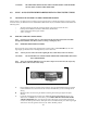
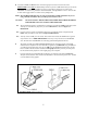
The wires in this group consist of the diagnostic link connector (DLC) (SEE FIGURE 6.1), the check
engine light (pre-mounted into a mounting bracket), and 14 other wires.
Note: You may need to connect the check engine light wires to their mates in the wire harness.
CAUTION: DO NOT MAKE ANY CONNECTIONS WHILE THE COMPUTER IS PLUGGED
INTO THE HARNESS.
Note: Wire color (Example: Blk/Wht) is one wire with a stripe. The second color (the stripe) may
not be bold. Observe all two-color wires closely.
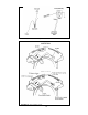
A. Find a suitable location to mount the DLC connector (using the bracket that the light is mounted
in) that will allow access to the front of the connector and still allow you to see the light while
driving.
B. Mount the DLC connector using the bracket containing the check engine light in the place
selected.
C. Locate the pink ignition hot activation wire, labeled FUSE BLOCK IGNITION (18 Ga.) and
attach it to a 12V fused source where there is power WHEN THE KEY IS IN THE START
AND RUN POSITION. This wire activates the relays that supply power to all the ignition hot
circuits in the fuel injection harness. If the pink wire is connected correctly, the check engine light
will come on when the ignition switch is in the "ON or START" position.
6
FIGURE 6.1 DLC Connector & Check Engine Light