P/N 60506 & 60507 1997-98 GM LS1 FUEL INJECTION WIRE HARNESS INSTALLATION INSTRUCTIONS P/N 60508 & 60509 1999-02 GM LS1 FUEL INJECTION WIRE HARNESS INSTALLATION INSTRUCTIONS Manual P/N 90520 Sixth Edition November 17, 2005 Copyright © Oct.
1.0 2.0 3.0 4.0 5.0 6.0 7.0 INTRODUCTION.......................................................................................................................... ABOUT THESE INSTRUCTIONS............................................................................................... TOOLS NEEDED.......................................................................................................................... PRE-INSTALLATION AND HARNESS ROUTING GUIDELINES...........................................
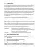
1.0 INTRODUCTION We at Painless Performance Products believe you have purchased the most up-to-date and easiest to install automotive fuel injection harness on the market. All components to this harness are new. All harnesses are tested for faults before they leave the factory floor. This harness is designed for easy installation, even if you have no electrical experience.
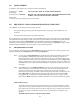
3.0 TOOLS NEEDED In addition to your regular tools, you will need, at least, the following: Crimping tool NOTE: Wire stripper Continuity tester CAUTION: USE A QUALITY TOOL TO AVOID OVER-CRIMPING. DO NOT USE A TEST LIGHT TO TEST THE COMPUTER OR SENSOR WIRING. YOU WILL DAMAGE THE COMPUTER. Electric drill 1 5/8" Hole saw (for the rubber grommet in the firewall) 4.
4.2 YOU SHOULD GET TO KNOW THE PARTICULAR ENGINE YOU ARE USING: NOTE: The 1997-02 LS1 engine had four oxygen sensors from the factory. We have included provisions for only two oxygen sensors, which include one on the driver side and one on the passenger side of the engine. We have removed the two rear oxygen sensors since they originally where behind the catalytic converters and most people don’t want to run more than two oxygen sensors. This system has two rectangular connectors at the computer. 4.2.
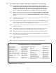
LS1 Fuel Injection Harness (99 - 02) Part # 60508 & 60509 Main Computer…………………Service #9354896 Service #12200411 Fuel Pump Relay………………..Delco #15-8240 Brake Switch…………………….Delco #D850A Gear Indicator Switch…………...Delco #D2286A Intake Air Temperature………….GM #12160244 Delco #213-243 MAF Sensor……………………..GM #25179711 Engine Coolant Temperature……GM #5326388 Delco #213-953 Oxygen Sensor (Pass. Side)……..GM #25312196 Delco #AFS97 Oxygen Sensor (Drvr. Side)……..
5.2 ROUGH INSTALLATION CAUTION: Note: Make no wire connections or permanent mounting of any kind at this time. 5.2.1 5.2.2 Position the computer and sensors in their intend locations. Drill a 1-5/8" hole for the firewall grommet near the computer for the engine group and tail section to pass through. Route the engine group and tail section through the hole. Push the grommet (already installed on the harness) into the hole until it is seated. Route the dash group over to the driver's side of the car.
CAUTION: BE SURE THE IGNITION IS OFF WHEN YOU RECONNECT THE BATTERY OR YOU WILL DAMAGE THE COMPUTER. 6.0 GM 97 - 99 LS1 SYSTEM WIRE HARNESS INSTALLATION INSTRUCTIONS 6.1 CONTENTS OF THE 60506-7 & 60508-9 WIRE HARNESS KIT Take inventory to see that you have everything you are supposed to have in this kit. If anything is missing, contact the dealer where you obtained the kit or contact Painless Performance at (817) 244-6898. The kit should contain the following items: ~ ~ ~ ~ 6.
D. Locate the Orn/Blk and Blk/Wht wires in the dash group. These two wires are for the Gear INDICATOR Switch, NOT the Neutral Safety Switch. If you have a GM column then you can use the combination switch Delco P/N D2286A and wire it as described in paragraph 2 or 3 below. The ORN/BLK wire needs to be grounded in "Park and Neutral" and ungrounded in "Drive". This can also be done with a toggle switch or a switch on the parking brake.
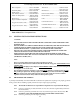
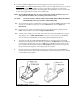
FIGURE 6.3 Brake Switch Relay FIGURE 6.
CAUTION: G. FAILURE TO WIRE THIS SWITCH CORRECTLY WILL RESULT IN A DANGEROUS SITUATION ON THE VEHICLE. If your vehicle has a pressure type brake switch, you may use a relay as shown in Figure 6.3. The relay must be a SPDT Relay and wired correctly or it could result in a dangerous situation with the vehicle. The torque converter may not unlock. The wire labeled FUEL TEST is a test point for the fuel pump. After the vehicle has been wired and tested OK, tape off this wire and store it in the harness. H.
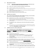
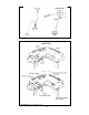
Air Solenoid Relay Air Pump Relay FIGURE 6.6 Canister Purge Solenoid FIGURE 6.5 Air Pump & Air Sol. Relays Fuel Tank Air Pump Original location of the air pump in the `98 Camaro. This is the original location of the canister vent solenoid in the `98 Camaro. FIGURE 6.8 Air Pump Connection FIGURE 6.7 Canister Vent Solenoid Air Bleed Solenoid Original location of the air bleed solenoid in the `98 Camaro. FIGURE 6.9 Air Bleed Solenoid 6.3 FIGURE 6.
6.3.1 6.3.2 6.3.3 6.3.4 Before you connect any wires, separate the tail section from the engine group and place it out of the way. Connect the two ring terminals labeled STARTER B+ with Red wires to the large battery terminal on the starter solenoid. Locate the three large ring terminals with Black and Blk/Wht wires and ground them to the engine. Using Figure 6.11-6.25, and the specific connections indicated in Table 6.2A or 6.2B, connect the wiring as directed.
WIRE COLOR # OF POSITIONS IN CONNECTOR Blue, Lt.Blue Tan/White, Purple/White, Black, Pink Tan, Purple, Black, Pink Orange/Black, Lt.Green, Gray Brown/White, Red, Pink/Black Blue/White, Yellow/Black, Lt.Green Pink, Black Pink, Lt.Green/Black Pink, Pink/Black Pink, Lt.Blue/Black Pink, Black/White Pink, Yellow/Black Pink, Red/Black Pink, Blue/White Blue, Black, Gray Yellow, Black/White, Pink Black, Yellow Purple, Tan Lt.Green/Black, Lt.Blue/Black, Lt.Blue/White, Lt.Green/White Purple, Red, Green, Lt.
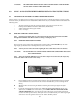
FIGURE 6.13 O2 Sensor FIGURE 6.14 MAP Sensor FIGURE 6.16 Crank Position Sensor FIGURE 6.15 Cam Position Sensor INJ #1 INJ #3 INJ #5 INJ #8 INJ #7 FIGURE 6.17 Injectors 1, 3, 5, 7 INJ #6 INJ #4 FIGURE 6.
FIGURE 6.19 TPS Sensor FIGURE 6.20 IAC FIGURE 6.21 MAF Sensor FIGURE 6.22 Driver Side Coil Connector FIGURE 6.23 Passenger Side Coil Connector FIGURE 6.
FIGURE 6.25 IAT Sensor 6.4 TAIL SECTION INSTALLATION 6.4.1 Locate the tail section that you earlier separated from the engine group. Begin routing it towards the rear of the vehicle. Be sure to avoid all sharp edges, moving or hot parts, or anything else that may damage the harness. 6.4.2 If you ARE using the 4L60E transmission, route the 13-position connector to the transmission and attach it. Tape up the reverse lockout and skip shift solenoid connectors and store them in the harness. 6.4.
FIGURE 6.26 VSS (4L60E) FIGURE 6.27 Transmission Connection (4L60E) Skip Shift Solenoid Reverse Lockout Solenoid VSS FIGURE 6.28 Transmission Connections (T56) 7.0 TROUBLE- SHOOTING INSTRUCTIONS If you are having trouble with your engine running badly or not running at all, first perform basic troubleshooting (ensure that you are using the correct parts (Table 4.1), check for faulty connections, blown fuses, connection of VATS module, spark, timing, fuel pressure, etc.
FIGURE 7.1B 60508-9 Fuse Identification 7.1 THE "CHECK ENGINE" LIGHT Normally, the "check engine" light should come on when the ignition is turned on, then go out a few moments after the engine starts running. If it reappears, or stays on while the engine is running, the computer has detected a problem and a trouble code has been set.
We have attempted to provide you with the most accurate instructions possible, and are always concerned about corrections or improvements that can be made. If you have found any errors or omissions, or if you simply have comments or suggestions concerning these instructions, please write us at the address on the cover and let us know about them. Or, better yet, send us a fax at (817) 244-4024. We sincerely appreciate your business.