Operating Manual & Parts List 9681109 & 9681108 6˝ x 10˝ & 6˝ x 14˝ Belt & Disc Sanders Model 9681109 6"x10" Belt & Disc Sander Model 9681108 6"x14" Belt & Disc Sander Read carefully and follow all safety rules and operating instructions before first use of this product. 9644958.
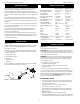
Palmgren Operating Manual & Parts List 9681109 & 9681108 DESCRIPTION SPECIFICATIONS Palmgren Model 9681109 6” x 10” Belt Disc Sander with stand and Model 9681108 6” x 14” Belt Disc Sander with cabinet are constructed of rugged cast iron and heavy gauge steel providing stability and vibration-free operation. The belt disc sanders are used to sand, deburr, bevel and grind large workpieces of wood, plastic and metal.
Palmgren Operating Manual & Parts List 9681109 & 9681108 • Handle workpiece correctly. Protect hands from possible injury. • Turn machine off if it jams. Belt jams when it digs to deeply into workpiece. (Motor force keeps it stuck in the work). • Support workpiece with miter gauge, belt platen or work table. • Maintain 1/16” maximum clearance between table and sanding belt or disc. CAUTION: Think safety! Safety is a combination of operator common sense and alertness at all times when tool is being used.
Palmgren Operating Manual & Parts List 9681109 & 9681108 6. Make sure that the clearance between disc table and abrasive disc does not exceed 1/16”. 7. Use a straight edge or square to check if the disc table is at right angle to the disc. ASSEMBLY (CONTINUED) ATTACH BELT TABLE Refer to Figure 2. Required parts and hardware: Belt table with trunnion, handle, and 8mm flat washer. 1. Position belt table on the belt housing so that the trunnion travels on the slide. 2.
Palmgren Operating Manual & Parts List 9681109 & 9681108 INSTALLATION (CONTINUED) Extension Cord Table Volts Total Length of Cord in Feet 120 25 50 100 150 Ampere Rating 240 50 100 150 300 More Not Than More Than Minimum Gage for Cord 0 6 18 16 16 14 6 10 18 16 14 12 10 12 16 16 14 12 12 16 14 12 Not Recommended • Do not remove or alter grounding prong in any manner. In the event of a malfunction or breakdown, grounding provides a path of least resistance for electrical shock.
Palmgren Operating Manual & Parts List 9681109 & 9681108 OPERATION (CONTINUED) HORIZONTAL BELT SANDING • For optimum performance, do not stall motor or reduce speed. Do not force the work into the abrasive. • Support workpiece with belt table when sanding with belt, with disc table when sanding with disc. • Never push a sharp corner of workpiece rapidly against belt or disc. Abrasive backing may tear. • Replace abrasives when they become loaded (glazed) or frayed.
Palmgren Operating Manual & Parts List 9681109 & 9681108 OPERATION (CONTINUED) REPLACING ABRASIVE DISC 1. 2. 3. 4. BELT TRACKING Belt should ride centered on drive and idler drums. The sander is shipped with the tracking mechanism properly adjusted. However, if adjustment is necessary: 1. Loosen knob on either side of belt housing. 2. Turn the unit on. 3. Insert a 1/8“ or 5/32“ hex wrench into the hole on adjusting nut on either side. 4.
Palmgren Operating Manual & Parts List 9681109 & 9681108 ELECTRICAL DIAGRAMS 9681109 Single Phase 115 V Figure 9 - 9681109 single phase 115 V electrical diagram. 9681109 Single Phase 230 V Figure 10 - 9681109 single phase 230 V electrical diagram.
Palmgren Operating Manual & Parts List 9681109 & 9681108 ELECTRICAL DIAGRAMS (CONTINUED) 9681108 Single Phase 115 V Figure 11 - 9681108 single phase 115V electrical diagram. 9681108 Single Phase 230 V Figure 12 - 9681108 single phase 230V electrical diagram.
Palmgren Operating Manual & Parts List 9681109 & 9681108 TROUBLESHOOTING SYMPTOM POSSIBLE CAUSE(S) CORRECTIVE ACTION 1. Low voltage 1. Check power line for proper voltage 2. Open circuit in motor or loose connections 2. Inspect all lead connections on motor for loose or open connection 1. Short circuit in line cord or plug 1. Insect line cord or plug for damaged insulation and shorted wires 2. Short circuit in motor or loose connections 2.
Palmgren Operating Manual & Parts List 9681109 & 9681108 NOTES 11
9681109 & 9681108 Figure 13 – Repair Parts Illustration for 9681109 Belt Palmgren Operating Manual & Parts List 12
Universal Handle M6*1.0P*20L Flat Washer 1/4"*25*2t Belt Table Support - Left Flat Washer 8.5*20*1.5t Cap Screw M8*1.25P*12L Cap Screw M5*0.8P*12L Spring Washer M5 Trunnion Trunnion Plate Belt Table Support - Right Belt Table Cap Screw 1/4"-20UNC*3/8"L Lock Handle Roll Pin 3*20L Flat Washer 12*23*2t Disc Spring Micro-Adjusting Seat Spring Adjusting Knob Flat Washer 3/8"*19*1t Screw Shaft of Support Bracket Nylon Nut 1/4"-20UNC Spring Eccentric Handle Cap Screw 1/4"-20UNC*1 1/4"L Nylon Nut M6*1.
9681109 & 9681108 Figure 14 – Repair Parts Illustration for 9681109 Disc Palmgren Operating Manual & Parts List 14
Key 5*5*70L Motor Hex. Screw M8*1.25P*20L Flat Washer 8.5*20*1.5t Strain Relief PG 13.5 Key 5*5*25L Spring Washer M8 Flat Washer 8.5*16*1.5t Flange 10" Disc Set Screw M8*1.25P*6L Clamp Block Cap Screw M6*1.0P*14L 10" Sanding Disc TJ32#80 End Cover Round Head Hex Screw M8*1.25P*45L Front Motor Guard Rear Motor Guard Cap Screw M6*1.0P*12L Flat Washer 6*12*1t Flat Washer 5.1*12*1t Round Head Screw M5*0.8P*10L Disc Guard Lock Knob M5*0.
Palmgren Operating Manual & Parts List 9681109 & 9681108 4203-B2 Figure 15 – Replacement Parts Illustration for 9681109 Base REPLACEMENT PARTS LIST FOR 9681109 BASE Ref. No. Description Part Number 1 2 3 4 5 6 7 8 9 10 11 12 13 14 Switch Round Head Screw M5*0.8P*10L Flat Washer 5.
Palmgren Operating Manual & Parts List 9681109 & 9681108 4203-B3 Figure 16 – Replacement Parts Illustration for 9681109 Stand REPLACEMENT PARTS LIST FOR 9681109 STAND Ref. No. Description Part Number 1 2 3 4 5 6 7 8 9 10 11 Stand Leg Stand Top - Long Long Rail Stand Top - Short Short Rail Carriage Bolt 5/16"-18UNC*1/2"L(7.9*1.7) Luck Nut w/Flange 5/16"-18UNC Hex. Nut M8*1.25P Leveling Pad Flat Washer 8.5*20*1.5t Hex. Screw M8*1.
9681109 & 9681108 Figure 17 – Repair Parts Illustration for 9681108 Belt Palmgren Operating Manual & Parts List 18
Universal Handle M6*1.0P*20L Flat Washer 1/4"*25*2t Belt Table Support - Left Flat Washer 8.5*20*1.5t Cap Screw M8*1.25P*12L Cap Screw M5*0.8P*12L Spring Washer M5 Trunnion Trunnion Plate Belt Table Support - Right Belt Table Cap Screw 1/4"-20UNC*3/8"L Lock Handle Roll Pin 3*20L Flat Washer 12*23*2t Disc Spring Micro-Adjusting Seat Spring Adjusting Knob Flat Washer 3/8"*19*1t Screw Shaft of Support Bracket Nylon Nut 1/4"-20UNC Spring Eccentric Handle Cap Screw 1/4"-20UNC*1 1/4"L Nylon Nut M6*1.
9681109 & 9681108 Figure 18 – Repair Parts Illustration for 9681108 Disc Palmgren Operating Manual & Parts List 20
Key 5*5*70L Motor Hex. Screw M8*1.25P*20L Flat Washer 8.5*20*1.5t Strain Relief PG 13.5 Key 5*5*25L Spring Washer M8 Flat Washer 8.5*16*1.5t Flange 14" Disc Set Screw M8*1.25P*6L Clamp Block Cap Screw M6*1.0P*14L 14" Sanding Disc TJ-32#80 End Cover Round Head Hex Screw M8*1.25P*45L Front Motor Guard Rear Motor Guard Cap Screw M6*1.0P*12L Flat Washer 6*12*1t Flat Washer 5.1*12*1t Round Head Screw M5*0.8P*10L Disc Guard Lock Knob M5*0.
9681109 & 9681108 Figure 19 – Repair Parts Illustration for 9681108 Base Palmgren Operating Manual & Parts List 22
Latch Door Door Pivot Spring E-Clip ETW-4 Switch Round Head Screw M5*0.8P*12L Flat Washer 5.1*12*1t Switch Plate Overload 125V/250V 18A Strain Relief Tooth Washer M5 Flat Washer 8.5*20*1.5t 1 2 3 4 5 6 7 8 9 10 11 12 13 (Δ) Not shown. (N/A) Not available as repair part. (*) Standard hardware item, available locally. Description Ref. No. 42041004 42041101 35022022 35022028 * 42011601 * * 42031024 42041601 51101007 * * Part No. 1 1 1 1 1 1 8 2 1 1 3 4 4 Qty. 14 15 16 17 18 19 20 21 22 23 24 25 26 Ref.
PALMGREN WARRANTY C.H. Hanson / Palmgren warrants their products to be free of defects in material or workmanship. This warranty does not cover defects due directly or indirectly to misuse, abuse, normal wear and tear, failure to properly maintain the product, heated, ground or otherwise altered, or used for a purpose other than that for which is was intended. The warranty does not cover expendable and/or wear part (i.e.