SUNLITE® Technical Guide Multiwall Polycarbonate Sheet
Content 1 2 Introduction 1 Product Range 1 Standard dimensions 1 Colors 2 Typical physical properties 2 Flammability 2 Chemical resistance, compatible sealants and adhesives 3 Arching radius 3 Wind and snow load calculation 4 Spacing and load calculations 4 Positioning of clamping profiles and fastener location 13 Preparation for glazing 14 Preparations prior to installation 15 Glazing profiles and fastening screws 15 Handling and storage 16 Cutting 16 Drilling 17 Sealin
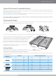
SUNLITE® Technical Guide Introduction This manual provides basic guidelines for selecting, handling and installing SUNLITE sheets. Due to their hollow core, preliminary preparation and additional care are required before the actual installation. Please note these guidelines before starting and follow them carefully. Product Range Product Description Application SUNLITE® Flat multiwall polycarbonate sheet with UV protective layer on one side. Suitable for both exterior and indoor applications.
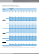
Colors* Standard Colors Structure LT = Light Transmission ST = Solar Transmission Multi-Layered Clear Bronze White Opal White Solar Guard Solar Solar Green** Blue** Bronze/Opal Diffuser (Solar Control/Opal) Ice Control** Twin wall 4mm 82% 35% 30% 35% 30% 30% Twin wall 4.
SUNLITE® Technical Guide Chemical Resistance & Compatible Sealants SUNLITE has good resistance to many chemicals. Some chemicals may harm the SUNLITE sheets. Detailed information about these materials can be found at the Chemical Resistance of Palram Polycarbonate Products brochure. Please contact your Palram dealer when in doubt about any material or chemical.
Wind and Snow Load Calculation Local building codes and standards in most countries provide details for required design loads, which should be consulted before installation. The information below is provided for general reference.
SUNLITE® Technical Guide Maximum Recommended Distances Between Centers- Shorter Spans (width) Under different ratios and loads for four sides clamped / framed flat glazing. Structure Thickness mm 6 Twin Wall 8 10 8 Triple Wall 10 16 16 25 X-Lite 32 35 Distance between centers (shorter span) according to ratio a:b Wind/snow uniform loads Ratio 1:1 Ratio 1.5:1 Ratio > 1.
2. Two-Sided Clamped Glazing This is a simpler glazing system to install, requiring no mid-sheet fastening, using long glazing sheets, and held in place by two glazing profiles on both longitudinal edges. It is not as strong, and permitted width is limited (the width direction of a multi-wall sheet is more vulnerable to loads, span-wise, especially the thinner, square ribbed 6 , 8 and 10 mm sheets).
SUNLITE® Technical Guide Maximum Recommended Spans between Arched Supports According to radius of curve and load for two sides clamped glazing. Structure Thickness mm 6 Twin Wall 8 10 8 Triple Wall 10 16 16 X-Lite 25 32 35 Sheet curvature radius Recommended (center-to-center) Distance between Supporting arches according to wind/Snow loads below 50 Kg/m² 10 psf 80 Kg/m² 16 psf 100 Kg/m² 20 psf 120 Kg/m² 24.
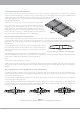
4. “Roofing & Cladding” Installation Method This is a simpler, more practical method, resembling the one used for single-wall, corrugated plastic (or metal) sheets. It employs longer strips, with wider dimension. Length is as long as possible without excess deformation by thermal expansion. SUNLITE sheets are laid on top of the purlins, with rib channels directed down the slope, perpendicular to the purlins.
SUNLITE® Technical Guide Combination of metal and plastic two-part connecting profile Offers added strength and rigidity. The lower part of the profile is made of metal- (mostly aluminum ), and the upper part is made of plastic (rigid PVC or polycarbonate), clipped on top of the metal profile, pressing on the edges of the two adjoining sheets.
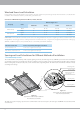
Mid-Sheet Fasteners (Not recommended for DIY Applications) 1. A wider sheet has to be fastened to the supporting structure by additional fastening along its width, as the connectors on both longitudinal sides are not enough to hold the sheet down, against the uplift force it has to withstand. 2. Fastening is usually done by screws, inserted along the supporting internal purlins, spaced about 500mm (20in.) apart. Figure 12 Schematic isometric view of partial installation with mid-sheet fasteners 3.
SUNLITE® Technical Guide 8. Screw buttons: Improved performance can be obtained by replacing the washers with special plastic screw buttons, fitted with a suitable rubber gasket, with or without a closing cap. They fit the thickness of each type of sheet (6, 8, 10, 16 mm, and possibly 25 mm), differing by sleeve length. Their advantage: the sleeve prevents excessive tightening and local squashing around the screw, and is softer on the sheet, reducing risk of tear or shear around the screw’s stem.
Maximum Recommended Distances between Support Purlins For Curved Roofing/Cladding, According to Curvature Radius and Load. Structure Thickness Sheet curvature radius mm 6 Twin Wall 8 10 8 Triple Wall 10 16 16 X-Lite 25 32 35 Recommended (center-to-center) Distance between Supporting arches according to wind/Snow loads below 50 Kg/m² 10 psf 80 Kg/m² 16 psf 100 Kg/m² 20 psf 120 Kg/m² 24.
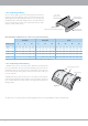
SUNLITE® Technical Guide Figure 15 Schematic description of standard curved roofing in a vault. SUNLITE glazing Supporting arched structure Supporting purlins Connecting profiles fastened to purlins General Notes for Structural Design 1. The recommended support spacing, as specified in the load/span tables, should not supersede the requirements of local structural and construction codes. The final values are to be dictated by actual conditions on site and engineering design. 2. The end spans, i.e.
Preparation for Glazing Determination of Rabbet Depth and Thermal Expansion Allowance These parameters depend on the SUNLITE sheet dimension, and relate to the four sides of the sheet (four-sides clamping system), or to the two edges parallel to the rib channels (two-sides clamping system). 1. Allowance for expansion - SUNLITE roughly expands 3mm for every meter (1/8 in. per 3 1/3 ft.) of length (or width) for a service temperature range of about 50°C (90°F), the practical working range in most cases.
SUNLITE® Technical Guide Preparations Prior to Installation 1. Ensure smaller thermal expansions by installing sheets - especially colored sheets - at ambient temperatures of 10-25 °C (50-77 °F). It is generally recommended to avoid installing sheets at colder or hotter temperatures. 2. Peel off the protective film at both open ends of the sheet (the width sides) to about 80-100 mm (3.5-4 in.) from the edges of the sheet, to enable taping of the aluminum sealing tape.
Handling and Storage 1. SUNLITE sheets should be transported and stored horizontally, on a flat, sturdy pallet whose dimensions are equal to or larger than the sheets themselves. The sheets must be secured and fastened to the pallet during transportation and handling on site. It is possible to stack the sheets with the longer sheets at the bottom and the shorter on top, leaving no unsupported overhang. 2. While moving a pallet with a forklift, always use forks as long as the sheets’ width.
SUNLITE® Technical Guide Drilling 1. Drilling can be carried out with drill bits intended for metal. When pre-drilling for a fastening screw, the hole’s diameter should be 2 mm larger than that of the screw used. As when cutting, always support the sheet in the vicinity of the place being drilled, and clean away the sawdust and shavings, both on and inside the sheet. 2. Special attention must be given to drill all the required holes perpendicular to the face of the sheet. 3.
General Recommendations for Working with SUNLITE® Sheets Cleaning 1. Keeping SUNLITE clean will yield the best long-term results. Self-cleaning by rain is usually sufficient. Local small areas may be washed using diluted mild household detergents. Make sure the detergent contains no abrasives or solvents. Pre-wash with warm water, then wash the stained area with a soft sponge or brush, preferably with hot water, until the stain disappears. Rinse with water and dry with a soft cloth. 2.
SUNLITE® Technical Guide 19 2
All marketing materials and any content therewith provided by Palram® are provided solely for the purpose of supporting and enhancing the marketing of Palram® products. These materials are protected by Palram’s intellectual property rights and may not be used for any other purpose or in connection with the sale of products of any other manufacturer. These materials may not be transferred to or used by any third party without prior permission of Palram. PALRAM EUROPE LTD.