Accu-Chek® Inform II BLOOD GLUCOSE MONITORING SYSTEM Operator’s Manual
Revision History Manual versions 1, 2, 3 and 3.x are for Accu-Chek Inform II meters with serial number versions UU13000000 to less than UU14000000. Manual versions 4, 5, 6 and 7.x are for Accu-Chek Inform II meters with serial number versions greater than or equal to UU14000000. Manual version Revision date Changes Version 1.0 2012-10 New document Version 2.0 2013-02 Upgrade to FW 03.04; Revise critically ill statement Version 3.0 2013-03 Update cleaning and disinfecting chapter Version 3.
ACCU-CHEK Inform II System ® Operator’s Manual Version 7.
© 2012-2021, Roche Diagnostics. All rights reserved. The contents of this document, including all graphics, are the property of Roche Diagnostics. No part of this document may be reproduced or transmitted in any form or by any means, electronic or mechanical, for any purpose, without the express written permission of Roche Diagnostics. Roche Diagnostics has made every reasonable effort to ensure that all the information contained in this manual is correct at the time of printing.
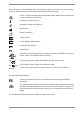
On the packaging, on the identification plate of the meter, the battery pack, the base unit, or the code key reader you may encounter the following symbols, shown here with their meaning: Caution, consult accompanying documents. Refer to safety-related notes in the instructions for use accompanying this product.
What is new in publication version 7.2? Updated information on WLAN regulatory registration. 08424705001 (04) 2021-06 USA • Accu-Chek Inform II Operator’s Manual Version 7.
What is new in publication version 7.2? 1 Introduction 1.1 Before you start......................................................................................................................................... CLIA Categorization ........................................................................................................................ Intended use ......................................................................................................................................
2 Powering Up and Entering an Operator ID 41 2.1 Powering up the meter........................................................................................................................... 41 Adjusting the display ...................................................................................................................... 42 Enabling/disabling wireless connectivity ................................................................................ 42 Closing startup ..........................
5 Review Results 5.1 Displaying test results from the memory ........................................................................................ Information stored in data records for test results.............................................................. List of results stored in the memory ......................................................................................... 6 Storing Test Strip, Control Solution, and Linearity Solution Information in the Meter 87 6.
9 Initial Startup 9.1 Connecting the base unit .................................................................................................................. 9.2 Installing or replacing the battery pack........................................................................................ Removing the battery pack........................................................................................................ Installing the battery pack ......................................................
11 Troubleshooting Errors and unusual behavior without error messages .................................................... Low power icons ........................................................................................................................... Pop-up messages ......................................................................................................................... Table of Information, Warning, and Error messages .......................................................
E Supplement for Enhanced Workflows E.1 Configurable workflows..................................................................................................................... Blood sample type selection ..................................................................................................... Isolation Room Workflow ........................................................................................................... Test procedure for patients in an isolation room ................
1 Introduction 1.1 Before you start CLIA Categorization This is a CLIA Waived system. A Certificate of CLIA Waiver (or higher) is required to perform the test. Information on obtaining CLIA certificates can be found at www.cms.hhs.gov/clia. Facilities performing testing must have a CLIA Certificate of Waiver. 42 USC 263a(c)(2). Laboratories with a certificate of waiver must follow the manufacturer’s instructions for performing the test. 42 CFR 493.15(e)(1).
Intended use The Accu-Chek Inform II test strips are for use with the Accu-Chek Inform II meter to quantitatively measure glucose (sugar) in venous whole blood, arterial whole blood, neonatal heel stick, or fresh capillary whole blood samples drawn from the fingertip as an aid in monitoring the effectiveness of glucose control. The system is not for use in diagnosis or screening of diabetes mellitus, nor for testing neonate cord blood samples.
Important information regarding use Read this operator's manual, as well as the package inserts for all relevant consumables, before using the system for the first test. You must configure the Accu-Chek Inform II system according to your needs before initial use. You can configure the system either directly on the meter or by using a suitable data management system. Refer to Chapter 9 “Initial setup on the meter” for on-meter configuration.
If you need help Information about using the system, the screen menus and performing a test can be found in this operator's manual. Error messages that appear on screen include information or instructions on how to correct the error. For all questions about the Accu-Chek Inform II system that are not answered in this manual, contact the Roche Customer Support Center at 1-800-440-3638 24 hours a day, 365 days a year.
What can the system do for you? The Accu-Chek Inform II system has the following features and properties: ■ Perform patient blood glucose tests and glucose control tests with control solution. ■ Automatically record all relevant data for the application, which includes: – Time and date of test – IDs for operator, patient, and samples – Information about control solutions, test strips, and linearity – Test results and comments – Patient sample type based on configuration.
1.2 Important safety instructions and additional information This section explains how safety-related messages and information related to the proper handling of the system are presented in the Accu-Chek Inform II manual. Please read these passages carefully. The safety alert symbol alone (without a signal word) promotes awareness to hazards which are generic or directs the reader to related safety information.
Important information regarding safety Operator qualification Only trained healthcare professionals may operate the Accu-Chek Inform II system. Operators must also have received comprehensive instruction in the operation, quality control, and care of the Accu-Chek Inform II system.
WARNING Avoidance of electrical shock, fire, and explosions ■ Only use Roche original accessories (cables, power supply units, battery packs, and spare parts). Thirdparty cables, power supply units, and battery packs can cause the battery pack to explode or the meter to become damaged. ■ Do not use loose power sockets or damaged power supply units, cables, plugs, or battery packs. ■ Do not short circuit the power supply unit, the base unit charging contacts, or the battery pack.
General care NOTICE To avoid damaging the system, use only solutions recommended to clean and disinfect the system. Using other solutions may result in incorrect operation and possible failure of the system. Accessory box NOTICE Meter Dispose of the meter in accordance with applicable laws and regulations. See “Disposal of the system” on page 20.
Shut down meter In standby mode (“Automatic power off”), energy continues to be drawn from the battery and it depletes within a day if not docked. Shutting down the meter shuts down wireless communication and all other functionalities. Date and time, however, are maintained. Powering up the meter will take slightly longer than from power-off (standby) mode.
Automatic shutdown In case of a Download Lockout (see page 161) or if the battery pack is critically low (see page 171), wireless communication and all other functionalities are shut down (although date and time are maintained). The meter can be configured to automatically shut down 30 minutes after power-off when it is NOT docked. This feature is enabled by default.
WARNING Possible hazards posed by the battery pack Damaged or swollen battery packs can overheat, catch fire, or leak. Immediately cease use of Accu-Chek Inform II meters with damaged or swollen battery packs and under no circumstances recharge them (do not place in the base unit). Overheating can cause the battery pack to catch fire or explode. ■ Never throw the battery pack or the meters onto a fire.
Observe the following general safety instructions for handling batteries: Disposal of used batteries Do not dispose of the battery pack with normal domestic waste. As a component of the Accu-Chek Inform II system, it must be deemed as potentially biohazardous. Treat it accordingly. See “Disposal of the system” on page 20. ■ When storing or disposing of the battery pack, use the manufacturer's original packaging.
Touchscreen NOTICE Use only your finger to touch the screen elements. Using a sharp-edged object (e.g., tip of a pen) can damage the touchscreen. ■ Do not use the system in direct sunlight. Direct sunlight may reduce the life expectancy and functionality of the display, as well as the integrity of test strips. ■ Electromagnetic compatibility (EMC) The Accu-Chek Inform II system complies with the emission and immunity requirements described in IEC 61326-2-6.
■ Reorient or relocate the receiving antenna. ■ Increase the separation between the equipment and receiver. ■ Connect the equipment into an outlet on a circuit different from that to which the receiver is connected. ■ Consult the dealer or an experienced radio/TV technician for help. This Class B digital apparatus complies with Canadian ICES-003.
Wireless connectivity Radiofrequency radiation exposure information If the meter is equipped with WLAN functionality: Wireless connectivity allows the meter to send data (test results, patient IDs, operator IDs, etc.) to the data management system without the need to return the meter to the base unit. This feature must be configured by the system administrator. Observe the guidelines of your facility for using wireless local area network connections.
Roche supports industry wireless standards and recommends using products that have Wi-Fi certification. This certification tests products to the 802.11 industry standards for basic connectivity, security, authentication, Quality of Service (QoS), interoperability and reliability.
Operation is subject to the following two conditions: (1) this device may not cause harmful interference, and (2) this device must accept any interference received, including interference that may cause undesired operation. NOTICE Changes or modifications made to this equipment not expressly approved by (Roche Diagnostics GmbH) may void the FCC authorization to operate this equipment.
Characteristics of strong passwords ■ Passwords must not contain the user’s account name or parts of the user’s full name that exceed two consecutive characters. ■ Passwords must be at least eight characters in length.
1.3 System components The Accu-Chek Inform II system includes the following components and accessories: A A Meter B Code key reader C Base Unit/Base Unit Light (power supply units not shown) D Base Unit Hub E Accessory box B The meter can be configured by two different methods: C D 1 Configuration via the Setup function on the meter (see Chapter 9) 2 Configuration via data management system Note: Not all options can be configured using the Setup function on the meter.
1.4 Overview of the meter 1 2 The meter has the following elements: 1 Test strip port Insert the test strip here. 2 Touchscreen (touch-sensitive display) This screen allows you to perform patient tests, perform controls tests, and review results. To select any of these functions, simply touch the button on the screen. 3 On/Off button Press this button to power the meter on or off.
8 8 Battery pack Powers the device. 9 Wireless LAN label If the meter supports wireless connectivity: This label displays registration numbers that are specific to the meter RF hardware. 10 Interface (For manufacturer’s use only.) 11 Battery pack connector socket Connect battery pack here. 9 10 11 8 08424705001 (04) 2021-06 USA • Accu-Chek Inform II Operator’s Manual Version 7.
1.5 Overview of the code key reader 14 13 Test strip vials include a code key.1 This code key is read by the code key reader and the data is sent to the meter. For additional information about the code key reader, see Chapter 6. The code key reader has the following elements: 12 Code key slot 13 LED (green) for displaying status 14 Infrared window for transmitting the code file to the meter 12 Introduction • 1 Do not replace code keys while the code key reader is still flashing.
1.6 Overview of the Accu-Chek Inform II Base Unit To provide flexibility in line with customer requirements, two versions of the base unit are available. 15 16 ■ The Accu-Chek Inform II Base Unit ■ The Accu-Chek Inform II Base Unit Light Both versions of the base unit can: ■ charge the meter battery pack. In addition, the Accu-Chek Inform II Base Unit supports: 17 ■ communication with a data management system.1 ■ communication with a computer.
18 19 20 21 22 Electrical connections are located on the back of the Accu-Chek Inform II Base Unit and the Base Unit Light. Illustration on the left shows the Accu-Chek Inform II Base Unit above, the Accu-Chek Inform II Base Unit Light below.
1.7 Overview of the Accu-Chek Inform II Base Unit Hub The Accu-Chek Inform II Base Unit Hub is able to connect up to 4 Accu-Chek Inform II Base Units Light (RJ25) and supports communication to a data management system via Ethernet (RJ45). The hub also provides power for the Accu-Chek Inform II Base Unit Light. When connected to a hub an Accu-Chek Inform II Base Unit Light does not require a separate power supply. The LED colors of the hub are the same as for the Accu-Chek Inform II Base Unit Light.
1.8 Overview of the accessory box The accessory box provides an area for storing and transporting consumables needed for performing point-ofcare blood glucose tests. 1.9 Reagents and consumables You need the following reagents to perform patient tests and glucose control tests: ■ Accu-Chek Inform II Test Strips ■ Accu-Chek Inform II Control Solutions: Available for purchase separately, consists of two 2.5 mL bottles.
1.10 Instructions for initial setup The meter must be configured prior to initial use. During this setup, the following parameters are configured: ■ Date and time format ■ Input mode for Patient ID ■ Input mode for Operator ID ■ Glucose controls: Type and schedule ■ Results screen for glucose control ■ Comments for entry after a test ■ Settings for data transfer You can perform these settings on a limited basis directly in the Setup Menu of the meter.
2 Powering Up and Entering an Operator ID 2.1 Powering up the meter 1 Press and release the On/Off button is now on. 2 The Power Up screen appears. 3 Check in the Power Up screen whether the date (lower left) and time (upper right) are displayed correctly. If necessary, refer to the instructions for updating these settings in Chapter 9. Power Up Performing self-checks... .
Adjusting the display Display Lighter Using the Display options, you can adjust the display contrast to the ambient light conditions. 12:48 pm Darker 1 In the Power Up screen, touch Contrast. The Display screen appears. 2 Touch darker. or 3 Touch to confirm the setting. to make the display lighter or After 30 seconds without any activity (e.g., without a screen touch) the meter automatically dims the display backlight to conserve energy (“Low Power Mode”).
Power Up If wireless connectivity is activated, the (RF OFF) icon is displayed as a button in the Power Up screen. 12:48 pm ■ To temporarily disable the wireless network connection, touch (RF OFF) in the Power Up screen. The icon then changes to (RF ON). ■ To temporarily enable the wireless network connection, touch (RF ON) in the Power Up screen. The icon then changes to (RF OFF). The RF ON/RF OFF button always displays the option you currently have.
Closing startup 2.2 Once you have completed all the necessary changes, ■ touch to proceed to the screen used to enter the operator ID, or ■ wait 5 seconds and the meter automatically proceeds to the screen used to enter the operator ID. Entering the operator ID How and when an operator ID is entered and if a password is required, depends on the configuration of the system. It is also, for example, possible to require the operator ID only when starting control tests.
Entering an operator ID with barcode scanner Operator ID When the screen for entering the operator ID is displayed: 12:48 pm 1 2 3 4 5 6 7 8 9 0 A-O 03/17/20 1 Press and release the barcode scanner button . The button now appears with a black background (during the scan). 2 Hold the meter so that the window of the barcode scanner is approx. 4-8 inches above the barcode you wish to read.
Entering the operator ID manually Operator ID 12:48 pm When the screen for entering the operator ID is displayed: Operator ID 12:48 pm MARIA Operator ID 12:48 pm MARIA S. 1 2 3 A B C D E P Q R S T 4 5 6 F G H I J U V W X Y 7 8 9 K L M N O Z . - 0 A-O 123 P-Z 123 A-O 03/17/20 03/17/20 03/17/20 1 Touch the letters or numbers to enter the ID.
3 Patient Glucose Testing 3.1 Information regarding blood glucose testing Patient Glucose Testing • 3 Before performing a blood glucose test, observe the following safety precautions: ■ Observe the applicable regulations and directives for hygiene and safety when collecting blood samples. ■ Observe the applicable regulations and directives for disposing of potentially infectious samples and materials.
Preparing to test For more detailed information regarding the Accu-Chek Inform II test strip, refer to the package insert for instructions for use, performance characteristics, and limitations of the system. The following requirements must be met before you can perform a test: Power Up 12:48 pm QC Due: Immediately ■ The Accu-Chek Inform II test strips are available.
If a glucose control test is shown as required, patient glucose testing cannot be performed until the controls are run successfully. Depending on how your meter is configured (see page 140), QC Lockout occurs when ■ ■ ■ ■ ■ patient testing is attempted and controls have not been run in the time interval or frequency established by your facility. controls have been run but the control values were not in range. new software has been installed.
3.2 Performing a patient glucose test Overview of test procedure A patient glucose test comprises the following steps: ■ Enter the patient ID. This can be done either manually or by using the barcode scanner. ■ Confirm that the test strip lot matches the test strips in use (if configured). ■ Perform the test. ■ Optionally a test may be categorized as an Observed Test Sequence (see page 241). 08424705001 (04) 2021-06 USA • Accu-Chek Inform II Operator’s Manual Version 7.
Entering or selecting the patient ID Main Menu 12:48 pm Patient Test Control Test Review Results Patient ID 12:48 pm 123456789 Patient ID 12:48 pm 123456789 1 2 3 A 4 5 6 F 7 8 9 K 0 A-O 03/17/20 Patient Confirmation B C D E L M N O P-Z 123 Patient ID: 123456789 Name: G H Miller I J Mary-Jane DOB: 12/03/56 Is this correct? 03/17/20 1 From the Main Menu screen touch Patient Test. 2 Enter or select the Patient ID as described on the following pages.
You now have three different options, depending on setup, for assigning the subsequent test to a patient. The patient ID function can be configured by your system administrator to: Enter any combination of up to 20 alphanumeric characters, with specified minimum and maximum lengths. Alphanumeric characters are any combination of A - Z and 0 - 9, additionally “.” (period), or “-” (hyphen) may be used. ■ ■ ■ Enter patient ID via barcode scanner.1 Select a patient from a list.
Entering the patient ID manually Patient ID 12:48 pm Use the displayed keypad to enter the patient ID. You can select characters in the same manner as when entering an operator ID. 1 Touch the letters or numbers to enter the ID. 2 Use the following buttons to toggle between ranges of characters: A B C D E – A-O for letters A-O F G H I J – P-Z for letters P-Z K L M N O – 123 for numbers 0-9 123 Touch to backspace and delete a character entered incorrectly.
Selecting the patient ID from a list Patient ID Keyboard Name: James Doe ID: 2222222222 Name: Jane Doe ID: 3333333333 Name: Jenny Doe ID: 4444444444 Name: John Doe ID: 123456789 12:48 pm Choose the patient ID from a list1, if a list has been downloaded to the meter (from the data management system). 1 Touch or to scroll up or down in the list. If one of the buttons is hidden, you have reached the top or bottom of the list.
Entering a patient ID with barcode scanner Patient ID 12:48 pm A B C ID D Patient E F G H I K L M N 123 P-Z 03/17/20 When the screen for entering the patient ID is displayed: 12:48 pm Keyboard J Name: James Doe ID:O2222222222 Name: Jane Doe ID: 3333333333 Name: Jenny Doe ID: 4444444444 Name: John Doe ID: 123456789 03/17/20 1 Press and release . The button now appears with a black background (during the scan). 2 Hold the meter so that the window of the barcode scanner is approx.
Confirming or selecting the test strip lot Patient Test Patient 123456789 12:48 pm Use Strip Lot 123456? 03/17/20 Strip Lots 12:48 pm 545794 344789 545777 344654 Once you have entered and confirmed the patient ID, you are asked to choose the lot number for the test strips. Compare the number displayed by the meter to the number on the label of the test strip vial. 1 Select the lot number as follows: ■ To read the lot number from the test strip vial via barcode scanner, press and release .
If the meter is configured to use the “Isolation Room Workflow” (see Appendix A.1) the strip lot will be confirmed before a patient ID is entered or selected. Patient Test 12:48 pm Strip Lots 12:48 pm Patient ID 12:48 pm 123456789 Use Strip Lot 123456? 545794 1 2 3 344789 4 5 6 545777 7 8 9 0 A-O 344654 03/17/20 03/17/20 03/17/20 The meter can be configured so that manual confirmation is not necessary. In this setup, only the lot number is displayed.
Patient identification information Patient Test Patient 123456789 DOB: 12/05/70 Strip Lot 545794 All available patient ID information for the selected patient is displayed on the Patient Test screen. Additional patient identifiers such as name and date of birth help verify patient identity. When performing a test, the operator can easily check whether the gender and age of the patient match the patient details shown on the screen.
Inserting test strips Patient Test Patient 123456789 DOB: 12/05/70 Strip Lot 545794 After confirming the test strip lot, a flashing green arrow appears on screen and prompts you to insert the test strip. 12:48 pm 03/17/20 Patient Test Patient 123456789 DOB: 12/05/70 Strip Lot 545794 12:48 pm 1 Remove the test strip from the test strip vial and close the vial with the cap. 2 Hold the test strip so the lettering “ACCU-CHEK” is facing upward.
Obtaining a blood sample Prepare the selected blood collection site and obtain blood from the patient per facility policy. Recommendations for the collection of capillary blood If no facility policy exists for obtaining capillary blood, the patient's hands (or heel in the case of small children) should be washed with warm water and soap, and then dried thoroughly.
Applying a blood sample Patient Test Patient 123456789 DOB: 12/05/70 Strip Lot 545794 Once the meter has checked the test strip, the hourglass icon disappears and you are prompted to apply a blood sample. 12:48 pm 03/17/20 1 Wait until the flashing drop appears in the display before applying the blood. The meter beeps. 2 Apply the drop of blood to the front edge (yellow dosing area) of the test strip. Blood is pulled into the test strip by capillary action.
Results screen Patient Test Patient 123456789 DOB: 12/05/70 Strip Lot 545794 The hourglass icon indicates the test is running. When the test is completed and the result is ready, the meter beeps again.
Patient Test 12:48 pm Patient 123456789 Date 03/17/20 12:48 pm 34 mg/dL Out of Crit.
The following messages1 may appear in instead of a numeric test result: ■ CR LO (below the Critical Range threshold, but within the Reportable Range) ■ CR HI (above the Critical Range threshold, but within the Reportable Range) ■ RR LO (below the Reportable Range threshold, but within the System Measurement Range) ■ RR HI (above the Reportable Range threshold, but within the System Measurement Range) ■ LO (below the System Measurement Range) ■ HI (above the System Measurement Range) For test
If comments are not set as required and you do not wish to add a comment to the test result, touch to return to the Main Menu. Test results are saved automatically if the meter is powered off or if it powers itself off after 10 minutes of inactivity/no screen touches (see “Automatic power-off” on page 21). Remove the test strip and dispose of it in accordance with applicable regulations and directives for disposal of potentially infectious samples and materials.
Patient Test 12:48 pm Patient 123456789 Date 03/17/20 12:48 pm 220 Add Comments Doctor Notified mg/dL Will Repeat Test Out of Normal Range 03/17/20 12:48 pm New Strip Lot RN Notified 03/17/20 Patient Test 12:48 pm Patient 123456789 Date 03/17/20 12:48 pm 220 mg/dL Out of Normal Range New Strip Lot Doctor Notified Will Repeat Test 03/17/20 To add comments: 1 In the Patient Test screen, touch .
Add barcode content to a result Patient ID A F K Barcode Confirmation C D E M N O ~Jane Doe%$X1234567 +5715486266Z?01-09G H I J 1979 L Patient ID P-Z 12:48 pm 123 A 03/17/20 F K Barcode Confirmation B C Jane Doe G H X1234567 5715486266Z 01-09-1979 L M P-Z 123 ■ Barcode content will not be added to the result ■ Barcode content will be added to the result ■ Barcode content will be displayed for confirmation after scanning and then added to the result If the meter is set to the las
Additional Patient Test 12:48 pm Patient Test Patient 123456789 Date 03/17/20 12:48 pm 150 It is possible to enable a patient test series (e.g. for plausibility checks). If this function is enabled (only possible via DMS), a pop-up dialog allows the operator to perform another test for the same patient immediately after the first test result is displayed. This function is also available for OTS and OTE workflows.
4 Glucose Control Testing 4.1 Information regarding glucose control tests Observe the applicable regulations and directives of the responsible regulatory agencies when performing glucose control tests. Accurately testing known levels of glucose ensures that the system and your technique used in testing give accurate results on patient tests. Glucose control solutions have defined (known) values.
Glucose control testing intervals Power Up 12:48 pm QC Due: Immediately Intervals between running glucose control tests are determined by your facility. These intervals are entered when the system is configured. At the end of the specified interval (or after a specific event such as starting to test with a new test strip lot), a warning is displayed when the meter is powered on and when the Glucose Test function is selected.
The following information is stored for every glucose control test using control solution: ■ Glucose control test result ■ Lot number of the control solution ■ Operator ID (if configured) ■ Level of control solution (L1 or L2) ■ Lot number of the test strips ■ Time and date of test ■ Comments (if applicable) ■ Out of range measurements Glucose Control Testing • 4 Information stored during glucose control testing 08424705001 (04) 2021-06 USA • Accu-Chek Inform II Operator’s Manual Versi
Control solutions Preparing to run a glucose control test For blood glucose test strips, control solutions have two levels: ■ Level 1 (L1): Lo (low values in test results) ■ Level 2 (L2): Hi (high values in test results) Aside from special preparations (see the following section), a glucose control test is run in the same manner as a patient test: ■ At least one code file for test strips must be stored in the meter and match the lot number of the test strips used (see Chapter 6).
4.2 Performing glucose control tests Overview of test procedure A glucose control test using control solution comprises the following steps: ■ Select the desired level of control solution for the test. ■ Check the lot number of the control solution. ■ Check the lot number of the test strips. ■ Perform the test with the control solution.
Starting a glucose control test Main Menu After preparing the meter as described, you can proceed to the steps directly related to control testing: Control Test 12:48 pm 12:48 pm Patient Test Level 1 (Lo) Control Test Level 2 (Hi) Required Review Results 03/17/20 03/17/20 1 From the Main Menu screen touch Control Test. In the Control Test screen, the levels available for the control solution are displayed.
Confirming or selecting the lot number for control solutions Control Test Control L2 (Hi) 12:48 pm Use Control Lot 123456? 03/17/20 Control Lot 12:48 pm 1 2 3 4 5 6 7 8 9 0 1 Select the lot number as follows: ■ To read the lot number from the control solution bottle via barcode scanner, press and release . Follow the instructions for scanning IDs (see page 45). ■ If you want to use the preselected number displayed by the meter, touch to confirm.
Confirming or selecting the test strip lot Once you have entered and confirmed the lot number of the control solution, you are asked to choose the lot number for the test strips. Compare the number displayed by the meter to the number on the label of the test strip vial. Control Test 12:48 pm Control L2 (Hi) 123456 1 Select the lot number as follows: ■ To read the lot number from the test strip vial via barcode scanner, press and release . Follow the instructions for scanning IDs.
Inserting test strips After confirming the test strip lot, a flashing green arrow appears on screen and prompts you to insert the test strip. Control Test 12:48 pm Control L2 (Hi) 123456 Strip Lot 545794 03/17/20 Control Test 12:48 pm Control L2 (Hi) 123456 Strip Lot 545794 1 Remove the test strip from the test strip vial and close the vial with the cap. 2 Hold the test strip so the lettering “ACCU-CHEK” is facing upward.
Applying the control solution Once the meter has checked the test strip, the hourglass icon disappears and you are prompted to apply control solution. Control Test 12:48 pm Control L2 (Hi) 123456 Strip Lot 545794 03/17/20 When applying the control solution, position the meter so that the test strip port is always higher or on the same level as the control solution. This prevents any excess solution from flowing down the strip and entering the meter.
Results screen The hourglass icon indicates the test is running. When the test is completed and the result is ready, the meter beeps again.
You can add comments to a control test result (as with blood glucose tests) (see page 65). For control tests, comments are only required if the result is outside the specified range (whether this is displayed as a value or as FAIL). If the result is within the specified range (displayed as a value or as PASS), comments are optional. If you do not wish to add a comment to the test result, touch to continue to the next level of the control test, if necessary, or to return to the Main Menu.
Performing a STAT test Patient Test Menu 12:48 pm QC Lockout Glucose Test Warning! Glucose control is due. Required Controls must be run in order to proceed. 9 STAT test(s) available. Run QC 03/17/20 Run STAT The meter can be configured to allow a STAT patient glucose test to be run even if the meter is in QC Lockout or Download Lockout. This option is to be used in situations with critical patients. The system administrator can allow control tests to be delayed one to nine times.
This page intentionally left blank. 08424705001 (04) 2021-06 USA • Accu-Chek Inform II Operator’s Manual Version 7.
5 Review Results 5.1 Displaying test results from the memory Information stored in data records for test results When you retrieve the data record for stored test results, the following information is displayed.
List of results stored in the memory Main Menu 12:48 pm Patient Test Control Test Review Results To display the results from the memory as a list: Glucose Results 12:48 pm All -- 01/17/20 -- mg/dL Time Rslt ID 7:15 pm 74 123456789ABC 5:32 pm 229 123456789ABC 2:25 pm 290 QC L2 12:15 pm 79 56789ABC1234 11:46 am 65 QC L1 10:01 am 74 Linearity L3 Patient 03/17/20 03/17/20 1 QC Glucose Results 12:48 pm All -- 01/17/20 -- mg/dL Time Rslt ID 7:15 pm 74 123456789ABC 5:32 pm 229 123456789ABC 2:25 pm FAIL
Glucose Results 12:48 pm All -- 01/17/20 -- mg/dL Time Rslt ID 7:15 pm 74 123456789ABC 5:32 pm 229 123456789ABC 2:25 pm FAIL QC L2 12:15 pm 79 56789ABC1234 11:46 am PASS QC L1 10:01 am 74 Linearity L3 Patient 03/17/20 QC 12:48 pm Patient Result ID: 123456789ABCDEFG Name: Joe M.
Glucose Results 12:48 pm All -- 01/17/20 -- mg/dL Time Rslt ID 7:15 pm 74 123456789ABC 5:32 pm 229 123456789ABC 2:25 pm FAIL QC L2 12:15 pm 79 56789ABC1234 11:46 am PASS QC L1 10:01 am 74 Linearity L3 Patient 03/17/20 QC 5 Touch QC, if you wish to display a list of glucose control tests. If the meter is configured to show PASS/FAIL instead of a numerical QC result, you can use the list to check whether a meter lockout is due to a failed or overdue control test.
6 Storing Test Strip, Control Solution, and Linearity Solution Information in the Meter 6.1 Storing information about test strips This procedure also allows the code key information to be stored centrally in the data management system, from where it can be sent to all the meters used in your facility. Make sure with each test that the code stored (and selected by you) matches the lot number of the test strips in use.
Transferring code key information to the meter Main Menu 12:48 pm Patient Test Control Test Review Results 03/17/20 The following description assumes that the meter is powered on and the Main Menu is displayed. Main Menu 2 12:48 pm Maintenance Beeper Proficiency Diagnostics Strip Lots Linearity Control Lots Linearity Lots Order Strips Admin. 03/17/20 Strip Lots Type Exp. Date * Strip 05/21/20 Strip 06/31/20 Strip 06/21/20 12:48 pm Lot Num.
5 Place the code key reader on a level surface such as a bench. Hold the meter 4-6 inches above the code key reader so that a connection can be made between the two infrared windows. 6 Touch ■ The code file is ready for transmission as long as the LED on the code key reader is flashing, even if the code key is removed. to begin downloading data. – If you get an error message that the download was not successful, re-insert the same code key and try again.
Add Strip Lot Information about the expiration date and parameters for control solutions is subsequently displayed. 12:48 pm Strip Lot Confirmation 1 Do you want to use the suggested values for strip 545603? Use by: 12/10/20 L1(Lo): 43-74 mg/dL L2(Hi): 288-389 mg/dL Touch to store the data for this lot number in the meter without changes, or touch to modify the data for this lot number before storing it in the meter. If you accept the suggested values the following screen appears.
Editing test strip data Add Strip Lot As mentioned at the beginning of this chapter, you can edit several parameters for test strips, the expiration date and the value ranges for control solutions. 12:48 pm 1 Use the keypad to enter the desired expiration date (use two digits and leading zero, if necessary). It is not possible to enter a date beyond the expiration date stored in the key. 2 Touch to accept the modified date and continue to the value ranges.
The parameters for control solutions consist of four separate values. Strip Expiration 12:48 pm 05/30/20 Control L2 Min 261 12:48 pm mg/dL Control L2 Max 353 12:48 pm mg/dL 1 2 3 1 2 3 1 2 3 4 5 6 4 5 6 4 5 6 7 8 9 7 8 9 7 8 9 0 . 0 .
Control L2 Max Once you have finished updating the test strip information, you can use the next screen to select the lot number you are currently editing as the current lot number. 12:48 pm 353 mg/dL 4 2 3 The current lot number is provided automatically for use with subsequent tests.
6.2 Storing control solution information Glucose control solution lot information can be entered before testing, if lot editing has been allowed at the meter level in the setup, and appears in a list for operators to refer to. Use the following procedure to add glucose control lot numbers to the Control Lot list.
12:48 pm Control Lot 12:48 pm 123456 Control Expiration 12:48 pm 05/30/20 Level 1 (Lo) 1 2 3 1 2 3 Level 2 (Hi) 4 5 6 4 5 6 7 8 9 7 8 9 0 03/17/20 0 03/17/20 03/17/20 4 Select the level (L1/Lo or L2/Hi). 5 Use the keypad to enter the lot number. Touch to confirm the entered lot number, or press and release to read the lot number from the control solution bottle via barcode scanner. Follow the instructions for scanning IDs (see page 45).
Control Expiration 12:48 pm 05/30/20 1 4 2 3 5 6 Make 'Current' Do you want to make Control lot 134526 the 'current' lot for Level 1 (Lo)? Once you have finished updating the control solution information, you can use the next screen to select the lot number you are currently editing as the current lot number. The current lot number is provided automatically for use with subsequent tests.
Main Menu 12:48 pm Patient Test Control Test Review Results 03/17/20 You can select any stored lot number as the current lot number. Main Menu 2 12:48 pm Maintenance Beeper Proficiency Diagnostics Strip Lots Linearity Control Lots Linearity Lots Order Strips Admin. 03/17/20 Control Lots Type Exp. Date * QC L2 05/21/20 QC L1 06/31/20 QC L2 05/21/20 12:48 pm Lot Num. 777678 777732 777723 Add 03/17/20 1 Touch in the Main Menu to open the Main Menu 2 screen.
Control Lots Type Exp. Date * QC L2 05/21/20 QC L1 06/31/20 QC L2 05/21/20 12:48 pm Lot Num. 777678 777732 777723 Control Lot Details Control Lot: 777732 Control Level: 1 Use by 06/31/20 12:48 pm Control Lot Details Control Lot: 777732 Control Level: 1 Use by 06/31/20 Current 12:48 pm Make Current Add Edit 03/17/20 03/17/20 Delete Edit Delete 03/17/20 3 Touch the lot number you wish to select as the current lot number. This opens the related detail view.
6.3 Storing linearity test information Observe the applicable regulations and directives of the responsible regulatory agencies when performing linearity tests. Main Menu 12:48 pm Patient Test Control Test Review Results 03/17/20 The following description assumes that the meter is powered on and the Main Menu is displayed. Main Menu 2 12:48 pm Maintenance Beeper Proficiency Diagnostics Strip Lots Linearity Control Lots Linearity Lots Order Strips Admin. Linearity Lots Type Exp.
Linearity Lot Linearity Expiration 12:48 pm 777678 12:48 pm 03/31/20 1 2 3 1 2 3 4 5 6 4 5 6 7 8 9 7 8 9 0 A-O 0 03/17/20 Linearity Lots Type Exp. Date * Lin. 12/31/20 Lin. 05/15/21 03/17/20 12:48 pm Lot Num. 777732 777723 4 Use the keypad to enter the lot number. 5 Touch 6 Enter the expiration date (use two digits and leading zero, if necessary) and touch to confirm the expiration date you have entered. to confirm the entered lot number.
Main Menu 12:48 pm Patient Test Control Test Review Results 03/17/20 You can select any stored lot number as the current lot number. Main Menu 2 12:48 pm Maintenance Beeper Proficiency Diagnostics Strip Lots Linearity Control Lots Linearity Lots Order Strips Admin. 03/17/20 Linearity Lots Type Exp. Date * Lin. 06/21/20 Lin. 07/31/20 Lin. 06/21/20 12:48 pm Lot Num. 777678 777732 777723 Add 03/17/20 1 Touch in the Main Menu to open the Main Menu 2 screen.
Linearity Lots Type Exp. Date * Lin. 06/21/20 Lin. 07/31/20 Lin. 06/21/20 12:48 pm Lot Num. 777678 777732 777723 Linear. Lot Details Linearity Lot: 777732 Use by 12/31/20 12:48 pm Linear. Lot Details Linearity Lot: 777732 Use by 12/31/20 Current 12:48 pm Make Current Add Edit 03/17/20 03/17/20 Delete Edit Delete 03/17/20 3 Touch the lot number you wish to select as the current lot number. This opens the related detail view.
7 Linearity Testing 7.1 Information regarding linearity tests Observe the applicable regulations and directives of the responsible regulatory agencies when performing linearity tests. For information about sources for products required during linearity testing or for technical assistance, contact Roche Customer Support Center. Linearity tests can help you to check the function and accuracy of the entire system over the full range of specified values.
Linearity testing intervals The linearity of the system should be checked before it is used the first time for patient testing. The intervals for subsequent linearity tests are determined by the facility that operates the system. Linearity testing can also be run when you want to check the overall performance of the system.
Linearity test kit The linearity test kit contains glucose solutions in six levels (6 vials, 2.5 mL each). For additional information about the contents and handling of the kit, refer to the package insert. Preparing to run a linearity test Aside from special preparations (see the following section), a linearity test is run the same as a patient test.
7.2 Performing a linearity test Overview of test procedure Starting a linearity test Main Menu 12:48 pm Patient Test Control Test Review Results 03/17/20 A linearity test comprises the following steps: ■ Check the lot number of the linearity solutions. ■ Check the lot number of the test strips. ■ Perform the test with a minimum of three linearity solutions. The following description assumes that the meter is powered on and the Main Menu is displayed.
Confirming or selecting the lot number for linearity test kits Linearity Test 12:48 pm You are now prompted to confirm or enter the lot number of the linearity test kit. Compare the number displayed by the meter to the number on the label of the linearity test kit. 3 If you want to use the preselected number displayed by the meter, touch to confirm. To use a different number than the lot number displayed, touch to open the keypad and enter the number manually (see page 99).
Linearity Test Linearity 12345678 Strip Lot 545794 12:48 pm In the Linearity Test menu, the levels available for the linearity test are displayed. 5 L1 L2 L3 L4 L5 L6 03/17/20 Inserting test strips Touch L1 to start the subsequent test with this (first) level. After selecting the level, a flashing green arrow appears on screen and prompts you to insert the test strip.
Applying a linearity test sample Once the meter has checked the test strip, the hourglass icon disappears and you are prompted to apply linearity solution. Linearity Test 12:48 pm Linearity 12345678 L1 Strip Lot 545794 03/17/20 1 Wait until the flashing drop appears in the display before applying the solution. The meter beeps. 2 Apply a drop of the linearity solution to the front edge of the test strip. Do not apply the solution to the top of the strip.
Results screen Linearity Test 12:48 pm Linearity 12345678 L1 Strip Lot 545794 The hourglass icon indicates the test is running. When the test is completed and the result is ready, the meter beeps again. Linearity Test 12:48 pm Linearity 12345678 L1 Date 03/17/20 12:48 pm 45 03/17/20 03/17/20 mg/dL Linearity Test Linearity 12345678 Strip Lot 545794 12:48 pm L1 L2 L3 L4 L5 L6 03/17/20 You can add comments to a test result (as with blood glucose tests, see page 65).
8 Proficiency Testing 8.1 Information regarding proficiency tests Observe the applicable regulations and directives of the responsible regulatory agencies when performing proficiency tests. Blood glucose proficiency tests are run on samples whose values are unknown to the operator performing the test. These samples are provided by an outside source, and the results should be forwarded to the appropriate source after completing the test.
Information stored during proficiency testing The following information is stored for every proficiency test: ■ Test result ■ Sample ID ■ Lot number of the test strips ■ Time and date of test ■ Comments (if applicable) ■ Operator ID (if configured) For blood glucose proficiency tests, the sample ID (instead of patient ID) must be stored as identification. Sample IDs with up to 20 characters can be entered.
8.2 Performing a proficiency test Overview of test procedure Starting a proficiency test Main Menu A proficiency test comprises the following steps: ■ Enter a sample ID for the proficiency sample. ■ Check the lot number of the test strips. ■ Perform the actual test with the proficiency sample. The following description assumes that the meter is powered on and the Main Menu is displayed.
Entering the proficiency sample ID Sample ID 12:48 pm 1 2 3 4 5 6 7 8 9 0 A-O You will now be asked to enter the sample ID. 1 Use the keypad to manually enter the sample ID, or press and release to read the sample ID from the sample vial via barcode scanner (see page 45). Make sure in this case that the proficiency sample has a compatible barcode (see Appendix A). 2 Touch to confirm the selected or scanned sample ID.
Inserting test strips Proficiency Test Sample 123456789 Strip Lot 545794 After confirming the test strip lot, a flashing green arrow appears on screen and prompts you to insert the test strip. 12:48 pm 03/17/20 Proficiency Test Sample 123456789 Strip Lot 545794 12:48 pm 1 Remove the test strip from the test strip vial and close the vial with the cap. 2 Hold the test strip so the lettering “ACCU-CHEK” is facing upward.
Applying a proficiency sample Proficiency Test Sample 123456789 Strip Lot 545794 Once the meter has checked the test strip, the hourglass icon disappears and you are prompted to apply the proficiency sample. 12:48 pm 03/17/20 When applying the proficiency sample, position the meter so that the test strip port is always higher or on the same level as the sample. This prevents any excess sample from flowing down the strip and entering the meter.
Results screen The hourglass icon indicates the test is running. When the test is completed and the result is ready, the meter beeps again. Proficiency Test 12:48 pm Sample 123456789 Date 03/17/20 12:48 pm 150 03/17/20 12:48 pm Proficiency Test Sample 123456789 Date 03/17/20 12:48 pm 12:48 pm Proficiency Test Sample 123456789 Date 03/17/20 12:48 pm HI LO mg/dL 03/17/20 03/17/20 The result is displayed as a numerical value, unless it falls outside the system measurement range.
This page intentionally left blank. 08424705001 (04) 2021-06 USA • Accu-Chek Inform II Operator’s Manual Version 7.
9 Initial Startup 9.1 Connecting the base unit NOTICE To ensure continuous safe and reliable operation, use only the power supply unit provided for the Accu-Chek Inform II system (for ordering information see page 188). Accu-Chek Inform II Base Unit: Initial Startup • 9 Accu-Chek Inform II Base Unit Light: 08424705001 (04) 2021-06 USA • Accu-Chek Inform II Operator’s Manual Version 7.
1 Slide the base unit upward and remove it from the wall mount (if in use). 2 Connect the power supply to the power input jack. 3 If you want to connect the Accu-Chek Inform II Base Unit in a wired environment: Connect the Ethernet (RJ45) cable or the USB cable to the respective port. Use only the USB cable provided with the Accu-Chek Inform II system. 4 Slide the base unit back onto the wall mount (if in use).
9.2 Installing or replacing the battery pack When shipped, the battery pack is not installed in the Accu-Chek Inform II meter. Unused battery packs lose their charge over time and have to be recharged before they can be used. After installing a new battery pack, the meter should be charged for at least 8 hours (e.g., overnight) in the base unit before testing. Whenever the meter is in the base unit, the icon is displayed. This icon shows that power is available and the meter can charge, if necessary.
Removing the battery pack If a battery pack is already installed, make sure that the meter is shut down to prevent damage to the meter or potential data loss. 1 To shut down the meter, press the the On/Off button for about 5 seconds and release the On/Off button as soon as the Roche logo is displayed and the meter beeps. If you press the On/Off button for too long, a meter reset will be triggered after about 12 seconds (see section “Meter reset” on page 181.
3 Using a Torx screwdriver size T5, remove the three screws holding the battery compartment cover in place. 4 Remove the battery compartment cover from the meter. The battery pack now visible is connected to the meter by a plug. 5 Carefully lift the battery pack and remove the plug connector. Initial Startup • 9 Disposal of used batteries Do not dispose of the batteries with normal domestic waste.
Installing the battery pack 1 Loosen the screws on the battery compartment cover until they are protruding about 2/10 inch. 2 Hold the battery pack in your hand, with the wires and the plug pinched between your thumb and index finger. 3 Plug the connector plug into the socket. 4 Place the battery pack inside the battery compartment as shown above.
5 Close the battery compartment with the cover. Make sure that the plug connector wires do not get pinched between meter and cover. 6 Tighten all three screws until snug (do not overtighten). After inserting a new battery pack, the meter powers on automatically. Date ■ The Roche logo is displayed. If the meter does not power on automatically, the battery pack may be nearly empty. Place the meter in a base unit for a minimum of 15 minutes, then remove the meter and try to power it on.
9.3 Docking the meter Docked screen - battery status Docking the meter in the base unit allows you to charge the battery pack. The Docked screen displays a large battery icon showing the current charging status of the battery. This information enables you to choose the meter with the best battery status for the next test. Battery status is displayed as follows: Docked 12:48 pm Icon Description Battery is empty and device cannot be used. Software updates and WLAN disabled. Transferring...
Improved charging performance After 2 minutes in the base unit, the meter powers off and goes into standby mode. The screen goes blank and the charging process starts. Charging the battery pack in standby mode improves charging performance. When the screen is blank during the charging process, you can power on the meter at any time to check the battery charging status or that the meter is properly docked by touching the screen or pressing the On/Off button .
Docked screen - meter status When docked, the meter shows different messages according to the current meter status. The following displays appear on the meter when it is docked in an Accu-Chek Inform II Base Unit or an Accu-Chek Inform II Base Unit Light and communicating. The same displays appear whether the meter is transferring data via base unit or via wireless connection. Docked 12:48 pm Connecting... Docked Synchronizing Database...
Docked 12:48 pm This display is visible when no communication is taking place. 12:48 pm This display is visible when software updates are being transferred to the meter. Idle 03/17/20 Docked Updating Software... 03/17/20 If the meter transfers data wirelessly immediately after a test, this communication is not visible on the display. The display remains unchanged (usually in the Main Menu view after a test).
9.4 Initial setup on the meter There are two ways to customize the setup of the meter: directly on the meter (see the following menu overview) or via the data management system (see Appendix A). The two methods differ according to the range of options available. If the meter is configured by a system administrator using a data management system, the configuration options on the meter may be disabled to avoid conflicts in the settings. These options then appear grayed out on the display.
Menu overview The following tables contain a brief overview of the menu structure. The menus can be used to operate the meter fully and enter the most important basic settings.
Main Menu 2 Maintenance – Add Comment – Maintenance Result Proficiency – – – – – – Enter Sample ID Verify Test Strip Lot Insert Test Strip Apply Sample View Test Results Add Comments Strip Lots – – – – – – – View Lot List Add Lot Enter Expiration Date Set Control Ranges View Lot Details Make Lot Current Edit/Delete Lot Control Lots – – – – – – View Lot List Select Control Level Add Lot Enter Expiration Date Make Lot Current Edit/Delete Lot Order Strips – Trigger ordering of test strips Bee
Main Menu 2 Linearity Linearity Lots – – – – – – – Verify Linearity Lot Verify Strip Lot Select Linearity Level Insert Test Strip Apply Linearity Solution View Test Results Add Comments – – – – – View Lot List Add Lot Enter Expiration Date Make Lot Current Edit/Delete Lot Language – German, French, Spanish, Italian, Dutch, Swedish, English, Danish, Portuguese – Additional installable languages Date/Time – Enter Current Date – Enter Current Time Setup Menu Date/Time Options – Date/Time Editi
Admin Menu Service Menu1 Touch 1. Delete Patient Information – Delete all patient-related data (patient list and results) to confirm and save any changes to the settings. Only if activated via DMS 08424705001 (04) 2021-06 USA • Accu-Chek Inform II Operator’s Manual Version 7.
9.5 Opening the Setup Menu All settings described here are configured via the Setup Menu. To open the Setup Menu, proceed as follows: Main Menu 2 12:48 pm Admin Menu 12:48 pm Setup Menu 12:48 pm Maintenance Beeper Date / Time Date / Time Reagents Proficiency Diagnostics Setup Menu Test Display Test Ranges Strip Lots Linearity Language Selection QC Password Control Lots Linearity Lots Service Menu Operator ID Patient ID Order Strips Admin.
9.6 Date and time format Date/Time Options 12:48 pm Date/Time Editing Allowed Password Needed Not Allowed Time Format 12 hour (AM / PM) 24 hour Date Format mm/dd/yy dd.mm.yy Use this menu to select the date and time format for the display. You can also choose whether the operator is allowed to edit date and time (optionally with password required, see “Creating a setup password” on page 145).
9.7 Display options and optional tests Test Disp. Options 12:48 pm Display Strip Limitations Warning Result Units mg/dL mmol/L Enable Tests: Stat Linearity Proficiency Maintenance Use this menu to select the unit of measure for test results and enable or disable optional tests.
9.8 Options for test strips Reagent Options 12:48 pm Reagent Editing Allowed Password Needed Not Allowed Strip Lot Verification Display only Confirmation List selection Scan only This menu allows you to select options for handling lot numbers and specify whether the operator is allowed to add or delete reagent lots, edit the expiration date and limit values on the meter (see “Creating a setup password” on page 145).
Reagent Options 12:48 pm Control Lot Verification Display only Confirmation Lot entry Scan only Linearity Lot Verification Display only Confirmation Lot entry On the second settings screen, you can select options for handling lot numbers with glucose control and linearity tests. 1 Touch the desired option to enable it: ■ Control Lot Verification – Display only: The lot number is shown on screen but the operator cannot confirm it or select a different lot number.
9.9 Options for glucose control tests QC Frequency 12:48 pm Control Frequency Always OK Last QC OK Hours Strip Count Shift Time Of Day 1 ■ 12:48 pm – Hours: QC Lockout is activated after the specified time. When a glucose control test is run successfully, the counter is reset to “0”. 50 2 3 4 QC Strips 5 6 7 50 8 0 03/17/20 Control Frequency – Last QC OK: QC Lockout is activated only when the last glucose control test is out of range or a control test is not available (e.g.
– Shift: QC Lockout is activated per shift. – Time Of Day: QC Lockout is activated at the specified time of day. (Up to six times per day can be configured.) – Rotating QC: QC tests require alternating use of L1 and L2 controls, instead of requiring both controls when performing a QC test. 2 Touch to save the settings. If the Hours or Strip Count option is enabled, enter the desired number, or touch to exit this menu without saving any changes.
9.10 Value ranges (normal, critical, reportable) This menu allows you to set limit values for results as Normal, Critical, or Reportable. Results outside these limits will be flagged to alert you of this event. The Reportable Range allows the system administrator to set an institution defined range for reporting patient results.
9.11 Options for Operator ID Entry Operator ID Entry 12:48 pm Operator Entry None Prompt Scan only Prompt (numeric only) Operator Validation None Length List List with password This menu allows you to specify if and how operator login is performed. 1 ■ Operator Entry – None: The meter can be used without operator login. – Prompt or Prompt (numeric only): Operator login is required. The Operator ID can be entered manually via keypad or via barcode scanner. – Scan only: Operator login is required.
9.12 Patient ID options This menu allows you to specify the criteria for entering a patient ID. 12:48 pm Patient ID Options Patient Entry Prompt Prompt (numeric only) Scan only Prompt or List 1 ■ Touch the desired option to enable it: Patient Entry – Prompt or Prompt (numeric only): The Patient ID can be entered manually via keypad or via barcode scanner. – Scan only: Entry of ID via barcode scanner only.
9.13 Creating a setup password This screen allows you to create a password for all the settings described in this chapter as well as for editing date/time and lot information (if password protected). The setup password ensures that only authorized persons can make changes to the setup. Please note that password protection can only be reset or modified after entering the current password. Proper authentication is required to access the Setup Menu. Store your password in a safe place.
9.14 Setting the date and time This setting can be hidden or require entry of the setup password, based on configuration. Main Menu 12:48 pm Patient Test Control Test Review Results Main Menu 2 12:48 pm Date 12:48 pm 11/30/20 12:48 pm Maintenance Beeper Date / Time Proficiency Diagnostics Setup Menu Strip Lots Linearity Language Selection Control Lots Linearity Lots Service Menu Order Strips Admin.
9.15 Beeper options This setting can be used to set the volume of the beeper. Main Menu 12:48 pm Patient Test Control Test Review Results 12:48 pm Maintenance Beeper Proficiency Diagnostics Strip Lots Linearity Control Lots Linearity Lots Order Strips Admin. Beeper Setup Beeper Volume: 12:48 pm Low Medium High 03/17/20 03/17/20 1 Touch in the Main Menu to open the Main Menu 2 screen. 2 Touch Beeper to set the volume. 3 Touch the button with the desired volume.
08424705001 (04) 2021-06 USA • Accu-Chek Inform II Operator’s Manual Version 7.
10 Maintenance and Care 10.1 Conditions for storage and shipping All information given on maintenance and care of the “base unit” in this chapter applies to both the Accu-Chek Inform II Base Unit and the Accu-Chek Inform II Base Unit Light. General operating conditions Please observe the following points to ensure the reliable operation of your system over the long term: ■ Handle the meter and its system components with care. Avoid dropping it or banging it.
Shipping Observe the following safety information when shipping the meter and battery pack. Failure to do so may result in injury to persons or damage to the meter or battery pack. ■ If the meter has to be shipped or transported over long distances, always remove the battery pack from the meter. This eliminates the possibility of the battery pack overheating due to a short circuit. It also prevents deep discharge and other damage to the battery pack or meter. ■ Only ship undamaged battery packs.
Storage ■ Store the system and test strips in the same environment in which they are used. ■ Do not store the meter in direct sunlight or under extreme temperature conditions. ■ Observe the limits for temperature and humidity when storing and using the meter (see Chapter 12). 10.2 Cleaning/disinfecting the Accu-Chek Inform II system Cleaning and disinfecting the exterior surface of the meter is, at minimum, recommended daily for dedicated patient devices.
Guide to cleaning and disinfecting the Accu-Chek Inform II system Cleaning and disinfecting the meter Prior to cleaning and disinfecting a blood glucose testing equipment: 1 Follow the infection control procedures of your institution when handling blood glucose testing equipment 2 Wear gloves 3 The gloves worn during cleaning and disinfecting should be removed and hands washed thoroughly with soap and water before performing the next patient test ■ Clean the meter to remove visible soil and or
Acceptable cleaning/ disinfecting agents ■ To purchase approved disinfecting products, please refer to your facility’s guidelines, which may include instructions on direct purchase from the agent manufacturer or through an approved distributor. For additional information on product availability for purchase, refer to manufacturer’s website: http://www.cloroxprofessional.com for Clorox® Germicidal Wipes or http://www.pdipdi.com/ for Super Sani-Cloth® Germicidal Disposable Wipes.
What to clean/disinfect Technical assistance The following parts of the meter and system components may be cleaned and disinfected: ■ The area around the test strip port ■ The meter display (touchscreen) ■ The meter housing (entire meter surface) If you notice any of the following signs of deterioration after cleaning or disinfecting of your meter system, stop using the system component and contact Roche Customer Support Center at 1-800-440-3638 for assistance: ■ clouding of the touchscreen di
10.3 How to clean and disinfect the Accu-Chek Inform II system WARNING Avoid getting liquid into the test strip port! Failure to follow these instructions may damage the meter and stop it from working properly. ■ Do Not clean or disinfect the meter while performing a blood glucose or control test. ■ Do Not get any moisture in the test strip port. ■ Do Not spray anything onto the meter. ■ Do Not immerse the meter in liquid.
Cleaning the meter 1 Place the meter on a level surface prior to cleaning. 2 Power off the meter. Be certain that solutions contain acceptable active ingredients for cleaning the system. When using commercially available pre-moistened cleaning cloths, squeeze off excess cleaning solution or blot on a dry paper towel to remove any excess cleaning solution before cleaning the surface of the meter.
Disinfecting the meter NOTE: The meter should be cleaned prior to each disinfection step. Remember to keep the meter on a level surface prior to disinfecting and powered off. Be certain that solutions contain acceptable active ingredients for disinfecting the system. When using commercially available premoistened disinfecting cloths, squeeze off excess disinfecting solution or blot on a dry paper towel to remove any excess disinfecting solution before disinfecting the surface of the meter.
10.4 Logging maintenance activities Cleaning, disinfecting, and other maintenance activities can be logged in the meter. Make sure that all cleaning activities are complete and the system is thoroughly dry before powering on the meter. All logged maintenance comments can be reviewed later using the Review Results function of the meter (see page 83ff).
10.5 Diagnostics view Under Diagnostics you can find information about the system, such as software version, number of data records stored, and configuration details. Use this menu to display stored error messages and test the barcode scanner and the wireless status (if your meter is equipped with the WLAN option). The Diagnostics screens shown here are for illustration purposes only. Information shown on your meter may differ.
Diagnostics Log Details 12:48 pm Log Entry 1 Date 03/15/20 10:39 am Event Type: Error Message Code: E-NCB Battery Critically Low 12:48 pm Log Serial No: 14300740 S/W Version: 04.03.02 BSP Version: 07.01.00 Last Download: 03/15/20 Battery Voltage: 3.976 V Battery Percent: 83 Battery Condition: Good Scan: 03/17/20 03/17/20 4 Touch Log to display stored error messages. 5 Touch 6 Touch to test the barcode scanner. to return to the Main Menu.
10.6 Unlocking a Download Lockout When using a data management system for configuration, a Download Lockout can be configured. This lockout prevents a meter from being used for testing, if the meter data have not been downloaded for a defined period of time. If a download lockout occurs, the operator may use a STAT test to temporarily override the lockout.
Main Menu 2 12:48 pm Admin Menu 12:48 pm Setup Menu 12:48 pm Maintenance Beeper Date / Time Date / Time Reagents Proficiency Diagnostics Setup Menu Test Display Test Ranges Strip Lots Linearity Language Selection QC Password Control Lots Linearity Lots Service Menu Operator ID Patient ID Order Strips Admin. 03/17/20 Unlock 03/17/20 03/17/20 To unlock a meter: 1 Touch in the Main Menu to open the Main Menu 2 screen. 2 Touch Admin. to open the Admin Menu.
10.7 Service menu The option Service Menu with the feature “Delete Patient Information” is not available in the preconfigured default setting. The Service Menu can only be activated via DMS. Deletion of data stored on the meter is not only a maintenance measure to conserve or restore meter memory. It may become necessary to comply with data protection and privacy policies when sending a meter back to the manufacturer or passing it on to another facility.
Manual deletion Admin Menu This feature allows you to delete all patient-related data (patient lists and results) manually. 12:48 pm Date / Time Service Menu Delete Patient Information Service Menu 12:15 pm Delete Patient Information Confirm Deletion Test Display Test Ranges Delete Data: Setup Menu Language Selection QC you sure you Password Are want to delete all patients and all results from this meter? Operator ID Patient ID This operation cannot be undone. Unlock Delete Pat.
Automatic deletion By configuring a retention time (only via DMS) you can enable an automatic deletion of outdated results. Results will only be automatically deleted, if they meet both the following criteria: ■ The result has already been transmitted to the DMS ■ The result is older than the configured retention time These results will be deleted automatically when powering up the meter and before each test.
This page intentionally left blank. 08424705001 (04) 2021-06 USA • Accu-Chek Inform II Operator’s Manual Version 7.
11 Troubleshooting The Accu-Chek Inform II meter continually checks its systems for unexpected and unwanted conditions. A troubleshooting table follows that will help you when the system is not performing as expected. Most concerns can be resolved quickly by referring to this table for help. Take the following steps when an unexpected condition arises: ■ Find the displayed message or condition in the Troubleshooting Table. ■ Take the action suggested under the column header Possible Solution.
Display/symptom Possible solution Test result LO/HI – – – – The glucose result may be below (LO) or above (HI) the measurement range of the system. Refer to the package insert for the test strips. Check that you are performing the test correctly (see Chapter 3). Run a glucose control test with a new test strip (see Chapter 4). Repeat the test or proceed according to the requirements of your facility.
Display/symptom Possible solution Meter displays Glucose Error Detection of an unexpected hardware error – Repeat the test or proceed according to the requirements of your facility. – Run a glucose control test with a new test strip (see Chapter 4). – Power the meter off and on. – Reset the meter by pressing the On/Off button for 12 seconds (see page 181). – If the error persists, contact Roche Customer Support Center.
Display/symptom Possible solution Automatic power-off The meter powers off after a configurable time without activity (e.g., pressing a key, touching the screen) and goes into standby mode to save power. In addition, the meter may power off automatically for the reasons listed below. Reactivate the meter/screen as described in the following: Power-off after time specified by system administrator (default is 5 minutes, configurable by system administrator) – Press the On/Off button on the meter.
Low power icons If the battery pack is running low or not charging properly, the meter will display a series of low power icons. Refer to the following table for their meaning. Display/symptom What it means/Remedy Meter displays when you try to power on: – Battery is empty. Dock the meter. When docked, meter displays : – Charging status is indicated by a single red segment that grows gradually until the required threshold for booting the meter is reached.
Pop-up messages There are different message types displayed by the meter, namely decision, information, warning, and error messages. All except the decision messages contain a letter code on the lower left side of the screen. The first letter of this code identifies the message type (Information, Warning, Error). All information, warning, and error messages displayed by the system are accompanied by a description and, if necessary, a possible solution.
Sample message type Description Loss of Date/Time D/T settings lost due to meter reset or loss of power. Before performing further tests: Enter D/T manually and synchronize meter. OR: Ask System Admin. for help. – Warning; touch to confirm. [W-SBD] Operator ID 1 2 Invalid Scan 12:48 pm 3 Invalid Scan. The scan returned an entry > 20 characters. Please see your System Administrator. – Error; touch to confirm. To resolve the problem, take the actions suggested.
Table of Information, Warning, and Error messages Information Messages Code Text I-FBB Login Message: I-FBC Observer Login: Observer *, please log in to proceed. Otherwise the OTS test will not be complete. <* is the observer operator name or ID> I-FBG Please Wait: Performing code key checks... I-FBL Code Key Reader: The code key reader is low on power. Replace code key reader.
Warning Messages Code Text W-HBG QC Lockout: Warning! Glucose control is due. Required Controls must be run in order to proceed. W-HBK Invalid Patient Result: This patient result is invalid due to unacceptable control bar result. Please repeat test on new card. W-HBL Invalid Patient Result: The patient result is invalid due to unacceptable control result. Please repeat test on new card. W-HBM The entered lot * has expired. Do not use an expired lot.
Error Messages Code Text E-CBK Invalid Password: Invalid Setup password. Please enter valid password or see your System Administrator. E-CBL No Operators Loaded: There are no operators loaded in this meter. In order to continue, operators must be downloaded. Please see your System Administrator. E-CBM QC not allowed: The Operator ID entered was not found in the list of valid operator IDs for QC. Please see your System Administrator. E-CBN Invalid Observer ID: Observer ID is invalid.
Error Messages Code Text E-FCG Invalid Scan: Invalid Scan. The scan returned an entry > 20 characters. Please see your System Administrator. E-FCH Invalid Range: The range entered must be between 10 and 600 mg/dl. Please re-enter. E-FCK Invalid Range: The Normal Range Hi value must be greater than the Normal Range Lo value (currently *). Please re-enter. E-FCL Invalid Range: The Critical Range Hi value must be greater than the Critical Range Lo value (currently *). Please re-enter.
Error Messages Code Text E-FFC Invalid Patient Barcode: The barcode scanned is not a valid patient barcode. Please scan a valid patient barcode or see your System Administrator. E-FFD Invalid Control Lot Barcode: The scanned in barcode is invalid for a Control lot barcode. Please scan in a valid barcode, or see your System Administrator. E-FFF Control Level Mismatch: The control level on the barcode does not match the level already selected.
Code Text E-LVL Internal Communication: Communication error with barcode scanner module. Power meter off and on, and repeat last procedure. If problem persists, see your System Administrator. E-NCB Battery Critically Low: Battery is critically low. Return meter immediately to the base unit for charging before further use. E-QBB Reagent Database Full: Reagent database is full. Please see your System Administrator. E-QBC Database Full: No further test can be performed until a download occurs.
Error Messages Code Text E-VBL Hardware Error: A hardware or electronic error has occurred. If problem persists, see your System Administrator. E-VBM Glucose Error: Place meter immediately in base unit to recharge. If problem persists, see your System Administrator. E-VBN Glucose Error: Place meter in base unit to recharge. If problem persists, see your System Administrator. E-VCB Glucose Error: A real time clock error has occurred. Set date and time or dock meter.
Meter reset A meter reset should only be performed if all other remedies have failed. 1 Place the meter on a level surface. 2 Press the On/Off button for at least 12 seconds and release the button. ■ The meter powers off and on again. ■ The Roche logo is displayed. If the Roche logo does not appear within 15 seconds, place the meter in a base unit for a minimum of 15 minutes to recharge the battery. ■ The meter performs a system check.
Date 12:00 am ■ Once you have confirmed the message Loss of Date/Time, the screens for entering the date and the time appear. 4 Enter the date and time. After you have entered the correct information, confirm each screen with . ■ Unless your QC configuration is Always OK (see page 140), the meter will now be in QC Lockout due to the manually entered date/time.
12 General Product Information 12.1 Technical data Specification Meter Base unit Power supply unit Height 1.73 in / 44 mm (max.) Base Unit: 4.84 in / 123 mm (max.) 1.38 in / 35 mm + AC plug (1.1-1.6 in / 28-40 mm) Base Unit Light: 4.33 in / 110 mm (max.) Width 3.74 in / 95 mm (max.) Base Unit: 5.12 in / 130 mm (max.) 2.01 in / 51 mm Base Unit Light: 4.65 in / 118 mm (max.) Length 7.60 in / 193 mm (max.) Base Unit: 5.12 in / 130 mm (max.) 3.43 in / 87 mm Base Unit Light: 4.
Specification Meter Base unit Power supply unit Operating temperature 37 to 108 °F 3 to 42 °C 37 to 122 °F 3 to 50 °C 32 to 104 °F 0 to 40 °C Measurement temperature Test strip dependent: Refer to the test strip package insert Storage conditions (long-term storage) 41 to 104 °F / 5 to 40 °C at 10 - 85% RH (non-condensing) (Remove battery pack from meter for long-term storage.) Humidity (operating) 10 - 90 % RH (non-condensing) Air pressure 0.7 to 1.06 bar 70 to 106 kPa 0.7 to 1.
Specification Meter Base unit Power supply unit Battery voltage/type 3.7 volt rechargeable (lithium technology) N/A N/A Input voltage +7.5 V DC Base Unit: +12 V DC 100 to 240 V AC legacy Base Unit Light: +7.5 V DC NEW Base Unit Light: +12V DC Input frequency DC DC 50 to 60 Hz Input current 1.7 A (max) Base Unit: 1.25 A (max) 350 to 150 mA (REF 07006098001, 07455976190) legacy Base Unit Light: 1.7 A (max) NEW Base Unit Light: 1.
Specification Data transfer rate Meter WLAN: up to 54 Mbps Base unit Power supply unit 1 IR: 9.6K - 115K bps Ethernet: 10/100 Mbps (auto-negotiate) full-duplex1 USB: 12 Mbps1 N/A In combination with the Base Unit Hub: IR: 9.6K - 115K bps2 Ethernet: 10 Mbps half-duplex3 Supported barcodes Code 128, Code 39, Code 93, EAN 13,4 Interleaved 2 of 5 (with or without checksum), Codabar, GS1 DataBar Limited, Aztec, QR Code, DataMatrix, PDF417 N/A N/A 1. Accu-Chek Inform II Base Unit 2.
Accessory box Code key reader Height 3.35 in / 85 mm 0.72 in / 18.4 mm Base unit hub 1.38 in / 35 mm Width 11.02 in / 280 mm 1.37 in / 34.8 mm 6.65 in / 169 mm Length 10.71 in / 272 mm 2.78 in / 70.7 mm 5 in / 127 mm Weight approx. 1100 g approx. 28 g approx.
12.2 Further Information Ordering Item Description REF/Catalog Number Accu-Chek Inform II Meter Meter, equipped with built-in WLAN functionality 05060303001 Accu-Chek Inform II Battery Pack Rechargeable battery pack (for meters with serial no. above UU14000000) 06869904001 Accu-Chek Inform II Battery Compartment Cover Replacement cover for meter battery compartment (for meters with serial no.
Item Description REF/Catalog Number Accu-Chek Inform II Base Unit Light (legacy version) Equipped with charging functionality (discontinued) 05920353001 Power Supply Power supply (North America) for legacy Base Unit Light REF 05920353001/ legacy Base Unit REF 05060290001 05388805001 Accu-Chek Inform II Base Unit Wall Mount Wall Mount for Base Unit/Base Unit Light (fits legacy and new versions) 05404878001 Accu-Chek Inform II Base Unit Hub Equipped with power and connectivity functionality
Accu-Chek Inform II Operator’s Manual and Quick Reference Guide The Accu-Chek Inform II Operator’s Manual and the Accu-Chek Inform II Quick Reference Guide are available on the Roche Diagnostics USA website at diagnostics.roche.com Reagents and Solutions Supplies are available through Roche Diagnostics. Contact Roche Customer Support Center. Product Limitations Read the information in the package insert supplied with the reagents and solutions for detailed product data and limitations.
Information about software licenses This product incorporates software modules developed under open source licenses. The source code of this software can be requested on a standard data exchange medium from the manufacturer at the following address: Roche Diagnostics GmbH Sandhofer Str. 116 68305 Mannheim Germany The complete license agreements are stored as a text file (file name “license.pdf”) on the Accu-Chek Inform II Base Unit of the Accu-Chek Inform II system. The file “license.
Contact Roche For all questions about the Accu-Chek Inform II system that are not answered in this manual, contact Roche Customer Support Center. If you do not already have contact details, visit our website at www.roche.com. Click on “Menu”, then select “Worldwide” to find the appropriate local office contact information.
A Appendix A.1 Table of configuration options This section provides an overview of all the settings available. The two rightmost columns describe the accessibility of a configuration parameter on the device (Setup Menu) and via the data management system (DMS). “Y” (Yes) means, that this parameter is available, “N” (No) means, that this parameter is not available using the respective configuration method.
Subject/Attribute Range Default Device DMS 0: low 1: medium 2: high 2 Y Y Comments required* 0: optional 1: out of range 2: required 3: disabled 0 N Y Comments requirement level: if out of… (only valid if Comments required = 1)* 0: normal range 1: critical range 2: reportable range 3: measurement range 0 N Y Custom comments* 0: disabled 1: enabled 1 N Y Beeper Beeper volume Measurement Flow * Does not apply to QC measurement workflow Control lot verification 0: display only 1
Range Default Device DMS Reportable range LO limit 10 – 600 mg/dL 0.6 – 33.3 mmol/L 10mg/dL 0.6 mmol/L Y Y Reportable range message Whether to display a reportable range message (1) or not (0) 1 N Y Reportable range message text 0 – 100 characters “Out of Reportable Range” N Y Strip limitations warning Configuration, whether to 0 display the strip limitations warning (1) or not (0).
Subject/Attribute Range Default Device DMS 0 - 15 7 Y Y Date format 1: MM/DD/YY 2: DD.MM.YY 1 Y Y Time format 1: 24 hours 2: 12 hours 2 Y Y Language setting * 1: German 3: French 4: Spanish 5: Italian 6: Dutch 7: Swedish 8: English (USA) 9: Danish 11: Portuguese 8 Y Y 0 Y Y “” N Y Display Contrast Formats and Language * Other languages: For the availability of languages not listed above, contact Roche.
Subject/Attribute Range Default Device DMS N Y Meter Functionality Date and time editing allowed 0: electronically only (only 1 the DMS can set date and time) 1: anyone (anyone can set date and time) 2: password required (the setup password is required to set date and time) Main menu 2 “Linearity” (if enabled, linear- 0: disabled ity tests are allowed) 1: enable 1 Y Y Main menu 2 “Maintenance” (if enabled, maintenance comments are allowed) 0: disabled 1: enable 1 Y Y Main menu 2 “Prof
Subject/Attribute Range Default Device DMS Operator ID Operator ID entry control 1 0: None 1: Prompt 2: Scan only 3: Prompt (numeric only) Y Y Operator ID entry control on Glucose control only 0: yes (on controls only) 1: no (always) 1 Y Y Operator ID validation (Any character allowed [except non-printable ones, represented as hexadecimal ASCII values by 0x01 - 0x1F and 0x7F]. Via the meter keyboard only A-Z/a-z, 0-9, “.” [period], “-” [hyphen] can be entered.
Subject/Attribute Range Default Device DMS 0: disabled 1: name 2: date of birth (DOB)* 3: name/DOB* 0 N Y Patient ID entry mode 0 0: Keyboard / Scan 1: List / Keyboard / Scan 2: Scan only 3: Prompt (numeric) Y Y Patient ID validation (Any character allowed [except non-printable ones, represented as hexadecimal ASCII values by 0x01 - 0x1F and 0x7F]. Via the meter keyboard only A-Z/a-z, 0-9, “.” [period], “-” [hyphen] can be entered.) Remark: leading and trailing spaces are truncated.
Subject/Attribute Range Default Device DMS (Y) Y Y Y QC algorithm 0 0: None (always OK) 1: Last result OK 2: Time of day (DMS only) 3: Shift (DMS only) 4: Hours 5: Strip count 6: Time of day rotate (DMS only) 7: Shift rotate (DMS only) 8: Hours rotate (DMS only) 9: Strip count rotate (DMS only) QC Algorithm 1 – 9,999 hours QC hours (Number of hours between required control measurements if QC algorithm is set to “Hours” or “hours rotate”) 24 QC shift length (a PASS control remains valid for
Subject/Attribute Range Default Device DMS 0: automatic 1: FIFO 1 N Y 1 – 1,000 d Result retention time: Number of days since a result was measured before it will be deleted automatically if result deletion algorithm is set to “automatic”. Results are then deleted when powering up the meter or performing a test.
Subject/Attribute Range Default Device DMS WLAN enabled 0: disabled 1: enabled 0 N Y Use DHCP 0: disabled 1: enabled 0 N Y IP (the meter‘s static IP-address if no DHCP 0.0.0.0 – 255.255.255.255 0.0.0.0 is used) N Y Subnet Mask (subnet mask to be used by 0.0.0.0 – 255.255.255.255 0.0.0.0 the meter if static IP is used. Note: if DHCP is used; the DHCP-subnet mask will be used.) N Y Use DNS 0 N Y “” N Y DMS IP address (the host’s IP address if no 0.0.0.0 – 255.255.255.255 0.0.
Subject/Attribute Range Default Device DMS N Y N Y WLAN settings (security) Cipher Type (encyrption method) 0: None (no cipher type) 0: disabled 1: AES (symmetric key cryptography) 2: TKIP (using dynamic keys) 3: AES | TKIP (AES and TKIP together) 4: WEP40 (WEP with 64 bit key length) 5: WEP104 (WEP with 128 bit key length) Security Type * 0: open (no security/encryption) 1: WEP 2: WPA_PSK (WPA with pre-shared key) 3: 4: EAP** 0 * Note: Only those combinations of cipher type and security
Subject/Attribute Range Default Device DMS 0: disabled 1: enabled 0 N Y Code 128 0: disabled 1: enabled 1 N Y Code 39 0: disabled 1: enabled 1 N Y Code 93 0: disabled 1: enabled 1 N Y EAN 13 0: disabled 1: enabled 1 N Y Interleaved 2 of 5 0: disabled 1: enabled 1 N Y Codabar 0: disabled 1: enabled 1 N Y GS1 DataBar Limited 0: disabled 1: enabled 1 N Y QR Code 0: disabled 1: enabled 1 N Y DataMatrix 0: disabled 1: enabled 1 N Y PDF417 0: disabled 1:
Allowed combinations of cipher and security type security_type cipher_type wep_auth_type wep_key wpa_key_type wpa_key wpa_passphrase 0 - open 0 - none - - - - - 1 - WEP 4 - WEP40 0 - open / 1 - shared 10 charac- ters HEX - - 1 - WEP 5 - WEP104 0 - open / 1 - shared 26 charac- ters HEX - - 2 - WPA_PSK 1 - AES (WPA2) - - 0 - passphrase - 2 - WPA_PSK 1 - AES (WPA2) - - 1 - key 2 - WPA_PSK 2 - TKIP (WPA) - - 0 - passphrase - 2 - WPA_PSK 2 - TKIP (WPA) - - 1 - key
Operator and patient ID barcode masks Barcode mask character Definition A-Z, 0-9 If not preceded by the Caret (“^”), the scan data character must be the same as the mask character. This character is not saved as part of the ID. If the characters are not the same, the scan data is not a valid ID. Dollar (“$”) The scan data character in this position is kept as part of the ID. Asterisk (“*“) The scan data character in this position is not kept as part of the ID.
The barcode mask can be preceded by optional square brackets containing the separator characters - [nC1mC2] - to extract the ID from any position within the barcode. The ID to be extracted must start after the nth occurrence of the starting character C1 and must end after the mth occurrence of the ending character C2. The extracted string of characters will be processed by the succeeding mask (see page 206) to identify the patient ID.
Table of ASCII characters Dec Hex Char Dec Hex Char Dec Hex Char Dec Hex Char 0 0 [NULL] 32 20 [SPACE] 64 40 @ 96 60 ` 1 1 [START OF HEADING] 33 21 ! 65 41 A 97 61 a 2 2 [START OF TEXT] 34 22 " 66 42 B 98 62 b 3 3 [END OF TEXT] 35 23 # 67 43 C 99 63 c 4 4 [END OF TRANSMISSION] 36 24 $ 68 44 D 100 64 d 5 5 [ENQUIRY] 37 25 % 69 45 E 101 65 e 6 6 [ACKNOWLEDGE] 38 26 & 70 46 F 102 66 f 7 7 [BELL] 39 27 ' 71 47
A.2 Example of barcode symbologies WARNING Risk of barcode read errors If a barcode is read incorrectly, this may lead to patient misidentification and therefore to inappropriate therapy decisions. When creating patient or operator barcodes, always adhere to the applicable international IEC/ISO standards for the respective barcode symbology. In particular, ensure that barcode size and print quality (as defined in ISO/IEC 15416 and 15415) are adequate.
Always make sure that the entire barcode is covered by the green light beam when scanning. EAN 13 barcodes, although widely used in retail, are less recommendable for patient/operator barcodes. If used, they demand the very highest quality standards of barcode creation and reproduction. It is possible to selectively enable or disable the barcode types used for scanning Patient IDs or Operator IDs. Barcode types that are not used can be disabled (see “Barcode Configuration” on page 204).
The barcode samples shown on page 212 are for illustration purposes only. If printed out, they can be used to check the barcode scanner. However, they are not meant to be used as a reference for size or resolution of real patient or operator ID barcodes. When creating patient or operator barcodes always refer to the relevant standard ISO/IEC 15416 and 15415 for size and resolution requirements and to the specification listed below.
Codabar Code 39 Code 93 Code 128 EAN 13 GS1 DataBar Limited Interleaved 2/5 without checksum Interleaved 2/5 with checksum PDF417 Aztec Roche Professional Diagnostics Roche Professional Diagnostics DataMatrix Roche Professional Diagnostics QR Code Roche Professional Diagnostics 08424705001 (04) 2021-06 USA • Accu-Chek Inform II Operator’s Manual Version 7.
B Appendix B.1 Option: Wireless network (WLAN) Preliminary note Appendix B has been developed to explain the wireless communication principles of the Accu-Chek Inform II system1 and to help your facility’s information technology/ management team(s) in effectively deploying the Accu-Chek Inform II system on your wireless network. Whether your meter has wireless capability or not depends on the system configuration that you purchased.
The loss of signal or access to bandwidth of one particular client may vary depending on one or more of the following situations: the type and number of other clients, the performance of the Access Point, the presence of electromagnetic disturbances, and other potential interfering factors, e.g., concrete walls. The Accu-Chek Inform II meter uses a burst-like communication protocol that will only consume bandwidth if there is actually data to be transferred.
The current RF system consists of an antenna and a WLAN system-on-chip (SoC) along with other components. The WLAN system-on-chip is the core of the WLAN system. The RF system used in the Accu-Chek Inform II meter specifically adheres to the following specifications: ■ Its WLAN system-on-chip supports IEEE 802.11b and 802.11g. It works seamlessly together with other Wi-Fi certified transceivers.
RF specific functionalities and effective performance claims The Accu-Chek Inform II system offers the option of wireless network connectivity (WLAN/Wi-Fi). If you purchase a system with this option, the WLAN function is enabled during production. This module can only be configured by a data management system (DMS), which activates the meter’s wireless communication and data transfer capabilities.
■ The Accu-Chek Inform II meter is capable of transferring to a suitable DMS, via WLAN, a data set of up to 1000 result records, 100 reagent records, and 500 operator ID records in less than 15 minutes, when operated in a typical WLAN environment (correct WLAN administration, typical population of other clients present, any of the supported security models enabled).
A typical range for direct connection between the Accu-Chek Inform II meter and the access point (air, direct view, low disturbances) is up to 49 to 66 feet (15 to 20 meters). The actual range depends on the positioning of the access point’s antennas and other topological properties of the space between WLAN device and AP. Additionally, dynamic control of the transmitting power of the access point may reduce the maximum distance between WLAN device and AP within which communication can be guaranteed.
C Supplement for Other Test Entry C.1 Before you start Description The Other Test Entry (OTE) feature is designed to allow the professional user to document patient test results from certain off-meter tests or other related information (e.g., prescribed insulin type, number of units). External controls are entered in the Control Test section. The meter facilitates the transfer of this information to a data management system (DMS). The activation of this feature is only possible via a suitable DMS.
C.
In the Review Results listing, the test names for the above tests and insulin information will be abbreviated as follows: Pregnancy (Preg) ■ Visual UA (VUA) ■ Rapid Strep (Strep) ■ Rapid DAT (DAT) ■ Fecal Occult (F Occ) ■ Gastric Occult (G Occ) ■ Ketones (Ket) ■ Rapid-Acting (Rap-I) ■ Regular (Reg-I) ■ Intermediate-Acting (Int-I) ■ Long-Acting (Long-I) ■ Insulin Mixtures (Mix-I) Supplement for Other Test Entry • C ■ 08424705001 (04) 2021-06 USA • Accu-Chek Inform II Operator’s
Entering patient test results using the Other Test Entry feature comprises the following steps: ■ Enter the patient ID.1 This can be done either manually or by using the barcode scanner. ■ Enter the date and time the test was performed. ■ Enter or confirm the test strip, kit and/or other reagent lot numbers. This can be done either manually or by using the barcode scanner (if a barcode is available).
C.3 Recording Other Patient Tests The following steps must be completed already: Main Menu 12:48 pm ■ The meter is powered on. ■ You have entered your operator ID. ■ You have completed login by selecting the Main Menu screen is displayed.
Other Patient Tests 03/17/20 12:48 pm Other Patient Tests 12:48 pm Other Patient Tests 12:48 pm Pregnancy Fecal Occult Intermediate-Acting Insulin Visual UA (CS) Gastric Occult Long-Acting Insulin Visual UA (MS) Ketones Insulin Mixtures Rapid Strep Rapid-Acting Insulin Rapid DAT Regular Insulin 03/17/20 03/17/20 3 Touch 4 Select the desired test from the display list. or to scroll up or down in the list. If you need to change an entry, touch the previous screen.
Other Patient Tests 12:48 pm Fecal Occult Patient ID 12:48 pm 123456789 Gastric Occult 1 2 3 Ketones 4 5 6 Rapid-Acting Insulin 7 8 9 0 A-O Regular Insulin 03/17/20 03/17/20 5 Date Tested 12:48 pm Enter or select the Patient ID. Touch proceed to the next screen1. Time Tested 12:48 pm 12:48 pm 1 2 3 1 2 3 4 5 6 4 5 6 7 8 9 7 8 9 0 0 AM/PM 03/17/20 6 Use the keypad to enter the date the test was performed. For single digit numbers, add a leading zero.
Fecal Card Lot 12:48 pm 111363 Fecal Card Lot 12:48 pm 12:48 pm 12/30/20 1 2 3 1 2 3 4 5 6 4 5 6 7 8 9 7 8 9 0 A-O ID: 150 88 256 03/17/20 9:12 am Use card 131163? Expiration Date 03/17/20 0 03/17/20 03/17/20 8 Use the keypad or barcode scanner to enter the Fecal Card Lot number, and touch to proceed to the next screen. OR, if configured: ■ Touch to confirm that you want to use the preselected lot number displayed by the meter.
Fecal Developer Lot 12:48 pm Expiration Date 12:48 pm 12/30/20 Fecal Developer Lot 12:48 pm 1 2 3 1 2 3 4 5 6 4 5 6 7 8 9 7 8 9 0 A-O ID: 150 88 256 03/17/20 9:12 am Use developer 131163? 03/17/20 0 03/17/20 10 Use the keypad or the barcode scanner (if a barcode is available) to enter the Fecal Developer Lot number, and touch to proceed to the next screen. Or, if configured: ■ Touch to confirm that you want to use the preselected lot number displayed by the meter.
Fecal Occult Pat. 12:48 pm ID: 150 88 256 Positive Ctrl Select a positive control result. acceptable 03/17/20 not acceptable Fecal Occult Pat. 12:48 pm ID: 150 88 256 Negative Ctrl Select a negative control result. acceptable 03/17/20 not acceptable Fecal Occult Pat. ID: 150 88 256 Result 12:48 pm Select a Fecal Occult result. positive negative 03/17/20 12 Select the result of the Positive Control as acceptable or not acceptable by touching the appropriate button.
Fecal Occult Pat. 12:48 pm ID: 150 88 256 03/17/20 D/T Tested 9:12 am 1283 Card Lot # 12/30/20 45233 Dev Lot # 11/30/20 Positive Ctrl acceptable Negative Ctrl acceptable 03/17/20 Fecal Occult Pat. ID: 150 88 256 Result 12:48 pm Fecal Occult Pat. ID: 150 88 256 negative Result 12:48 pm negative Doctor Notified 03/17/20 03/17/20 Once the result(s) are entered, the Fecal Occult Pat. result screen is displayed. 15 To change an entry or a result, touch the appropriate button.
C.4 Recording Other Control Tests Introduction The Other Control Tests feature allows you to enter liquid control results for the following OTE tests: ■ Pregnancy (Preg) ■ Visual UA (VUA) ■ Rapid Strep (Strep) ■ Rapid DAT (DAT) Running controls ensures that your technique used in testing will give accurate results on Other Patient Tests. Control solutions have defined (known) values.
Entering control test results using the Other Control Tests menu comprises the following steps: ■ Select the type of control to be recorded. ■ Enter the date tested (if required). ■ Enter the time tested (if required). ■ Enter or confirm the kit or test strip lot number. This can be done either manually or by using the barcode scanner (if a barcode is available). ■ Enter the kit or test strip expiration date. ■ Enter or confirm the control lot number.
The following steps must be completed already: Main Menu 12:48 pm 1 The meter is powered on. 2 You have entered your operator ID. 3 You have completed login by selecting the Main Menu screen is displayed.
Pregnancy Ctrl Lot 12:48 pm Expiration Date 12:48 pm 12/30/20 1 2 3 1 2 3 4 5 6 4 5 6 7 8 9 7 8 9 0 A-O 03/17/20 0 03/17/20 Date Tested 12:48 pm 5 Use the keypad or the barcode scanner (if a barcode is available) to enter the Pregnancy Ctrl Lot number. Touch to proceed to the next screen. 6 Use the keypad to enter the Pregnancy Ctrl Lot expiration date. Touch to proceed to the next screen.
Pregnancy Kit Lot 12:48 pm Expiration Date 12:48 pm 06/30/20 1 2 3 1 2 3 4 5 6 4 5 6 7 8 9 7 8 9 0 A-O 0 . 03/17/20 03/17/20 9 Use the keypad or the barcode scanner (if a barcode is available) to enter the Pregnancy Kit Lot number. Touch to proceed to the next screen. 10 Use the keypad to enter the Pregnancy Kit Lot expiration date. Touch to proceed to the next screen. 08424705001 (04) 2021-06 USA • Accu-Chek Inform II Operator’s Manual Version 7.
Pregnancy Control 12:48 pm Positive Liquid Control Control Bar Select a Pregnancy control bar result. acceptable 03/17/20 not acceptable Pregnancy Control 12:48 pm Positive Liquid Control Ctrl Result Select a Pregnancy liquid control result.
To add comments1: 14 In the result screen, touch . 15 Select the desired predefined comment(s) from the display list (if configured) or touch to enter your own custom comment(s). Use the keypad (as with login) to enter your comment. 16 Once you have selected the desired comment(s), touch to return to the results screen. 17 Touch to return to the Main Menu. Test results are also saved when the meter is powered off in the results screen or automatically powers off.
C.5 Reviewing Other Test Results The Other Test Results screen displays all stored OTE results. Results can be viewed in three ways: All, Patient, or QC. The following steps must be completed already: 1 The meter is powered on. 2 You have entered your operator ID. 3 You have completed login by selecting the Main Menu screen is displayed.
12:48 pm Other Test Results All -- 03/17/20 Time Type ID 12:25 pm VUA 150 88 256 12:15 pm Strep Positive Ctrl 10:32 am VUA 54344478 9:12 am F Occ 150 88 256 8:31 am Preg 150 88 256 8:20 am DAT Negative Ctrl Patient 03/17/20 QC Fecal Occult Pat. 12:48 pm Page 1/2 ID: 150 88 256 Name: Helen Schneider 03/17/20 9:12 am 1283 Card Lot # 12/30/20 45233 Dev Lot # 11/30/20 Patient QC 03/17/20 Fecal Occult Pat.
12:48 pm Other Test Results All -- 03/17/20 Time Type ID 12:25 pm VUA 150 88 256 12:15 pm Strep Positive Ctrl 10:32 am VUA 54344478 9:12 am F Occ 150 88 256 8:31 am Preg 150 88 256 8:20 am DAT Negative Ctrl Patient 03/17/20 QC Other Test Results ID: 150 88 256 Patient -- 03/17/20 Type Time 12:25 pm VUA 9:12 am F Occ 8:31 am Preg 8:02 am DAT 7:25 am Strep All 12:48 pm QC Patient 03/17/20 6 Other Test Results 12:48 pm QC -- 03/17/20 Time Type ID 12:15 pm Strep Positive Ctrl 8:20 am DAT Negative
C.6 Other Test Entry Configuration Options Other Test Entry options can only be configured using a DMS. The availability of configuration options will thus vary according to the data management software utilized by your institution. Consult your system administrator. 08424705001 (04) 2021-06 USA • Accu-Chek Inform II Operator’s Manual Version 7.
D Supplement for Observed Test Sequence Observed Test Sequence (OTS) The Observed Test Sequence (OTS) function allows an observer (supervisor) to assess and record an operator’s performance (e.g., for recertification purposes). The observer monitors an operator during a test to check that the test is being performed according to the recommended procedures. He/she then evaluates the performance and passes or fails the operator.
Using the OTS function Main Menu 12:48 pm A request for an Observed Test Sequence comes from the DMS. Patient Test Menu 12:48 pm 12:48 pm Observer Login Patient Test Control Test Glucose Test 1 2 3 Other Test 4 5 6 7 8 9 0 A-O Review Results 03/17/20 Observer ID 03/17/20 03/17/20 Observer: 1 Touch Patient Test. In the Patient Test Menu, the Glucose Test button is grayed out (disabled) until the observer has logged in.
Operator: 6 Touch Glucose Test. Perform the patient test as usual. Once the test is completed, the observer has to complete the next steps. 7 Patient Test - OTS 12:48 pm Patient 123456789 Date 03/17/20 12:48 pm 150 Range Hand the meter back to the observer. Observer Login OTS Observer Alan Smithee, please log in to proceed. Otherwise the OTS test will not be complete.
This page intentionally left blank. 08424705001 (04) 2021-06 USA • Accu-Chek Inform II Operator’s Manual Version 7.
E Supplement for Enhanced Workflows E.1 Configurable workflows The Accu-Chek Inform II system offers enhanced configuration options for adapting the default patient testing workflow described in chapter 3 “Patient Glucose Testing” to meet a facility’s specific requirements or needs. See Appendix A.1, “Table of configuration options”. Supplement for Enhanced Workflows • E The activation of these features is only possible via a suitable data management System (DMS). See Appendix A.
Blood sample type selection This feature allows you to select and document the blood sample type used for a patient test. After you have confirmed or selected the test strip lot (see page 56) or Patient ID (in case of the Isolation Room Workflow described below), the blood sample type selection screen appears.
Patient Test 12:48 pm Sample Type: 03/17/20 Patient Test 12:48 pm Sample Type: Capillary Capillary Arterial Arterial Venous Venous Heel Stick Heel Stick 03/17/20 Patient Test Patient 123456789 DOB: 12/05/70 Strip Lot 545794 12:48 pm 03/17/20 1 Select the blood sample type: Capillary, Arterial, Venous, or Heel Stick. 2 Touch type.
Isolation Room Workflow If configured, this feature allows you to reverse the order of the steps “Entering or selecting the patient ID” and “Confirming or selecting the test strip lot” to avoid contamination issues. This workflow allows you to test a patient in an isolation room without having to take the test strip vial to the patient.
Patient ID 12:48 pm 123456789 Patient ID 1 2 3 A 4 5 6 F 7 8 9 K 0 A-O 03/17/20 12:48 pm 123456789 Patient Confirmation B C D E L M N O P-Z 123 Patient Test Patient 123456789 DOB: 12/05/70 Strip Lot 545794 12:48 pm Patient ID: 123456789 Name: G H Miller I J Mary-Jane DOB: 12/03/56 Is this correct? 03/17/20 03/17/20 3 Enter or select the patient ID. For more details see pages 51 - 55. 4 Perform the test. For more details see pages 58 - 61.
This page intentionally left blank. 08424705001 (04) 2021-06 USA • Accu-Chek Inform II Operator’s Manual Version 7.
F Appendix for Accu-Chek Inform II Base Unit (legacy version) The legacy version of the Accu-Chek Inform II Base Unit (REF 05060290001) differs in some technical aspects from the newer Accu-Chek Inform II Base Unit (REF 07671717190) that is described in section 1.6 “Overview of the Accu-Chek Inform II Base Unit”. This chapter describes the elements and technical data of the legacy base unit version with older hardware. F.
4 5 6 7 Electrical connections are located on the back of the base unit. 4 Removable mount for wall installation 5 Network connection — Ethernet/RJ45 port 6 USB port 7 Jack for the power supply unit provided 8 USB configuration switch (for System Administrator use only) 7.5V 1.7A 8 08424705001 (04) 2021-06 USA • Accu-Chek Inform II Operator’s Manual Version 7.
F.2 Connecting the base unit (legacy version) NOTICE 1 Slide the base unit upward and remove it from the wall mount (if in use). 2 Connect the power supply to the power input jack. 3 If you want to connect the Accu-Chek Inform II Base Unit in a wired environment: Connect the Ethernet (RJ45) cable or the USB cable to the respective outlet. Use only the USB cable provided with the Accu-Chek Inform II system. 4 Slide the base unit back onto the wall mount (if in use).
F.3 Technical data Specification Base unit (legacy version) Power supply unit Height 4.33 in / 110 mm (max.) 1.38 in / 35 mm + AC plug (1.1-1.6 in / 28-40 mm) Width 4.65 in / 118 mm (max.) 2.01 in / 51 mm Length 4.06 in / 103 mm (max.) 3.
G Limited Warranty Accu-Chek® Inform II meter LIMITED WARRANTY Roche Diagnostics warrants to the original purchaser that the Accu-Chek® Inform II meter will be free from defects in materials and workmanship for 1 year from the date of purchase. If, during the warranty period, the meter does not work properly because of a defect in materials or workmanship, Roche Diagnostics will repair it or replace it with a new or refurbished Accu-Chek® Inform II meter or equivalent product free of charge.
This page intentionally left blank. 08424705001 (04) 2021-06 USA • Accu-Chek Inform II Operator’s Manual Version 7.
Index D Date and time ........................................................ 146 Date and time format ......................................... 136 Delete patient ........................................................ 164 Diagnostics ............................................................. 159 Display options ..................................................... 137 B Disposal ......................................................................20 Barcode Docking the meter ...................
Linearity testing ...........................................103–110 Intervals ........................................................... 104 Performing a test .................................106–110 Preparing ......................................................... 105 Results .............................................................. 110 LO .................................................................................64 Lots ..................................................................
T Technical data ..............................................183, 254 Telephone number (information service) ... 192 Test strip lots Storing information ............................... 87–102 Test strip options .................................................. 138 Test strips Applying blood sample .................................61 Applying control solution .............................78 Applying linearity sample .......................... 109 Applying proficiency sample ...................
This page intentionally left blank. 08424705001 (04) 2021-06 USA • Accu-Chek Inform II Operator’s Manual Version 7.
Notes
Notes
OS-01308-03 M Roche Diagnostics GmbH Sandhofer Strasse 116 68305 Mannheim, Germany Manufactured for and distributed in the U.S.A. by: Roche Diagnostics 9115 Hague Road Indianapolis, IN 46256 Rx only dialog.roche.com 08424705001 (04) 2021-06 USA ACCU-CHEK, ACCU-CHEK INFORM, and COBAS are trademarks of Roche.