Quick Installation Guide DECT 4-Channel IP Cell Station Unit Model No. KX-NS0154 Thank you for purchasing this Panasonic product. Please read this manual carefully before using this product and save this manual for future use. Notes • In this manual, the suffix of each model number (e.g., KX-NS0154CE) is omitted unless necessary. • The screen shots shown in this guide are provided for reference only, and may differ from the screens displayed • on your PC.
Table of Contents Table of Contents 1 Regional Information ...............................................................................3 2 Overview ...................................................................................................6 3 Installing the IP-CSs ................................................................................8 3.1 3.2 3.3 3.4 3.5 Overview of IP-CSs ...........................................................................................................
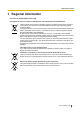
1 Regional Information 1 Regional Information For users in the European Union only Information for Users on Collection and Disposal of Old Equipment and used Batteries These symbols on the products, packaging, and/or accompanying documents mean that used electrical and electronic products and batteries should not be mixed with general household waste.
1 Regional Information Additional Information F.C.C. AND INDUSTRY CANADA RELEVANT INFORMATION CAUTION Any changes or modifications not expressly approved by the party responsible for compliance could void the user’s authority to operate this device. Privacy of communications may not be ensured when using this unit. Notice FCC ID can be found on the back of this unit. Note This equipment has been tested and found to comply with the limits for a Class B digital device, pursuant to Part 15 of the FCC Rules.
1 Regional Information interference is experienced, move the wireless telephone further away from the TV or VCR. This will often reduce, or eliminate, interference. Notes • The screen shots shown in this guide are provided for reference only, and may differ from the screens • displayed on your PC. The contents and design of the software are subject to change without notice.
2 Overview 2 Overview Outline This document describes the installation, deployment, configuration of a DECT system that works with the Panasonic IP-PBX. In this system, DECT 6.0 Portable Stations are used together with IP Cell Stations. Related Documentation Important Information Describes the safety precautions to prevent personal injury and/or damage to property. Please refer to the following web site for more information: http://panasonic.
2 Overview – Easy maintenance using wireless download. Activation Key Code and Key Management System To obtain additional activation keys, you need to purchase the appropriate activation key codes and access the Key Management System. You can download the activation keys as an activation key file from the Key Management System. To download the activation keys, enter the MPR ID number shown on the back of the main unit, and activation key number and registration ID provided on each activation key code.
3 Installing the IP-CSs 3 Installing the IP-CSs 3.
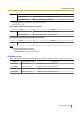
3 Installing the IP-CSs Amber *1 *2 ON Stand-by (unstable synchronization [no active calls]) Slow Flashing Talk (unstable synchronization [active calls]) Moderate Flashing Busy*2 (unstable synchronization) When the Activation Keys are applied, the Green color turns into Blue. All channels are occupied. IP-CS status indication during the site survey Color Red Status ON The IP-CS is connected to the AC adaptor. Moderate Flashing The IP-CS is connected to a PoE device.
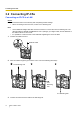
3 Installing the IP-CSs 3.2 Connecting IP-CSs Connecting an IP-CS to a LAN Notice • • Connect the units to the LAN only after completing network settings. When connecting a unit to the LAN, connect it to a switching hub. Note • Use an Ethernet straight cable with an RJ45 connector to connect the unit to a switching hub. The cable should be a 10BASE-T/100BASE-TX CAT 5 (Category 5) or higher cable, and the diameter of the cable must be 6.5 mm or less.
3 Installing the IP-CSs Connecting an AC Adaptor to an IP-CS The units comply with the IEEE 802.3af Power-over-Ethernet (PoE) standard. If PoE is available on your network, these units can receive the necessary power supply from the network through the network cable. In this case, no AC adaptor is needed for the units. However, if PoE is not available, you will need to connect an AC adaptor to the unit.
3 Installing the IP-CSs 3.3 Wall Mounting Mounting WARNING • • • Make sure that the wall that the unit will be attached to is strong enough to support the unit (approx. 330 g). If not, it is necessary for the wall to be reinforced. Only use the wall-mounting equipment included with the unit. When the unit is no longer in use, make sure to detach it from the wall.
3 Installing the IP-CSs Reference for Wall Mounting Please copy this page and use as a reference for wall mounting. Install a screw here. 83 mm Install a screw here. Note Make sure to set the print size to correspond with the size of this page. If the dimension of the paper output still deviates slightly from the measurement indicated here, use the measurement indicated here.
3 Installing the IP-CSs 3.4 Installing the Unified Maintenance Console System Requirements Required Operating System • Microsoft® Windows® XP, Windows Vista® Business, Windows 7, Windows 7 Professional, Windows 8 or Windows 8 Professional operating system Minimum Hardware Requirements • HDD: 100 MB of available hard disk space • The PC must fulfill the hardware requirements of the installed Microsoft Windows operating system.
3 Installing the IP-CSs 3.5 Initializing the IP-CS If the IP-CS does not operate properly, initialize the IP-CS. Before initializing the IP-CS, try the system feature again to confirm whether there definitely is a problem or not. The settings that are configured by using the IP Terminal Maintenance Console are changed back to their factory default by initializing the IP-CS. While initializing the IP-CS, calls cannot be made or received and ongoing conversations will be disconnected. 1.
4 Deployment Procedure 4 Deployment Procedure 4.1 Overview 4.2 Site Planning 4.3 Site Survey 4.4 Example of How to Conduct the Site Survey 4.5 Example of How to Make a Site Map 4.6 Basic Network Configuration 4.7 CS Registration 4.
5 Troubleshooting 5 Troubleshooting Quick Installation Guide 17
6 Appendix 6 Appendix 6.1 Specifications IP-CS Specification Type IP Cell Station Unit Supported Audio Narrowband Radio Method DECT 6.0 IP Port Number Flexible Setting Yes Local Setting Yes (through Web application) Site Survey Mode Yes Initialization Yes Maximum Simultaneous Calls 4, 8*1 Power Supply PoE (IEEE 802.3af Class2) Optional AC adaptor (KX-A239 [PQLV206]) VoIP Audio Codec G.711, G.729A, G.726 LAN Port 10 BASE-T 100 BASE-TX VLAN Yes (802.
6 Appendix Item Transmission Output Description Peak 250 mW CAUTION • • • • The IP-CS should be kept free of dust, moisture, high temperature (more than 40 °C), low temperature (less than 0 °C), and vibration, and should not be exposed to direct sunlight. The IP-CS should not be placed outdoors (use indoors). The IP-CS should not be placed near high-voltage equipment. The IP-CS should not be placed on a metal object. Compatible PSs Model No.
Panasonic System Networks Co., Ltd. declares that the unit is in compliance with the essential requirements and other relevant provisions of Radio Telecommunications Terminal Equipment (RTTE) Directive 1999/5/EC. Declarations of Conformity for the relevant Panasonic products described in this manual are available for download by visiting: http://www.ptc.panasonic.