PAN4620 IEEE® 802.15.4 and Bluetooth® Low Energy Module Module Integration Guide Rev.0.
PAN4620 Module Integration Guide Overview The PAN4620 is Panasonic’s Internet of Things dual mode module comprising NXP®’s Kinetis MKW41Z512CAT4 SoC - a 2.4 GHz 802.15.4 and ® Bluetooth Low Energy wireless radio ® microcontroller based on an ARM Cortex-M0+ core. Characteristics • Transceiver frequency range 2360 MHz to • • • 2483.5 MHz Programmable transmitter output power: -30 dBm to 3.5 dBm Receiver sensitivity (BLE): -95 dBm ® Receiver sensitivity typical for IEEE Standard 802.15.
PAN4620 Module Integration Guide By purchase of any of the products described in this document the customer accepts the document's validity and declares their agreement and understanding of its contents and recommendations. Panasonic Industrial Devices Europe GmbH (Panasonic) reserves the right to make changes as required at any time without notification. Please consult the most recently issued User Guide before initiating or completing a design. © Panasonic Industrial Devices Europe GmbH 2019.
PAN4620 Module Integration Guide Any outlined or referenced (source) code within this document is provided on an “as is” basis without any right to technical support or updates and without warranty of any kind on a free of charge basis according to § 516 German Civil Law (BGB) including without limitation, any warranties or conditions of title, non-infringement, merchantability, or fitness for a particular purpose. Customer acknowledges that (source) code may bear defects and errors.
PAN4620 Module Integration Guide Table of Contents 1 About This Document .................................................................................................................. 6 1.1 Purpose and Audience......................................................................................................... 6 1.2 Revision History .................................................................................................................. 6 1.3 Use of Symbols .......................
PAN4620 Module Integration Guide 1 About This Document 1 About This Document 1.1 Purpose and Audience This Integration Guide applies to the IEEE® 802.15.4 and Bluetooth® Low Energy development platform PAN4620 USB. The intention is to enable our customers to easily integrate our module PAN4620 in their product and to ensure compliance with regulatory requirements. This guide describes the hardware by giving a reference design, which is an evaluation board for the PAN4620.
PAN4620 Module Integration Guide 1 About This Document Symbol Description This font GUI text Indicates fixed terms and text of the graphical user interface. Example: Click Save. Menu > Menu item Path Indicates a path, e.g. to access a dialog. Example: In the menu, select File > Setup page. This font File names, messages, user input Indicates file names or messages and information displayed on the screen or to be selected or entered by the user. Examples: pan1760.
PAN4620 Module Integration Guide 2 Overview 2 Overview The PAN4620 USB is a development platform for the PAN4620 IEEE® 802.15.4 and Bluetooth® Low Energy module to implement Bluetooth and IEEE® 802.15.4 functionality into various electronic devices. Please refer to the Panasonic website for related documents 8.1.2 Product Information. Module Integration Guide Rev.0.
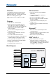
PAN4620 Module Integration Guide 3 PAN4620 Module 3 PAN4620 Module 3.1 Block diagram PAN4620 IEEE 802.15.4 and Bluetooth Low Energy 4.2 Module VCC 1.8 V - 4.2 V Reset GPIOs UART NXP KW41Z Crystal 32 MHz SPI I²C ADC Flash 512 kB Crystal 32.768 kHz Chip Antenna DAC TSI SRAM 128 kB SWD 3.2 Footprint Top view (dimensions are in mm) Module Integration Guide Rev.0.
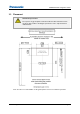
PAN4620 Module Integration Guide 3 PAN4620 Module 3.3 Placement Antenna Keep-out Area Do not place any ground plane under the marked restricted antenna area in any layer! This would be affecting the performance of the chip antenna in a critical manner. Note: The above recommendation for the ground plane is based on a FR4 4-Layer PCB. Module Integration Guide Rev.0.
PAN4620 Module Integration Guide 3 PAN4620 Module Antenna Keep-out Area The antenna requires a cutout area of 5 mm x 3 mm under the PAN4620 module. This keep-out area shall be located in every layer under the module antenna. Note for example the keep-out area in all four layers of the PAN4620 evaluation board. Impact of Placement on the Antenna Radiation Pattern The placement of the module, surrounding material, and customer components have an impact on the radiation pattern of the antenna.
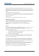
PAN4620 Module Integration Guide 4 Reference Design 4 Reference Design 4.1 Block diagram Module Integration Guide Rev.0.
+5V 1µ C1 TP5 TP3 TP4 TP1 1 6 EN VIN IC1 3 4 5 +3V3 R1 TP6 LD39100PU33R PG VOUT NC For programming SAM3U2C TP2 GND GND 2 EXP 4k7 1µ C3 100nF DP1 DM1 100nF C12 100nF C8 4µ7 100nF 18pF C7 X1 R7 R6 10µ C11 TP8 TP7 0 10nF 39 1% 39 1% 18pF C10 12MHz R8 C9 C6 C2 R2 C5 4k7 R3 100nF 100k C4 4k7 R4 +3V3 +3V3 R5 www.segger.
VBUS DM DP ID GND SW1 1 2 3 4 5 x M_3V3 10 11 12 1 2 3 4 5 6 7 8 9 JP2 M_RESET +3V3 +1V8 PC2 PC3 PC5 PA0 PA1 UART1 CTS UART1 RTS UART1 TXD UART1 RXD GND 2 1 BLM15BB121SN1 L2 R19 +3V3 100nF C19 1 3 4 6 2 4 1 2 3 4 2 4 6 8 R25 100 R24 100 R23 100 R22 100 R21 100 VP 1 3 RESET_OB IoT UART JP7 SWDIO_OB SWDCLK_OB JP4 2 4 1µ 35 34 11 32 33 31 30 27 26 1µ 100nF C28 R29 BYPASS XTALIN/CLKIN USBDP_UP USBDM_UP VBUS_DET C4 C5 RBIAS PLLFILT TEST XTALOUT PAN4620 ADC0/DP0
PAN4620 Module Integration Guide 4 Reference Design 4.3 Placement Recommendations The module shall be placed as close as possible to the edge of the application. It is important to have the keep out area below the antenna. Keep out area To download the design files go to the download area on the product website. 8.1.2 Product Information. 4.4 Building Blocks Module Integration Guide Rev.0.
PAN4620 Module Integration Guide 4 Reference Design 4.5 Breakout pins Module Integration Guide Rev.0.
PAN4620 Module Integration Guide 4 Reference Design 4.6 Configuration Settings Jumper Description J1 5 V from USB connected 5 V from or to breakout pin connected J3 Module reset connected Module reset disconnected J4 SWD connected 5 V power option, to power the board from USB or the 5 V pin. The 5 V from USB can also be used to power the sensor board. If there is no firmware on the module, the reset will be pulled low.
PAN4620 Module Integration Guide 4 Reference Design Module UART disconnected J9 Module VCC connected. Module VCC connection and GND pin. The module VCC jumper can be removed for current measurements. J7, J10 FTDI connected to module UART. Option for module UART to breakout pin or FTDI. Place jumpers either on J7 or J10. Breakout pin connected to module UART. 3.3 V are supplied to the breakout pin. J11 3.3 V are not supplied to the breakout pin.
PAN4620 Module Integration Guide 4 Reference Design 4.7 PCB Layout 4.7.1 Top Layer 4.7.2 Second Layer Module Integration Guide Rev.0.
PAN4620 Module Integration Guide 4 Reference Design 4.7.3 4.7.4 Third Layer Bottom Layer Module Integration Guide Rev.0.
PAN4620 Module Integration Guide 5 Getting Started 5 Getting Started 5.1 Jumper Start up Configuration Place all highlighted jumpers on PAN4620 evaluation board. Connect the device via USB cable to a PC, to power it and run demo examples. Module Integration Guide Rev.0.
PAN4620 Module Integration Guide 5 Getting Started 5.2 Device Drivers 5.2.1 General It might be necessary to install drivers for some components. Please note that the “FTDI USB UART” and the “Segger J-Link” SWD debugger will provide COM ports to the system. On the PAN4620 USB evaluation board both COM ports can be used to open a UART connection to the PAN4620 module. 5.2.2 FTDI USB UART Having the drivers installed correctly is mandatory for all the examples mentioned in this Quick Start Guide.
PAN4620 Module Integration Guide 5 Getting Started 5.3 Using Initial Bluetooth Heart Rate Example on PAN4620 USB The PAN4620 evaluation board is coming with preinstalled Bluetooth Low Energy demo example. Run the first demo 1. Download the app IoT-Toolbox from Google Play or Apple iTunes Store. 2. Start the app IoT-Toolbox. 3. Select the icon Heart Rate. 4. Switch on Bluetooth on Smartphone/Tablet. 5. Press the button SW3 on PAN4620-ETU to start advertising. 6. Scan for devices on Smartphone/Tablet.
PAN4620 Module Integration Guide 5 Getting Started 8. Press the button SW2 on the PAN4620-ETU to send changed heart rate data. See heart rate changes on Smartphone/Tablet. 5.4 Getting NXP MCUXpresso IDE for PAN4620 Module The following requirements must be met: Created user account on NXP website 1. Visit the website www.nxp.com. 2. Search for MCUXpresso Integrated Development Environment (IDE)and download it. NXP will lead to the following page. Module Integration Guide Rev.0.
PAN4620 Module Integration Guide 5 Getting Started 3. Click Sign in. 4. Download the preferred MCUXpresso IDE version and install the IDE. 5.5 Getting NXP SDK for PAN4620 Module Getting necessary sources for software development 1. Visit the website www.nxp.com. 2. Search for MCUXpresso SDK Builder. 3. Click Select Development Board to search for the correct board or kit to get started. The PAN4620-ETU is based on the FRDM-KW41Z platform from NXP. Module Integration Guide Rev.0.
PAN4620 Module Integration Guide 5 Getting Started 4. Enter FRDM-KW41Z to the field Search by Name (1). 5. Select the found board (2). 6. Enter a preferred name for the SDK (3). 7. Click on Build MCUXpresso SDK (4). The regulatory testing of PAN4620 was done using SDK version 2.2.0 with release date 2019-04-24, to not risk voiding the precertification of the module and to avoid problems during regulatory testing we strongly recommend to use exactly this version of the SDK. SDK version: 2.2.
PAN4620 Module Integration Guide 5 Getting Started 3. Click Add software component (3) and select optional Middleware. Available are middleware like CMSIS DSP Lib, FatFS, mbedtls, NTAG I2C, wolfssl, FreeRTOS operating system and wireless stacks like 802.15.4 MAC, Bluetooth LE, GenFSK, SMAC, Thread and Zigbee. 4. Click Download SDK (4). The SDK Details will show that SDK version 2.2.0 is available. Module Integration Guide Rev.0.
PAN4620 Module Integration Guide 5 Getting Started 5.6 Using SDK in MCUXpresso IDE To get access to the sources in the SDK, it is necessary, to link the SDK to the IDE. 1. Open MCUXpresso IDE (v10.3.1_2233). 2. Pull the folder (zipped or unzipped) into the tab Installed SDKs in MCUXpresso IDE. For further information about getting started with the API, the middleware and examples for wireless stacks, see the documentation folder in the SDK (SDK_2.2.0_FRDM-KW41Z > docs).
PAN4620 Module Integration Guide 5 Getting Started 2. Select the previously loaded SDK frdmkw41z (1). 3. Click Next > (2). Run the software 1. Select the preferred example for running a demo. 2. Enter a Project name suffix (1) to distinguish between different programs in the workspace. 3. Click Browse (2) to select the location for the project (usually, the predefined workspace).
PAN4620 Module Integration Guide 5 Getting Started 5. Click Finish (1). Compile the example project 1. Click onto the project inside the Project Explorer (1) within MCUXpresso IDE. 2. Click the Build icon project. Module Integration Guide Rev.0.
PAN4620 Module Integration Guide 5 Getting Started MCUXpresso IDE after starting the debug process. Flash the software 1. Connect the PAN4620 evaluation board to the PC. 2. Click the Debug icon (1). The software will be flashed with the onboard J-Link-OB-SAM3U128 to the PAN4620 module. Wait till this process is finished. 3. Click the Start icon evaluation board. Module Integration Guide Rev.0.
PAN4620 Module Integration Guide 5 Getting Started In case of more than one connected PAN4620 board, the IDE will give the possibility, to choose which one should be flashed. Compare the Segger Serial number/ID (1) with the label on the bottom of the PAN4620 board. Click OK (2). 5.7 Using Test Tool 12 Another way to flash a previously written program to the PAN4620 device is the Test Tool 12 provided by NXP. The following requirements must be met: NXP account 1. Go to NXP website (www.nxp.com). 2.
PAN4620 Module Integration Guide 5 Getting Started After windows driver installation the device with COM port will show up in window Command Console (1). 2. Click on the tab Firmware Loader (2). 3. Select the preferred J-Link device in the list (1). The label on the bottom of the PAN4620 ETU device will give the Segger J-Link ID of the board, which can be found in the mentioned list. Module Integration Guide Rev.0.
PAN4620 Module Integration Guide 5 Getting Started 4. Click browse (2). 5. Navigate to the file, which should be flashed on the PAN4620 ETU device. The file must be in *.srec or in *.bin format. There are two options: The first option is to generate the mentioned files in an Integrated Development Environment (IDE) like IAR Embedded Workbench or MCUXpresso from NXP. The second option is to use some of the already generated files that are available in the NXP SDK (see folder path: SDK_2.2.
PAN4620 Module Integration Guide 5 Getting Started 1. Click Upload (1). 2. Select the controller KW41Z (2), which is used on PAN4620 device. 3. Click OK (3). The Test Tool 12 will flash the program to the PAN4620. Now the previously written application can be evaluated and used. Next to the Firmware Loader option, the NXP Test Tool 12 comes with additional functions like a Protocol Analyzer, a Radio Test or an OTA (Over The Air) Update section.
PAN4620 Module Integration Guide 5 Getting Started Wait till the node has created the Thread network (here with the ID 0xc26d). 3. On the second node enter the command thr join and press Enter . The node will search for existing Thread networks (RGB LED5 will change colors fast) and connect to the previously created network automatically. Module Integration Guide Rev.0.
PAN4620 Module Integration Guide 5 Getting Started 4. Press SW2 on both PAN4620-ETU nodes, to change the color of the RGB LEDs on both nodes. Thread network is working. 5. Press the button SW3. Everything within the software is prepared and implemented to exchange the measured temperature between the nodes. Get more information about the possibilities and commands, in Thread networks, with the commands help and help thr. Please note that there is no thermistor mounted on the PAN4620-ETU.
PAN4620 Module Integration Guide 6 Regulatory and Certification Information 6 Regulatory and Certification Information Regulatory certification / tests were done using: SDK version 2.2 BT version 1.2.X IEEE 802.15.4 version X??? The RF synthesizer within the PAN4620 can be configured to use any channel frequency between 2.36 GHz and 2.487 GHz. However, the information given in 6 Regulatory and Certification Information is only valid within the ISM frequency band starting at 2.4 GHz.
PAN4620 Module Integration Guide 6 Regulatory and Certification Information { testChannel = (channels_t)gTotalChannels; } else { testChannel--; } if((testChannel == 26)&&(testPower > 18)){ testPower = 18; } break; case 'a': testPower++; if(testChannel == 26){ if((0x12 ) < testPower) { testPower = gMinOutputPower_c; } }else{ if(gMaxOutputPower_c < testPower) { testPower = gMinOutputPower_c; } } break; case 's': if(testChannel == 26){ if(testPower == gMinOutputPower_c) { testPower = 0x12; } else { testPow
PAN4620 Module Integration Guide 6 Regulatory and Certification Information The OEM must ensure that FCC labelling requirements are met. This includes a clearly visible label on the outside of the OEM enclosure specifying the appropriate Panasonic FCC identifier for this product as well as the FCC Notice above. The FCC identifier is FCC ID: T7V4620. This FCC identifier is valid for the PAN4620. The end product must in any case be labelled on the exterior with: "Contains FCC ID: T7V4620" 6.
PAN4620 Module Integration Guide 6 Regulatory and Certification Information French Obligations d’étiquetage Les fabricants d’équipements d’origine (FEO) – en anglais Original Equipment Manufacturer (OEM) – doivent s’assurer que les obligations d’étiquetage IC du produit final sont remplies. Ces obligations incluent une étiquette clairement visible à l’extérieur de l’emballage externe, comportant l’identifiant IC du module Panasonic inclus, ainsi que la notification ci-dessus.
PAN4620 Module Integration Guide 7 Cautions 7 Cautions 7.1 Restricted Use 7.1.
PAN4620 Module Integration Guide 8 Contact Details 8 Contact Details 8.1.1 Contact Us Please contact your local Panasonic Sales office for details on additional product options and services: For Panasonic Sales assistance in the EU, visit https://eu.industrial.panasonic.com/about-us/contact-us Email: wireless@eu.panasonic.com For Panasonic Sales assistance in North America, visit the Panasonic Sales & Support Tool to find assistance near you at https://na.industrial.panasonic.