
Integration Guide


PAN4620 Module Integration Guide
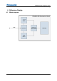
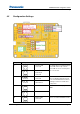
4 Reference Design
Module Integration Guide Rev.0.1 Page 18
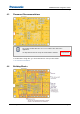
Module UART
disconnected
J9
Module VCC
connected.
Module VCC connection and GND
pin. The module VCC jumper can be
removed for current measurements.
J7, J10
FTDI connected to
module UART.
Option for module UART to breakout
pin or FTDI. Place jumpers either on
J7 or J10.
Breakout pin
connected to module
UART.
J11
3.3 V are supplied to the
breakout pin.
Option to power an
external sensor board
sensors with 3.3 V. Do not
place this jumper, if an
external 3.3 V source is
present.
3.3 V are not supplied to
the breakout pin.
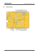
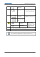
R32, R48
These 0 Ω resistors can be removed, to disconnect the LEDs in case the IOs PTB0,
PTC1, PTA18, and PTA19 shall be used for other purposes.
SW2, SW3
If you want to use PTC4 and PTC5 for other purposes, do not push the buttons.
After each different configuration the reset button needs to be pressed.