
User Manual

CLASSIFICATION
PRODUCT SPECIFICATION
No.
DS-9320-2400-102
REV.
1.1
SUBJECT
WI-FI IEEE 802.11 BGN FULL EMBEDDED MODULE
PAGE
8 of 43
CUSTOMER’S CODE
PAN9320 / PAN9310
PANASONIC’S CODE
ENW49A01x3EF & ENW49A02x3EF
DATE
14.03.2016
PANASONIC INDUSTRIAL DEVICES EUROPE GMBH
www.pideu.panasonic.de
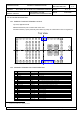
10. DETAILED DESCRIPTION
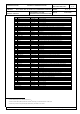
10.1. PAN9320 / PAN9310 TERMINAL LAYOUT
Top View, Application PCB
PAN9310 RF bottom pad is marked with a blue circle
Command UART0 (2 pads) and binary data UART1 (4 pads) are marked with a blue rectangular box
36 22
Top View
151
16
17
18
19
20
21
42
41
40
39
38
37
Chip
Antenna
F1 F2 F3 F4 F5
E1 E2 E3 E4 E5
D1 D2 D3 D4 D5
C1 C2 C3 C4 C5
B1 B2 B3 B4 B5
A1 A2 A3 A4 A5
2 3 4 5 6 7 8 9 10 11 12 13 14
35 34 33 32 31 30 29 28 27 26 25 24 23
GND
THERMO
GND
THERMO
GND
THERMO
GND
THERMO
10.2. COMMON TERMINAL PIN-CONFIGURATION
No
Pin Name
Pin Type
Description
1
GND
Ground Pin
Connect to Ground
2
GPIO44
1
Digital I/O
Digital I/O #44
3
GPIO45
1
Digital I/O
Digital I/O #45
4
USB AVDD 33
Power
Don’t connect, only for internal purpose
5
NC
NC
Don’t connect
6
NC
NC
Don’t connect
7
3.3V
Power
3.0V – 3.6V power supply connection (typical 3.3V)
8
3.3V
Power
3.0V – 3.6V power supply connection (typical 3.3V)
9
UART1 CTS
Digital In
CTSn for UART1 (using hardware flow control)
10
UART1 RTS
Digital Out
RTSn for UART1 (using hardware flow control)
11
UART1 TXD
Digital Out
TXD for UART1
12
UART1 RXD
Digital In
RXD for UART1
13
QSPI CS2
4
Digital Out
Chip select external flash (connect for usage of external QSPI flash memory)
14
GND
Ground Pin
Connect to Ground
15
GND
Ground Pin
Connect to Ground
16
NC / RF
NC / Analog IO
PAN9320: NC / PAN9310: RF in/out over 50 bottom pad
17
GND
Ground Pin
Connect to Ground
18
GND
Ground Pin
Connect to Ground
19
GND
Ground Pin
Connect to Ground
20
GND
Ground Pin
Connect to Ground
21
GND
Ground Pin
Connect to Ground
1
All GPIO’s are initially set to output with low level