
User's Manual
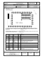


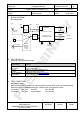
Table Of Contents
- KEY FEATURES
- APPLICATIONS FOR THE MODULE
- DESCRIPTION OF THE MODULE
- SCOPE OF THIS DOCUMENT
- HISTORY FOR THIS DOCUMENT
- TERMINAL LAYOUT
- BLOCK DIAGRAM
- KEY PARTS LIST
- TEST CONDITIONS
- ABSOLUTE MAXIMUM RATINGS
- OPERATING CONDITIONS
- DC ELECTRICAL CHARACTERISTICS
- A/D CONVERTER CHARACTERISTICS
- AC ELECTRICAL CHARACTERISTICS
- MECHANICAL REQUIREMENTS
- SOLDERING TEMPERATURE-TIME PROFILE (FOR REFLOW SOLDERING)
- MODULE DIMENSIONS
- FOOT PRINT OF THE MODULE
- LABELING DRAWING
- RECOMMENDED LAND PATTERN
- SOFTWARE
- RELIABILITY TESTS
- APPLICATION NOTES
- PACKAGING
- ORDERING INFORMATION
- ROHS DECLARATION
- DATA SHEET STATUS
- REGULATORY INFORMATION
- RELATED DOCUMENTS
- GENERAL INFORMATION
- LIFE SUPPORT POLICY

CLASSIFICATION
Einstufung
PRODUCT SPECIFICATION
Produktspezifikation
No.
DS-ETR2-2400-102
REV.
D
SUBJECT
Thema
MODEM FOR IEEE802.15.4 (ZIGBEE)
“ZigBee” Modem“ (IEEE802.15.4)
PAGE
Seite
7 of 29
CUSTOMER’S CODE
ETRX2
PANASONIC’S CODE
ENWC9A0xyzE
DATE
Datum
01.08.2006
HIGH FREQUENCY PRODUCTS DIVISION
Module Business
PANASONIC ELECTRONIC DEVICES
(EUROPE) GmbH
APPROVED
genehmigt
CHECKED
geprüft
DESIGNED
erstellt
6. TERMINAL LAYOUT
Anschlußbelegung
The table below informs about the 38 module pin signals for direct SMD soldering of ETRX2 to
the application board. The signal names are identical to the signal names of EM250, except for
RF and VC1.
The pin numbers in brackets () are the related pins of the pin/header connector X5, which is only
mounted for special plug versions.
Pin
No.
Pin
Name
Signal
Name
Pin
Type
Description
1(3) GND1 GND I/O ground
2 RF RF I/O RF input/output terminal
3 GND3 GND I/O ground
4(1) GPIO0
GPIO0
MOSI
MOSI
TMR1IA.1
I/O
O
I
I
Digital I/O
SPI master data out of serial controller SC2
SPI slave data in of serial controller SC2
Capture Input A of Timer 1
5(2) REG_OUT REG_OUT O output of EM250 regulator voltage VREG_OUT
(1)
6 GND2 GND I/O ground
7(10) VBAT VBAT I module dc supply voltage
8 GND3 GND I/O ground
9(4) GPIO4
GPIO4
ADC0
PTI_EN
I/O
Analog
O
Digital I/O
ADC Input 0
Frame signal of Packet Trace Interface (PTI)