
User Manual


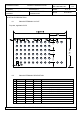


Table Of Contents
- 1 SCOPE OF THIS DOCUMENT
- 2 KEY FEATURES
- 3 BLUETOOTH LOW ENERGY
- 4 APPLICATIONS FOR THE MODULE
- 5 DESCRIPTION FOR THE MODULE
- 6 DETAILED DESCRIPTION
- 7 BLUETOOTH FEATURES
- 8 BLOCK DIAGRAM
- 9 TEST CONDITIONS
- 10 GENERAL DEVICE REQUIREMENTS AND OPERATION
- 11 BLUETOOTH RF PERFORMANCE
- 12 SOLDERING TEMPERATURE-TIME PROFILE (FOR REFLOW SOLDERING)
- 13 MODULE DIMENSION
- 14 PAN1026 FOOTPRINT OF THE MODULE
- 15 CASE MARKING
- 16 MECHANICAL REQUIREMENTS
- 17 RELIABILITY TESTS
- 18 CAUTIONS
- 19 PACKAGING
- 20 ORDERING INFORMATION
- 21 INFORMATION REGARDING SOFTWARE VERSIONS
- 22 SOFTWARE
- 23 SOFTWARE BLOCK DIAGRAM
- 24 ROHS AND REACH DECLARATION
- 25 DATA SHEET STATUS
- 26 HISTORY FOR THIS DOCUMENT
- 27 RELATED DOCUMENTS
- 28 GENERAL INFORMATION
- 29 REGULATORY INFORMATION
- 30 INDUSTRY CANADA CERTIFICATION
- 31 EUROPEAN R&TTE DECLARATION OF CONFORMITY
- 32 LIFE SUPPORT POLICY

CLASSIFICATION PRODUCT SPECIFICATION
No.
DS-1026-2400-102
REV.
0.3
SUBJECT
CLASS 2 BLUETOOTH LOW ENERGY
SPP MODULE
PAGE 10 of 35
CUSTOMER’S CODE
PAN1026
PANASONIC’S CODE
ENW89837AxKF
DATE 02.10.2013
PANASONIC INDUSTRIAL DEVICES EUROPE GMBH www.pideu.panasonic.de
6.3.3 Frame Format
TC35661 supporting format is as follows.
Number of data bits: 8 bits
Parity bit: no parity
Stop bit: 1 stop bit
Flow control: RTS/CTS
UART data frame
6.3.4 Flow Control Function
TC35661 UART interface uses flow
control function by hardware signal, Transmit flow
control (CTSX) and receive flow control (RTSX). Above Figure shows signals input and
output direction .
CTSX input signal is used for UART transmitting. Low input indicates close of the
preparation of the other party to receive data and TC35661 executes UART transmitting
data if there is data for transmission. In case of input high level, TC35661 stops transmitting
by UART frame.
RTSX input signal is used for UART receiving. Low output indicates request data
transmission to UART transmit side device of the other party. TC35661 outputs Low level
from RTSX when being able to receive data and prepares to receive data.
Response time of UART transmitting and receiving for flow control signal depends on baud
rate and internal process status of frame. It is from 1 frame to 4 frames.
6.3.5 UART Baud Rate Setting
TC35661 UART interface has a programmable baud rate setting function. The UART baud
rate can be set according to the following equation. The baud rate generating clock
frequency is set to either 39 MHz or 52 MHz. The over-sampling number is set to an integer
UART Transmit data
UART Transmit
flow control
1
LSB 2 3 4 5 6 MSB
Start bit Stop bit
1 23456789 1
UART Receive flow
control
UART Receive data
1
LSB 2 3 4 5 6 MSB
Start bit Stop bit
OverSampling (*12 to17) /bit