03 Professional Models Panasonic Service and Technology Company 103FHD_USA 11OCT06 Technical Guide 103” Plasma Display Monitor National Training
103 Professional Models Panasonic Service and Technology Company 103FHD_USA 11OCT06 Prepared by Jean Magloire Panasonic Service and Technology Company National Training Copyright © 2005 by Panasonic Services Company All rights reserved. Unauthorized copying and distribution is a violation of law. Warning This service information is designed for experienced repair technicians only and is not designed for use by the general public.
103 Professional Models Table of Contents 103FHD_USA 11OCT06 Subject Page # Subject Page # Installation and Construction 5 Simplified Block Diagram 36 Preparation of Installation using Pedestal Stand 6 Picture signal flow 38 Electrical Work 7 Panel Drive (Basic Circuit) 40 Drawing of Installation with Pedestal Stand 8 Picture signal flow 42 Pictures of Installation with Pedestal Stand 9 Troubleshooting for signal symptom 47 Pictures of Plasma unit and Eye bolts 11 Relationship o
Table of Contents (Continued) 103 Professional Models 103FHD_USA 11OCT06 Subject Page # DS board SOS Circuit _ Power LED blinks 10 times 86 FAN SOS _ Power LED blinks 11 times 87 DN board SOS Power LED blinks 13 times 88 Alignment Procedure 89 Driver Setup 90 Driver Setup Voltages 91 Initialization Pulse Adjustment 92 Quick adjustment after P.C.B.
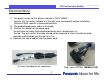
103 Professional Models Installation and Construction Pedestal Stand Installation & Construction - preparation - electrical work - installation procedure - pedestal stand assembly 5 103FHD_USA 11OCT06
103 Professional Models Preparation of Installation using Pedestal Stand 103FHD_USA 11OCT06 Pedestal Stand (TY-ST103PF9) 1) The power source is to be 240V – 1550W 2) Floor strength is to be more than 500kg/m2 (102.408lb/ft2). To avoid damaging the floor, prepare an underlay board, more than 15mm (0.6”) thick and larger than the size of the bottom stand to disperse load. 3) To prevent personal injury or damage on goods, the following measures must be taken.
103 Professional Models 103FHD_USA 11OCT06 Electrical Work 1) The power source for this plasma monitor is 240V-1550W. Confirm that the source voltage is of the right level and capacity before installation. (Electrical Work requires a licensed electrician) 2) The prepackaged power cable is 3m length. 3) Confirm the location of the power cord. Do not allow the cable to be pinched between walls, forcedly bent, or twisted.
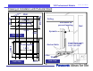
103 Professional Models 103FHD_USA 11OCT06 Drawing of Installation with Pedestal Stand 120 1,659.4 Ceiling 870.2 405 226 Wall Anchor Bolts Wire/chain to prevent toppling 2,270 Wall Eyebolts 305.3 1,626.8 Aerial View Anchor Bolts Prevent toppling 1,512 Floor Wheels Front View Side View 377.3 8 Keep 120mm space, so the rear stand cover can slide.
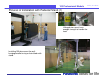
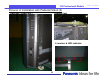
103 Professional Models 103FHD_USA 11OCT06 Pictures of Installation with Pedestal Stand (1) Lifting devices must have enough strength to handle the load. Installing 103 plasma on the wallhanging bracket using a chain-block with stand.
3 Professional Models Pictures of Installation with Pedestal Stand (2) Eyebolt (top) Switches (Power etc.
103 Professional Models Pictures of Plasma unit and Eye bolts) Slot (Interchangeable terminal) 11 103FHD_USA 11OCT06
103 Professional Models Pictures of Eyebolt Cap unit and Power Inlet) Power inlet Eyebolt cap (side) 12 103FHD_USA 11OCT06
103 Professional Models 103FHD_USA 11OCT06 Pictures of Stand Hook and Location for Eyebolt Stand-hook Stand-hook position for Pedestal (default) Eyebolt can be fixed here Stand-hook position for wall-hanging / anti-toppling (default : sealed by eyebolt cap) 13
103 Professional Models 103FHD_USA 11OCT06 Rear Panel and Vertical Installation Rear panel This side will be the upper side when the unit is Installed vertically (with exhaust fan) 14
103 Professional Models Wall Mount Installation Wall Mount Installation 15 103FHD_USA 11OCT06
103 Professional Models 103FHD_USA 11OCT06 Pedestal Stand (TY-ST103PF9) Horizontal Installation Vertical Installation 16
103 Professional Models 103FHD_USA 11OCT06 Preparation 1) Power requirement is 240V-1550W. (refer : “Electrical Work”) 2) Keep more than 300mm of empty space from the top and both sides of the unit. Keep more than 200mm from the rear cover of the Plasma to maintain the ambient temperature at 40 degree C or less. Moreover, it is recommended to keep more than 700mm maintenance space at the backside.
103 Professional Models 103FHD_USA 11OCT06 Wall Hanging Bracket (Horizontal) Building Frame Size Ceiling 1706 Wall Ceiling 120 Keep 300mm space for ventilation 200 1421 1421.2 200 Access Hole 733 113.1 Winch or chain block only when maintenance is offered Front View 175.1 Iron structure (H-frame etc.) 451.1 1512 200 451.1 2414.2 Maintenance space more than 700mm Iron structure (H-frame etc.
103 Professional Models 103FHD_USA 11OCT06 Wall Hanging Bracket (Vertical) Building Frame Size Winch or chain block only when maintenance is offered Front View Wall Keep 300mm space for ventilation 2414 1,521 Access Hole 224 849 Iron structure (H-frame etc.) 357.1 120 451.1 2,414.2 451.1 Ceiling 733 200 200 63.1 225.1 200 Maintenance space more than 700mm 1421.2 Iron structure (H-frame etc.
103 Professional Models 103FHD_USA 11OCT06 103 Servicing Requirements • • • • ON- Site Service Panasonic Broadcast Field Engineers Migrate to additional servicing facilities Free Access to back of plasma – 24-36 inches access – Includes power up access 20
103 Professional Models 103FHD_USA 11OCT06 Servicing Requirements (1) 21
103 Professional Models 103FHD_USA 11OCT06 Servicing Requirements (2) F A N S F A N S Vents along perimeter 22
103 Professional Models 103” PDP easy facts (1 of 3) Specifications: Weight : 500 lbs unpacked 1,000 lbs crated 280 lbs for Pedestal mount, 55 lbs for wall mount Size: 95” x 56” Power: 220V AC +/- 10% single phase, 9 ft long power cord 1,550 W Vertical Installation: Panasonic logo on the left side Choice of pedestal or wall mount Ventilation: factory recommends clearance: - 12” top and both sides - 8” back For wall mount installations: the supporting structure should support 5 x total weight = 5x 555 lbs
103 Professional Models 103” PDP easy facts (2 of 3) Delivery and Installation: Panasonic will ship the PDP using NVC Logistics company We recommend that NVC will provide the following services: -site survey for delivery purposes -Delivery, uncrate, dispose of crating materials -Transport the PDP to mounting location -Test PDP for functionality -Install PDP on pedestal (not on wall mount) Wall mount or custom installations: We recommend that the System Integrator that reinforces the structure is responsib
103 Professional Models 103FHD_USA 11OCT06 103” PDP easy facts (3 of 3) Delivery and Installation Pricing: -DSM/Rep to fill in attached questionnaire detailing level of Service requested, and email to Steve Beck, copy Theodore Radu -Steve Beck will then provide a quote for delivery/Installation -From Customer’s prospective: it is a Panasonic charge labeled as Freight -Panasonic and NVC do not take any responsibility for reinforcing the structure (wall or floor) Recommended action for wall/custom installa
103 Professional Models Intentionally Blank 103FHD_USA 11OCT06
103 Professional Models Chassis structure 27 103FHD_USA 11OCT06
103 Professional Models Back Covers 103FHD_USA 11OCT06 The unit contains 6 back covers that provide access to different areas of the board assembly.
103 Professional Models Back Covers 103FHD_USA 11OCT06 The unit contains six back covers that provide access to different areas of the board assembly. The areas are designated as zones that contain a specific set of boards. Zone 1 contains the SC, SU, SM, SD, C1, CZ, DR1, DR2 boards and a portion of the SC2 board. Zone 2 contains the PB, DS, DN, HX, HA, HDD, C2, C3, and one of the CD boards. Zone 3 contains the D, CD, C4, C5 and two CD boards.
Chassis Layout 103 Professional Models 103FHD_USA 11OCT06 The 103” plasma display monitor contains many more boards than the smaller size plasma display models that are on the market today. It contains: 1. Two P boards (power supply) 2. Twelve C boards (data drive) 3. There are six CD boards used to connect the D to the C boards 4. The SM board is added to complement the SU and SD of current models 5. There are four DR boards added to the unit, one at each corner, for Energy Data Recovery 6.
Boards and Part Numbers 103 Professional Models Board Name Function Board Name Function D Digital Signal Processor, Format Converter, Plasma AI Processor Sub-Field Processor CX Data Drive (X) CY Data Drive (Y) CZ Data Drive (Z) H5 Audio Out S1 Power Switch SS2 Sustain Out (Upper) SS3 Sustain Out (Lower) V1 LED_G, R DS Slot Interface (Audio / Video / Sync Input Switch), SYNC Processor, Audio Processor, Speaker Out Amplifier, DC-DC Converter 103FHD_USA 11OCT06 SS Sustain Drive V2
103 Professional Models Intentionally Blank 103FHD_USA 11OCT06
103 Professional Models Signal Circuit Explanation 33 103FHD_USA 11OCT06
103 Professional Models Simplified Block Diagram Signal Processor Input Source Panel Drive Video TV tuner AV terminal SD card PC input(*) Video Signal Brightness Contrast Sharpness etc Audio Signal Audio Bass Treble Balance Volume 34 Video Signal Picture Speaker Audio Signal Sound 103FHD_USA 11OCT06
103 Professional Models Simplified Block Diagram 103FHD_USA 11OCT06 Roughly speaking, the unit consists of three signal circuit blocks: 1. Input Source 2. Video and Audio Signal Processor with speaker output 3. Panel Drive The unit contains a permanent PC input and three card slots that can be used for different types of input signals. The signals may be in the NTSC, ATSC, DVI, HDMI, or SD format. After selection, the video signal is provided to the video signal process block of the unit.
103 Professional Models Picture signal flow LVDS Picture signal (Digital) DS DS IC5001 IC5001 LVDS LVDS Receiver Receiver SLOT 2 DVI IC3005 IC3005 Input Input Switching Switching SLOT 3 RGB Signal (Digital) DN SLOT 1 103FHD_USA 11OCT06 D IC9500 IC9500 IC5101 IC5101 ConvertIP IP Convert IC5002 IC5002 LVDS LVDS Receiver Receiver Convert Convert Format Format IC5402 IC5402 A/D A/D Additional Additional O.S.D. O.S.D.
103 Professional Models Picture signal flow 103FHD_USA 11OCT06 Slot 1 or Slot 2 may be used for component or DVI inputs. The drawing shows both connections for better understanding of the video selection and process of this unit. The DS board is an input board that contains 3 slot terminals. The Slot terminals may be used in conjunction with boards that facilitate NTSC, ATSC, RGB, DVI, and SD video input. Component, RGB or PC Video are input to the DS board and selected by IC3005.
103 Professional Models Panel Drive (Basic Circuit) 103FHD_USA 11OCT06 Panel Drive MPU IC9500 LVDS Receiver ・ Discharge Control IC9300 Subfield Data (Left half) Test Pattern D Picture Data CD Picture Data Picture Data CD CD C1 C2 C3 C4 C5 C6 SS2 SC SU IC9400 Sub Field Data (Right half) Test Pattern SS SM SD SS3 CZ Discharge Control (SCAN) Discharge Control (SUS) Picture Data CY CD Picture Data CD Picture Data EEPROM CD Panel Drive block Diagram 38 CX C9 C8 C7
103 Professional Models Panel Drive (Basic Circuit) 103FHD_USA 11OCT06 Discharge Control IC9500 of the D board contains the Discharge Control circuit that analyzes the RGB and sync information of the video signal to create the Scan data to drive the Scan operation (SC) board and Sustain data to drive the Sustain operation (SS) board. The SC board is responsible for the generation of the scan pulses. Scan pulses are used for initialization and selection of the pixels.
103 Professional Models Picture signal flow (1) 103FHD_USA 11OCT06 PANEL PANEL Driver Driver C1 Driver Driver Driver Driver Driver Driver Driver Driver ・・・・・・・・・・・・・・・・・・・・・・・・・・・・・・・・ Driver Driver Driver Driver Driver Driver C3 C2 CD DN D CD Buffer Buffer IC9400 IC9400 C4 Right Right CD CD IC9300 IC9300 Convertsub subfield field Convert Convertparallel parallelserial serial Convert Testpattern pattern Test C5 C6 Buffer Left Left Convertsub subfield field Convert Convertparallel pa
103 Professional Models Picture signal flow (1) 103FHD_USA 11OCT06 This diagram shows the panel drive boards that are connected to the D board. IC9300 and IC9400 provide data to six CD boards. IC9400 send picture data to both upper and lower CD boards that provide data to the left half of the panel. Conversely, IC9300 send picture data to both upper and lower CD boards that provide data to the right half of the panel. Each CD board supplies picture data to two C boards.
103 Professional Models Picture Signal flow (2) 103FHD_USA 11OCT06 Connection of C1~CZ board and PDP panel 1 1 1 1 1 1 1 ④ 1 ② 1 0 1 1 1 0 ③ 1 1 ① PDP panel 5.6” 2.
103 Professional Models Picture Signal flow (2) 103FHD_USA 11OCT06 There are 32 flexible cables that provide data drive signals to the panel, sixteen on the top and sixteen at the bottom of the panel . Two driver ICs are mounted on each flexible cable. Each driver IC provides data to 128 x 3 (RGB) lines of the panel. This is equivalent to addressing approximately 2.8” of the panel. The whole flexible cable addresses approximately 5.6” of the panel.
103 Professional Models Intentionally Blank 103FHD_USA 11OCT06
103 Professional Models Troubleshooting for signal symptom 45 103FHD_USA 11OCT06
103 Professional Models Relationship of board and display area DR2 103FHD_USA 11OCT06 DR1 Example of picture problems due to a defective board CD C6 C5 CD C4 CD C3 C2 DR2(1/4 of upper Left) C6 C1 SS2 SU SS SM SC C5 C4 DR1(1/4 of upper Right) C3 C2 C1 SU D board R L SC SS SM (all) SD SS3 C7 C8 CD C9 CD CX CY CZ SD C7 CD C8 C9 D( Left half) DR1(1/4 of lower left) CX DR2 46 CZ D( Right Half ) DR2(1/4 of lower right) D,DN, slot all DR1 CY (all)
103 Professional Models Relationship of board and display area 103FHD_USA 11OCT06 This picture shows the role of each board with respect to the display area. There are twelve C boards, six CD boards and four DR boards. Assuming you remember the board layout and function of each board. 1. If the C8 board is defective, picture information (black bar) will be missing from the center to the bottom area supplied by C8. This is due to the dual scan system. 2.
Picture Trouble (1) 103 Professional Models 103FHD_USA 11OCT06 ■Picture trouble(Vertical line all area, horizontal line, Color problem, Others) DN DS HDD LVDS Convert DVI Input HA Video Input Video Signal SW HX PC Input A/D Convert Picture Signal Processing Micro Computer OSD D I-P Convert Micro Computer Sub Field Data (Left half) Test Pattern Convert LVDS ・ Discharge Control CD CD C1 C2 C3 C4 C5 C6 SS2 SU SC SS SM Sub Field Data (Right half) Test Pattern Discharge control(SCAN) Disch
Picture Trouble (1) 103 Professional Models 103FHD_USA 11OCT06 This page covers the type of distortion one might notice in the picture. It is very easy to determine that a black bar on the screen is a panel drive problem. When we experience a color problem, it becomes somewhat difficult to determine whether the problem is due to a defect in the panel drive circuits or video processing circuit (DN board).
103 Professional Models Picture Trouble (2) 103FHD_USA 11OCT06 ■Picture trouble(Vertical line at part of screen, abnormal picture) Normal sound DR1 D Micro Computer ROM Convertsub subfield field Convert Convertparallel parallelserial serial Convert Testpattern pattern Test CD CD Convertsub subfield field Convert Convertparallel parallelserial serial Convert Testpattern pattern Test CD C1 C2 C3 C4 C5 C6 Sub Field Data (Left half) Test Pattern SC SU CD SS2 CD Buffer Buffer CD Buffer SS SM
103 Professional Models Picture Trouble (2) 103FHD_USA 11OCT06 The emphasis in this drawing is the type of defect one can expect from the boards that drive the panel or the panel itself. 1. One or more thin black lines from the top to the bottom of the panel is usually due to a D board defect. 2. No picture in either the left or right side of the panel is also caused by a D board defect. 3.
103 Professional Models Picture Trouble(3) DR1 Picture Data Picture Data D Micro Computer Picture signal Convert LVDS Control discharge Picture Data DR2 CD CD CD SIU VF Sub Field Data (Left half) Test Pattern C1 C2 C3 C4 C5 C6 VF SU SUS DRV SS2 VF0 SUS DRV SM Sub Field Data (Right half) Test Pattern SC SD VF0 CZ CY CX C9 C8 C7 Scan control San Drive SID Discharge control (SUS) Picture Data CD Picture Data PROM Picture Data CD CD DR2 DR1 ■Trouble sample ●Horizontal line at part of
103 Professional Models Picture Trouble(3) 103FHD_USA 11OCT06 The emphasis in this drawing is the type of defect one can expect from a scan operation problem. 1. One or more thin horizontal black lines are caused by a defective SU, SM, or SD board. 2. A horizontal black bar that occupies 1/3 of the screen is caused by a defective SU, SM, or SD board. 3. A totally black screen or a picture that is distorted throughout is caused by a defective SC or D board.
103 Professional Summary of Picture Trouble and defective boardModels 103FHD_USA 11OCT06 Diagnosis of board defect C1-CZ board DR1 Or CD board DR2 board C/CD/D board C/CD/D board SU/SM/SD board SU/SM/SD board Or Panel Colored vertical bar SU/SM/SD board 54 D board
103 Professional Models Picture trouble all area Picture Trouble (all areas) Video or PC DVI Do all the video Inputs provide the symptom? DN or DS board HDD board Video No 103FHD_USA 11OCT06 HA board PC HX board All input sources Do the Internal Test Patterns provide the same symptom? What is the symptom? NG Abnormal discharge SC/SS board OK Is the OSD visible on screen? OK DN board NG Group of vertical line SU/SM/SD board D board D or DN board Ex.
103 Professional Models Picture trouble (3) No picture, green power LED is lit. No Did the power relay click on? Replace the P or D board Video or PC Yes DVI Is there video from any of the inputs? Is there O.S.D? Replace the HDD board If there is no video from Video Replace the HA board PC No Replace the DN or DS board Replace the HX board Yes Replace the DN board No No picture Disconnect CN D5 and turn the unit on.
Picture Trouble (Vertical line) 103 Professional Models Panel Panel(IC (ICdriver) driver)defect defect PDP panel CCor orCD CDcircuit circuitdefect defect PDP panel 15cm approx.
103 Professional Models Intentionally Blank 103FHD_USA 11OCT06
103 Professional Models 103FHD_USA 11OCT06 Power Supply Circuit Explanation 59
Professional Models Power supply circuit (VDA and Low 103 Voltages) F LINE FILTER T0 F9 SC SIDE TO F8 SS SIDE P9 P 1 4 AC IN Line Filter Rectification Power Factor Control 395V Vda 75V 15V Vlow Stand-by STB5V 5V 60 F_STB_15V 103FHD_USA 11OCT06
Professional Models Power supply circuit (VDA and Low 103 Voltages) 103FHD_USA 11OCT06 The basic operation of the new P board is the same as that of the older Plasma Display Monitors. The Standby circuit supplies STB5V for system control operation and 5V for Panel operation. The main circuit supplies Vda voltage for data drive , 15V for sustain, scan, and fan operations. The F_STB_15V is used on the DS board to generate other operating voltages for the the video processing circuit.
103 Professional Models Power supply circuit (VSUS) 103FHD_USA 11OCT06 F LINE FILTER P9 P 1 4 AC IN Line Filter Rectification Power Factor Control 395V Vsus 185V Due to the amount of current required to drive this plasma display panel, a separate circuit is used to generate the VSUS voltage. Its basic operation is the same as previously used power supplies. The incoming AC voltage is filtered and rectified.
103 Professional Models Line Filter 103FHD_USA 11OCT06 The F board of the older Plasma Display Monitors is reintroduced in this model. The function of the line filter is to block incoming noise from the AC outlet to the unit and outgoing noise from the unit to the AC outlet. It provides two outputs that are connected to two separate but identical power supply boards. One of the power supply boards (P SC SIDE) is used to power the scan drive circuits and the other (P SS Side) the sustain drive circuit.
Power Supply Circuit Block Diagram103 Professional Models ●Power supply circuit diagram ①Main Power SW-ON P(SC) PC D DN STB_5V Stand by Circuit Tr ③STB_ON IC502/IC301 Power Relay IC9011 ④MAIN_ON MC701 Vlow/Vda Power circuit STB3.3V Reset F_STB_15V P+15V/ Vda Vsus IC9003 Micro Computer P(SS) Stand by Power Circuit IC201 STB_5V ⑤STB_ON IC502/IC301 Power Relay MC701 ⑤MAIN_ON ⑥F_STB_15V P+15V/ Vda Vlow / Vda Power Circuit IC201/IC202 Vsus Power Circuit IC4308 IC4704 STB3.
103 Professional Models Power supply Circuit 103FHD_USA 11OCT06 This is a diagram of the two power supply boards incorporated in this unit. One is primarily used by the SC board for scan operation and the other by the SS board for sustain operation. The AC voltage that enters the two power supply boards are filtered by the F board (not shown in the diagram). The main power switch path is routed through the SC2 board to the S1 board.
Power supply Circuit (SC side) 103 Professional Models 103FHD_USA 11OCT06 Power on via the remote control When the unit is turned off using the remote control, a red standby indicator LED remains illuminated in front of the screen. At this time power on/off operation is possible via the remote control. During standby operation, the F STB_ON command is only provided to the P SC Side power supply.
103 Professional Models PC Board Block Diagram 67 103FHD_USA 11OCT06
103 Professional Models PC Board Block Diagram 103FHD_USA 11OCT06 The PC board is a logic board that is used as an extension of the MPU to trigger and monitor the operation of the power supply boards. During standby operation, the F STB_ON command is only provided to the P SC Side power supply. The P SC SIDE power supply continues to output the F_ STB_15V to the DS board. When the unit is turned on, the MAIN_ON command goes to the P SC SIDE power supply to turn it on.
103 Professional Models P Board Circuit (Standby Operation 1) P12 T301 POWER CONTROL MC401 D1703 MC1703 PFC MODULE Main Switching Q353,1 DC 395v T0 DS10 SC SIDE ON/ OFF AC IN F_STB_ 15V OPTOCOUPLER 1 P15V P15V PC506 1 T501 Trans Q551 5V POWER CONTROL MODULE MC601 1 T0 SC23 SC SIDE T0 DS4 SC SIDE T0 PB31 SS SIDE P25 P52/P51 D501 1 P5 ON/ OFF STB P15V P23 MC301 4 8 10 P10 VCC ON Relay K1701 K1702 Vda +75V 8 VR351 VDA/STB CTRL POWER CKT SUPPLY 1 STB 5V Q354,2 PFC CONTR
103 Professional Models P Board Circuit (Standby Operation 1) 103FHD_USA 11OCT06 This a block diagram of the power supply circuit incorporated in this unit. Standby Power Supply The incoming AC from connector P51 is converted to DC by the rectifier D501. The DC from D501 is applied to the standby circuit (T501, IC501 and MC601) where three STB5V supplies are developed. The STB5V is applied to the Power Control Module MC202 (Not shown in the diagram, It is used for VSUS).
103 Professional Models P Board Circuit (Standby Operation 2) P12 T301 POWER CONTROL MC401 D1703 Switching MC1703 PFC MODULE Main DC 395v Q354,2 T0 DS10 SC SIDE ON/ OFF AC IN F_STB_ 15V OPTOCOUPLER 1 P15V P15V PC506 1 T501 Trans Q551 STB5V D501 Q552 POWER CONTROL MODULE MC601 1 T0 SC23 SC SIDE T0 DS4 SC SIDE T0 PB31 SS SIDE P25 ON/ OFF STB 1 P5 P52/P51 4 P15V P23 MC301 VCC IN 8 10 P10 VCC ON Relay K1701 K1702 Vda (~75V) 8 VR351 VDA/STB CTRL POWER CKT SUPPLY 1 STB
103 Professional Models P Board Circuit (Standby Operation 2) 103FHD_USA 11OCT06 Standby Power Supply The STB5V out put at pin 10 of connector P25 is regulated to 3.3V and applied to the DN board MPU, IC4701. Pin 1 of IC4701 outputs 2.5V (Tuner SUB_ON) to the P board via pin 29 of the connectors DN2/D3 and pin 13 of the connector D25/P25. It is then connected to pin 10 (F. STB ON) of the “Power Control” IC, MC701.
103 Professional Models P Board Circuit (Standby Operation 3) P12 T301 POWER CONTROL MC401 D1703 MC1703 PFC MODULE Main Switching Q354,2 PFC CONTROL MODULE MC502 P10 F_STB_ 15V OPTOCOUPLER 1 P15V P15V 1 T501 Trans Q551 STB5V D501 POWER CONTROL MODULE MC601 1 T0 SC23 SC SIDE T0 DS4 SC SIDE T0 PB31 SS SIDE P25 PC506 STB 1 P5 P52/P51 4 P15V P23 MC301 VCC IN 8 10 ON/ OFF Relay K1701 K1702 AC IN T0 DS10 SC SIDE VR351 VDA/STB CTRL POWER CKT SUPPLY Vda (~75V 8 DC 395v VCC ON
103 Professional Models P Board Circuit (Standby Operation 3) 103FHD_USA 11OCT06 Standby Power Supply The 395Vdc is then applied to a switch mode power supply that consists of T301, MC301, and the switching circuit. The secondary output of the transformer T301 provides the Vda, 15V, and F STB 15V lines. Due to the critical nature of the VDA voltage, it is stabilized by the power control IC MC401. During standby operation, both the Vda, and 15V supplies are switched off.
103 Professional Models P Board Circuit (Main Voltages) P12 T301 POWER CONTROL MC401 D1703 MC1703 PFC MODULE Main Switching Q354,2 PFC CONTROL MODULE MC502 P10 F_STB_ 15V OPTOCOUPLER 1 P15V P15V 1 T501 Trans Q551 STB5V D501 POWER CONTROL MODULE MC601 1 T0 SC23 SC SIDE T0 DS4 SC SIDE T0 PB31 SS SIDE P25 PC506 STB 1 P5 P52/P51 4 P15V P23 MC301 VCC IN 8 10 ON/ OFF Relay K1701 K1702 AC IN T0 DS10 SC SIDE VR351 VDA/STB CTRL POWER CKT SUPPLY Vda (~75V) 8 DC 395v VCC ON 1 ST
P Board Circuit (Main Voltages) 103 Professional Models 103FHD_USA 11OCT06 When the unit is turned on, the MAIN_ON command (3.2V) of the D board Microprocessor enters pin 8 of MC701 via pin 17 of connector P25. As a result, Pin 16 of MC701 switches from 5V to 1.3V, and pin 19 from a low to a high. The 1.3V at pin 11 causes Q353 and Q351 to turn on and output 15Vdc. The 15V source is primarily used by the D, SC, and SS boards. The high at pin 19 of MC701 causes Q552 to turn on and output 5Vdc.
103 Professional Models P Board Circuit (VSUS) 103FHD_USA 11OCT06 (AC plug IN) T201 D1603,4 Main P2 Vsus Switching PFC OUTPUT 1 T0 SC2 SC SIDE T0 SS2 SS SIDE VR251 DC 395v P11 T0 SC82 SC SIDE 1 PFC MODULE MC1601 P9 T0 P54 VSUS VCC P56 MC201 H BIAS PFC VCC OUT L 1 1 OPTOCOUPLER L 4 P53 CTRL CKT Relay K1601 K1602 AC IN T0 F9 SC SIDE TO F8 SS SIDE VSUS POWER SUPPLY RELAY/ PFC CONTROL MODULE MC202 2 H 3 2 6 RLY PFC ON/OFF SUS H ON/OFF BIAS 11 ON/OFF 2 ON/OFF PC201 H L 77 PC
103 Professional Models P Board Circuit (VSUS) 103FHD_USA 11OCT06 The input voltages in this drawing originate at the standby power supply. The commands that trigger the operation of this circuit originate at MC701. One of the STB5V generated by the standby power supply enters pin 2 of the Power Control Module MC202 via pin 1 of connector P53. Another STB5V generated by the same standby power supply enters pin 5 of connector P56.
103 Professional Models Voltage Distribution DR1 DR2 C1 F P (SC) Vsus C2 C3 C4 C5 C6 SS2 SU Plasma Panel SC SM Vda/15V SS SC2 STB_PS_ON SS3 SD CZ CY S1 CX C9 C8 C7 DR2 DR1 DN F_STB_15V/15V STB_5V 5V PC P (SS) 103FHD_USA 11OCT06 DS D STB_5V/15V/5V HDD HA HX 15V PB FAN 11pcs Vda/15V Vsus 1. Scan Drive circuit 79 2. Sustain Drive Circuit 3.
103 Professional Models Intentionally Blank 103FHD_USA 11OCT06
103 Professional Models Protection Circuits 81 103FHD_USA 11OCT06
Protection Circuit 103 Professional Models 103FHD_USA 11OCT06 LED blinking (Not final) LED Blinking time SOS item DN board CPU IC4701’s Pin No. Defective board mainly 1 Micro computer error No.5 L:SOS No.165 L:SOS D, DN 2 15V SOS No.71 L:SOS No.134 L:SOS P(Multi/SS), D, DN, SS, PB, DR1/2 3 No.70 L:SOS 4 3.3V SOS P board SOS (Vsus, Vda ) 5 5V SOS D No.74 H:SOS No.69 L:SOS No.
103 1~8 Professional Panel SOS Circuit _ Power LED Blinks timesModels DR1 C2 C3 C4 DR2 C22 C23 C32 C31 C41 9 9 7 49 17 17 DR2 CY CX C5 C40 7 C9 C8 DR12 CY2 CY3 CX2 CX1 C91 9 9 49 7 49 17 C90 7 IC6261 C8 D6261 Ve SOS IC6251, Q6251 D6255 1/2 Vo SOS P Board (SS) SC Board MC701 D6585 1/2 Vo SOS D6583 LED(G) PC6480 D6480 5V(SC1) SOS PC6760 4 1,2 1,2 +5V 7,9 7,9 20 20 Vda SOS 15 MC701 PS SOS 4 D6872 +5V Vad/16V SOS Q6824 VSET SOS 17 17 P Board (SC) D6862 Vda SOS 15 D6
103 Professional Models DS Board SOS Circuit _ Power LED Blinks 10 times DN Board DS Board SOS (From SLOT1) DS 11 B31 SOS (From SLOT2) DS 12 B31 SOS (From SLOT3) DS 13 B31 103FHD_USA 11OCT06 IC3004 IC4701 SOS Q8200Q8202 10 SOS DS 3 P Board (SS) DN 3 IIC PC Board P 25 Relay OFF 13 PC 202 D Board 13 PC P Board (SC) 201 13 P Relay 25 OFF 13 84 PC 203 13 D D DN 25 3 2 13 29 27 1 STB_ON 27 LED R
103 Professional Models FAN SOS _ Power LED Blinks 11 times 103FHD_USA 11OCT06 PB Board FAN_A FAN_B FAN_C FAN_F FAN_A FAN_B FAN_C FAN_F FAN_A FAN_B FAN_C 85 PB 51 3 PB 53 3 PB 54 3 PB 56 3 PB 59 3 PB 61 3 PB 62 3 PB 64 3 PB 66 3 PB 69 3 PB 71 3 D874 FAN_A SOS DN Board DS Board D876 IC4701 FAN_B SOS D877 FAN_C SOS D879 FAN_F SOS D882 FAN_A SOS PB DS 30 30 3 3 DS 3 1 DN 3 1 130 FAN SOS D884 P Board (SS) FAN_B SOS PC Board D885 FAN_C SOS D887 FAN_F SOS P Relay 25 OFF 13 PC 202 PC D864
Professional Models DN Board SOS Power LED Blinks 13103 times D Board DN Board IC4304 21 2.5V 23 D DN 3 2 15 15 21 D4710 Q4702 IC4303 15V 103FHD_USA 11OCT06 3.3V IC4701 23 D4713 Q4704 15V IC4307 21 1.5V Q4705 23 DN_SOS 139 (L : SOS) D4712 Q4703 IC4306 21 1.
103 Professional Models Alignment Procedure 87 103FHD_USA 11OCT06
103 Professional Models Driver Set-up 103FHD_USA 11OCT06 Panel Label Item / Preparation: 1. Access the IIC mode and set the Aging Pattern to 0 (Vset adjustment pattern). 2. Set the picture adjustment items as follows: · Picture menu : Standard · Color temperature : Normal · Picture : 25 · Aspect : Full Caution: 1. First perform Vsus voltage adjustment. 2. Confirmation of Vscn voltage should be performed after the adjustment of Vad voltage When Vad = -85V, Vscn Voltage is 55V ± 4V.
103 Professional Models Driver Setup Voltages Name Test Point Voltage Volume 103FHD_USA 11OCT06 Remarks Vsus TPVSUS (SS) Vsus ± 0.5V VR251 (P_SS side) * Vsus TPVSUS (SC) Vsus ± 0.
Initialization Pulse Adjustment 1. Access the IIC mode and Set the Aging pattern to 0 (Vset adjustment pattern). 2. Set the picture adjustment items as follows. · Picture menu : Standard · Color temperature : Normal · Picture : 25 · Aspect : Full 103 Professional Models Test point Volume Level TPSC1 (SC) VR6601 (SC) 190V ± 7V T TPSC1 (SC) 2 VR6602 (SC) 165 ± 10µ Sec 3. Connect the Oscilloscope to TPSC1 and adjust VR6601 for 190V ± 7V. 4.
103 Professional Models Quick adjustment after P.C.B. Replacement 103FHD_USA 11OCT06 Caution After disconnecting AC power from the unit, allow 1 minute for capacitors to discharge before exchanging a P.C.B. Quick adjustment after P.C.B. Replacement. Adjust the following voltages with a multimeter P.C.B. Test Point Voltage Vsus TPVSUS (SS) Vsus ± 0.5V VR251 (P_SS side) * Vsus TPVSUS (SC) Vsus ± 0.
103 Professional Models Adjustment Volume Location 92 103FHD_USA 11OCT06
Adjustment Test Point Location 93 103 Professional Models 103FHD_USA 11OCT06
Professional Models How to Enter the CAT (Serviceman) 103 Mode How to access the CAT mode. Press and hold the Volume/Down button on the front panel of the unit and press the status button on the remote control three times within one second. The unit enters the CAT Mode. To exit the CAT mode, access the ID mode and switch off the main power.
103 Professional Models How to Enter the Self-check Screen (Reset) Self-check Screen 1. 2. 3. 4. 5. Self-check is used to automatically check the communication status of the IIC bus lines. To get into the Self-check mode, press the volume down button located on the side of the set. At the same time press the OFF-TIMER button on the remote control. An OSD resembling the picture on the right shows up on the screen.
How to Enter the CD Mode 103 Professional Models 103FHD_USA 11OCT06 Select the CD mode of the CAT menu by using the Up / Down button on the remote control, then press the Mute button on the remote control for more than 5 seconds.
How to Enter the MS Mode 103 Professional Models 103FHD_USA 11OCT06 Select the MS mode of the CAT menu by using the Up / Down button on the remote control, then press the Mute button on the remote control for more than 5 seconds. Use the left and right buttons of the remote control to change the code. Present Number EEPROM Data Version To exit the MS mode, press the R button on the remote control. Caution: Market Select should be set after exchange of DN-Board. North America’s Market Code is “1”.