
user manual

12
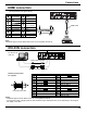
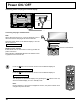
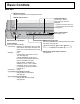
VIDEO and COMPONENT / RGB IN connection
AUDIO
OUT
R
L
VIDEO
OUT
AUDIO
OUT
R
L
, Y , P B , P R
OUT
P
R
P B
Y
Notes:
• Change the “COMPONENT/RGB-IN select” setting in the “SETUP”
menu to “COMPONENT” (when COMPONENT signal connection)
or “RGB” (when RGB signal connection). (see page 51)
• Signals input to COMPONENT/RGB IN terminals correspond to
SYNC ON G or SYNC ON Y.
RCA-BNC
Adapter plug
RCA-BNC
Adapter plug
DVD Player
VCR
Computer RGB Camcorder
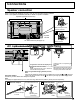
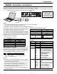
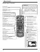
Connections
Video equipment connection
SLOT: Terminal board (optional
accessories) insert slot
(see page 6)
Note:
The right side slot is for terminal board
with 2-slot width. The terminal board
with 1-slot width does not function when
installed in the right side slot.
AV IN (HDMI):
HDMI Input Terminal
(see page 13)
Connect to video equipment
such as VCR or DVD player.
WIRELESS
MODULE, LAN:
Refer to “Operating
Instructions, Network
Operations”.
DVI-D IN: DVI-D Input Terminal (see page 13)
PC IN: PC Input Terminal Connect to video terminal of
PC or equipment with Y, PB(CB) and PR(CR) output.
(see page 14)
SERIAL:
Control the Plasma Display
by connecting to PC.
(see page 15)
3D IR TRANSMITTER:
Connect the 3D IR
TRANSMITTER (optional
accessory).
Terminals are on the bottom side of the Plasma Display.
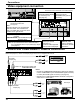
Note:
Additional equipment, cables and adapter plugs shown are not supplied with this set.
AUDIO L-R: Shared with VIDEO and
COMPONENT/RGB IN
AV IN (VIDEO): Composite Video Input Terminal
(see below)
COMPONENT/RGB IN: Component/RGB Video Input
Terminal (see below)