Panasonic 2007 L.C.D.
Today’s seminar’s contents are 1. Review and Chassis Structure 2. Signal Circuit 3. Trouble Shooting 4. Power Supply circuit 5. Protection circuit 6.
1.
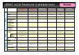
Picture 2007 LCD Feature Comparison LXD/LX700 Series LXD/LX70 Series LMD70 Series LM70 Series LXD/LED7 Series LE7 Series Size 32 32/26 32/26/20 32/26 32/26 32/26 Panel IPS α IPS α IPS VA IPS VA Motion Picture Pro Y Y - - - - Intelligent Scene Controller Y Y Y - Y - Advanced 3D Colour Management Y Y Y - Y - Sub-Pixel Controller Y Y Y - Y - Advanced Smart Sound Speaker (Side) Bottom Speaker Bottom Speaker Bottom Speaker Bottom Speaker Bottom Speaker Bambo
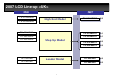
2007 LCD Line-up 2006 TX-32LXD600 TX-32LXD600 2007 TX-32LXD700 TX-32LXD700 S-3 TX-32LXD60 TX-32LXD60 TX-32LXD70 TX-32LXD70 S-2 TX-26LXD60 TX-26LXD60 TX-26LXD70 TX-26LXD70 S-2 TX-32LMD70 TX-32LMD70 S-3 TX-26LMD70 TX-26LMD70 S-3 TX-32LXD7 TX-32LXD7 S-3 TX-26LXD7 TX-26LXD7 S-3 TX-26LXD600 TX-26LXD600 TX-23LXD60 TX-23LXD60 TX-32LXD6 TX-32LXD6 TX-26LXD6 TX-26LXD6 High High End End Model Model Step Step Up Up Model Model Leader Leader Model Model 5
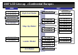
2007 LCD Line-up 2007 2006 TX-32LX600F TX-32LX600F TX-26LX600F TX-26LX600F IDTV Model High High End End Model Model TX-32LX700F TX-32LX700F S-5 TX-32LX70F TX-32LX70F S-2 TX-26LX70F TX-26LX70F S-2 TX-32LXD700F TX-32LXD700F S-5 TX-32LX60F TX-32LX60F TX-26LX60F TX-26LX60F TX-23LX60F TX-23LX60F Step Step Up Up Model Model TX-32LXD70F TX-32LXD70F S-2 TX-26LXD70F TX-26LXD70F S-2 TX-32LXD71F TX-32LXD71F S-2 TX-26LXD71F TX-26LXD71F S-2 TX-32LM70F TX-32LM70F S-2 TX-26LM70F TX-26L
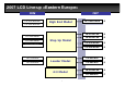
2007 LCD Line-up 2006 TX-32LX600P TX-32LX600P TX-26LX600P TX-26LX600P 2007 High High End End Model Model TX-32LX60P TX-32LX60P TX-26LX60P TX-26LX60P Step Step Up Up Model Model TX-23LX60P TX-23LX60P TX-32LX6P TX-32LX6P TX-26LX6P TX-26LX6P Leader Leader Model Model 4:3 4:3 Model Model 7 TX-32LX700P TX-32LX700P S-5 TX-32LX70P TX-32LX70P S-2 TX-26LX70P TX-26LX70P S-2 TX-32LM70P TX-32LM70P S-2 TX-26LM70P TX-26LM70P S-2 TX-32LE7P TX-32LE7P S-3 TX-26LE7P TX-26LE7P S-3 TX-20L
New LCD V-REAL Panel IPS Alpha LCD Panel The IPS Alpha LCD panel offers a wider viewing angle than an ordinary VA-system LCD so colours in the displayed picture appear beautiful even when viewed from an angle. The LX700's IPS Alpha LCD panel provides a viewing angle of 178 degrees.
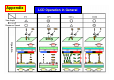
Appendix Appendix View Angle Response Speed LCD Operation in General Operation
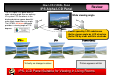
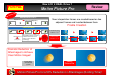
New LCD V-REAL Driver 1 FOR PAL New Motion Picture Pro Review gy olo n h Tec Conventional LCD TV 50 frames/sec New interpolation frames are created based on two adjacent frames and inserted between them.
New LCD V-REAL Driver 2 Intelligent Scene Controller Review Light intensity of the backlight remains consistent regardless of scenes. Backlight Ordinary LCD TV Consistent light intensity White cast over blacks 's Advantages ogy nol h c Te (1) Backlight turned down in intensity for dark scenes Sceneadaptive backligh t control gy olo n h Tec Reduction of light intensity 0.14 times max.
VIERA Link Now you can enjoy the beautiful sounds and pictures of highquality AV equipment without all the messy, unsightly cables. With HDMI, a single cable* carries the video, audio and control signals between two digital components. By using VIERA Link (= HDAVI-Control) compatible components, you can turn on the power for your entire home theater with a single remote control button, and begin playback immediately. Operating your DIGA recorder is easier and smarter too.
SD Card Slot (For Displaying Photos and Moving Picture Taken by a Digital Still Camera or HD Video Camera) Shooting Review Viewing [Photos and Moving Picture] Insert the SD Memory Card into VIERA and view the photos and moving picture on the large screen. LUMIX's* LUMIX's* HDTV HDTV mode mode displays full-screen displays full-screen photos photos and and moving moving picture picture on on the the wide-screen wide-screen TV. TV.
1-(1) Chassis structure Board layout 32LXD700/LX700 32LXD700/LX700 32LXD600/LX600 32LXD600/LX600 KEY Control K P AP DG (HDMI) XV SP AP SP SP H SP GS H G G P V SP SP K 32/26LXD600 only Differences from LXD600/LX600: 1. XV board is combined to DG board. 2. GH board for front HDMI is added. 3. KEY Control is added on the top. 4. Position of DG, P, GS, K, G and AP board are changed.
1-(2) Chassis structure Board layout 32LXD70/LX70 32LXD70/LX70 32LXD60/LX60 32LXD60/LX60 KEY Control K KEY Control K AP AP H A (HDMI) B H XV P P DG G (HDMI) SP SP SP V LXD60 only Differences from LXD60/LX60: 1. XV board is combined to DG board. 2. The function of A board is separated to DG and H boards. 3. AV3 terminal is changed from H board to G board.
1-(3) Chassis structure 32LXD600/LX600 32LXD600/LX600 32LXD700/LX700 32LXD700/LX700 DG DG XV DVB Tuner Function GC5 DVB Tuner LVDS TX Peaks Lite HQ1L LVDS TX GC3FS Peaks Lite2 HDMI x2 (CEC) HDMI x2 (CEC) LXD600 only LXD700 only Differences from LXD600/LX600: 1. The function of XV board is combined to DG board. 2. Peaks Lite on XV board and GC5 and GC3FS on DG board are changed to Peaks Lite2 on DG board. 3. HQ1L on DG board is newly introduced.
1-(4) Chassis structure 32LXD60/LX60 32LXD60/LX60 XV DVB Tuner A 32LXD70/LX70 32LXD70/LX70 Audio Processor DG H RGB SWITCH Audio SWITCH AUDIO PROCESSOR VIDEO SWITCH DVB Tuner HQ1L LVDS TX AD Converter AUDIO SWITCH VCTP LVDS TX Function VIDEO SWITCH HDMI x2 (CEC) LXD60 only Peaks Lite2 HDMI x2 (CEC) LXD70 only Differences from LX60/LXD60: 1. The function of A board is separated to DG board and H board. 2. For LXD60 series, XV board is combined to DG board. 3.
1-(5) Chassis structure Board Function 32LXD700/LX700 32/26LXD70/LX70 P Main Input, Power Supply Yes Yes AP Power Supply Regulator Yes Yes DG Peaks Lite2, HDMI, IDTV Processor (*1) Yes (*1) Yes (*1) H AV Connector, Tuner, AV Switch Yes Yes K Main Switch Yes Yes G Side AV Terminal Yes Yes Control Panel Assy Control Button Yes Yes V LED IR, Remote Receiver Yes Yes GS SD Card slot Yes - GH HDMI (Front) Yes - None serviceable (*2) * 1 LXD700 and LXD70 have the Digita
Today’s seminar’s contents are 1. Review and Chassis Structure 2. Signal Circuit 3. Trouble Shooting 4. Power Supply circuit 5. Protection circuit 6.
2.
2.
2-1.
2-1.(2) Signal circuit Over view Input Source Panel Drive Signal Processor GH K V Digital Tuner Analogue Tuner Only LXD H HDMI LCD panel DG Specification is defined by each panel supplier AV input Comp.
2-2.(1) Video Signal Flow DG IC4503 HDMI1 GH HDMI SW DIG.
2-2.(2) Video Signal Flow Analogue Tuner DG IC4503 HDMI1 GH HDMI SW DIG.
2-2.(3) Video Signal Flow Analogue Input DG IC4503 HDMI1 GH HDMI SW DIG.
2-2.(4) Video Signal Flow Digital Tuner DG IC4503 HDMI1 GH HDMI SW DIG.
2-2.(5) Video Signal Flow HDMI Input DG IC4503 HDMI1 GH HDMI SW DIG.
2-2.(6) Video Signal Flow SD Card DG IC4503 HDMI1 GH HDMI SW DIG.
2-3.(1) Audio Signal Flow Analogue Tuner GH IC4503 DG HDMI1 HDMI3 HDMI SW Analog Digital HDMI2 DIG.
2-3.(2) Audio Signal Flow Analogue Input GH IC4503 DG HDMI1 HDMI3 HDMI SW Analog Digital HDMI2 DIG.
2-3.(3) Audio Signal Flow Digital Tuner GH IC4503 DG HDMI1 HDMI3 HDMI SW Analog Digital HDMI2 DIG.
2-3.(4) Audio Signal Flow HDMI DG GH IC4503 HDMI1 HDMI3 HDMI SW Analog Digital HDMI2 DIG.
Today’s seminar’s contents are 1. Review and Chassis Structure 2. Signal Circuit 3. Trouble Shooting 4. Power Supply circuit 5. Protection circuit 6.
3.
3.
3.
3-1.(1) Picture trouble for some part of screen Input Source Signal Processor Panel GH V K HDMI Digital Tuner Analogue Tuner LCD Panel DG AV input Comp.
3-1.
3-1.
3-1.(4) Picture trouble for some part of screen Upper half or Lower half trouble No Picture, Picture noise, Full Horizontal line, etc.
3-1.(5) Picture trouble for some part of screen Left half or Right half trouble No Picture, Picture noise, Full Horizontal line, etc.
3-1.
3-1.
3-1.
3-1.
3-2.
3-2.
3-2.(3) Picture trouble for all over screen O.S.D.
3-2.
3-3.
Today’s seminar’s contents are 1. Review and Chassis Structure 2. Signal Circuit 3. Trouble Shooting 4. Power Supply circuit 5. Protection circuit 6.
4.
4.
4-1.(1) Power circuit Overview AP board AC Plug STB 5V Relay DTV 9V 24V Regulator HQ 3.
4-1.(2) Power circuit Overview Power SW AC Plug in STB 5V P K Standby Trans AP H DG STB 5V Relay ON Panel STB ON TV main ON Relay Regulators SW SUB ON Micom Micom Sound 15V Sub 5V DTV 9V HQ3.
4-1.(3) Power circuit Overview AC Plug Basic Process Power SW STB 5V P K Standby Trans AP H DG STB 5V Relay ON Panel STB ON TV main ON Relay Regulators SW SUB ON Micom Micom Sound 15V Sub 5V DTV 9V HQ3.
4-1.(4) Power circuit Overview AC Plug Basic Process Power SW STB 5V P K Standby Trans AP H DG STB 5V SUB ON Relay ON Panel STB ON TV main ON Relay Regulators SW Micom Micom Sound 15V Sub 5V DTV 9V HQ3.
4-1.(5) Power circuit Overview AC Plug Basic Process Power SW STB 5V P K Standby Trans AP H DG STB 5V SUB ON Relay ON Panel STB ON TV main ON Relay Regulators SW Micom Micom Sound 15V Sub 5V DTV 9V HQ3.
4-1.(6) Power circuit Overview Basic Process AC Plug Power SW STB 5V P K Standby Trans AP H DG STB 5V SUB ON Relay ON Panel STB ON TV main ON Relay Regulators SW Micom Micom Sound 15V Sub 5V DTV 9V HQ3.
4-1.(7) Power circuit Overview AC Plug Basic Process Power SW STB 5V P K Standby Trans AP H DG STB 5V SUB ON Relay ON Panel STB ON TV main ON Relay Regulators SW Micom Micom Sound 15V Sub 5V DTV 9V HQ3.
4-1.(8) Power circuit Overview AC Plug Basic Process Power SW STB 5V P K Standby Trans AP H DG STB 5V SUB ON Relay ON Panel STB ON Relay Micom Micom TV main ON Regulators SW Sound 15V Sub 5V DTV 9V HQ3.
4-1.(9) Power circuit Overview AC Plug Basic Process Power SW STB 5V P K Standby Trans AP H DG STB 5V SUB ON Relay ON Panel STB ON Relay Micom Micom TV main ON Regulators SW Sound 15V Sub 5V DTV 9V HQ3.
4-1.(10) Power circuit Overview AC Plug Basic Process Power SW STB 5V P K Standby Trans AP H DG STB 5V SUB ON Relay ON Panel STB ON Relay Micom Micom TV main ON Regulators SW Sound 15V Sub 5V DTV 9V HQ3.
4-1.(11) Power circuit Overview Basic Process Power SW AC Plug STB 5V P K Standby Trans AP H DG STB 5V SUB ON Relay ON Panel STB ON Relay Micom Micom TV main ON Regulators SW Sound 15V Sub 5V DTV 9V HQ3.
4-2.
4-2.
4-2.
4-2.
4-2.
4-2.
4-2.(7) Power Supply Sequence PP 32LXD700series DG former> FUSE IC1100 Panel stand by ON 105 5V T801 TV Main ON 29 STB 5V Sense 1 Relay> RL802 AP SUB ON 46 MAIN 5V SENSE 27 STB 5V SENSE 29 DTV 9V SENSE 30 SUB 5V SENSE 34 IC7301 IC7401 Sub 5V 24V IC7501 Panel IC7601 IC7701 Regulators 72 DTV 9V HQ3.
4-2.(8) Power Supply Sequence 32LXD700series PP DG former> FUSE IC1100 Panel stand by ON 105 5V T801 TV Main ON 29 STB 5V Sense 1 Relay> RL802 AP SUB ON MAIN 5V SENSE 27 STB 5V SENSE 29 DTV 9V SENSE 30 SUB 5V SENSE 34 IC7301 IC7401 IC7501 Panel IC7601 IC7701 Regulators 73 46 Sub 5V DTV 9V HQ3.
4-2.(9) Power Supply Sequence PP 32LXD700series DG former> FUSE IC1100 Panel stand by ON 105 5V T801 29 STB 5V Sense 1 Relay> RL802 Panel AP SUB ON TV Main ON 46 MAIN 5V SENSE 27 STB 5V SENSE 29 DTV 9V SENSE 30 SUB 5V SENSE 34 IC7301 Sound 15V IC7401 Sub 5V IC7501 DTV 9V Main 9V IC7601 HQ3.
4-2.(10) Power Supply Sequence PP 32LXD700series DG former> FUSE IC1100 5V T801 Panel stand by ON 105 TV Main ON 46 29 STB 5V Sense 1 Relay> RL802 Panel AP SUB ON MAIN 5V SENSE 27 STB 5V SENSE 29 DTV 9V SENSE 30 SUB 5V SENSE 34 IC7301 IC7401 Sound 15V IC7501 DTV 9V Main 9V IC7601 HQ3.
4-2.(11) Power Supply Sequence PP 32LXD700series DG former> FUSE IC1100 5V T801 Panel stand by ON 105 TV Main ON 46 29 STB 5V Sense 1 Relay> RL802 Panel AP SUB ON MAIN 5V SENSE 27 STB 5V SENSE 29 DTV 9V SENSE 30 SUB 5V SENSE 34 IC7301 IC7401 Sound 15V IC7501 DTV 9V Main 9V IC7601 HQ3.
4-2.(12) Power Supply Sequence PP 32LXD700series DG former> FUSE IC1100 5V T801 29 STB 5V Sense 1 Relay> AP RL802 SUB ON Panel stand by ON 105 TV Main ON 46 MAIN 5V SENSE 27 STB 5V SENSE 29 DTV 9V SENSE 30 SUB 5V SENSE 34 IC7301 Sub 5V IC7401 Sound 15V IC7501 DTV 9V Main 9V IC7601 HQ3.
Ref: AP Board Regulator Circuit(1) 24V 24V IC7301 15V AP SOUND 15V IC7401 5V SUB 5V DTV 9V Q7551 FET IC7501 9V MAIN 9V IC7601 HQ3.3V 3.
Ref: AP Board Regulator Circuit(2) 24V 24V IC7301 15V AP SOUND 15V IC7401 5V SUB 5V DTV 9V Q7551 FET IC7501 9V MAIN 9V IC7601 HQ3.3V 3.
Ref: AP Board Regulator Circuit(3) 24V 24V IC7301 15V AP SOUND 15V IC7401 5V SUB 5V ON DTV 9V Q7551 FET IC7501 9V MAIN 9V ON IC7601 HQ3.3V 3.
Ref: AP Board Regulator Circuit(4) 24V 24V IC7301 15V AP SOUND 15V IC7401 5V SUB 5V ON DTV 9V Q7551 FET IC7501 9V MAIN 9V ON IC7601 HQ3.3V 3.
Ref: AP Board Regulator Circuit(5) 24V 24V IC7301 15V ON AP SOUND 15V IC7401 5V SUB 5V ON DTV 9V Q7551 FET IC7501 9V ON MAIN 9V ON IC7601 HQ3.3V 3.
Ref: AP Board Regulator Circuit(6) 24V 24V IC7301 15V ON AP SOUND 15V IC7401 5V SUB 5V ON DTV 9V Q7551 FET IC7501 9V ON MAIN 9V ON IC7601 HQ3.3V 3.
Ref: AP Board Regulator Circuit(7) 24V 24V IC7301 15V ON AP SOUND 15V IC7401 5V SUB 5V ON DTV 9V Q7551 FET IC7501 9V ON MAIN 9V ON IC7601 HQ3.3V 3.
Ref: AP Board Regulator Circuit(8) 24V 24V IC7301 15V ON AP SOUND 15V IC7401 5V SUB 5V ON DTV 9V Q7551 FET IC7501 9V MAIN 9V ON ON IC7601 HQ3.3V 3.
4-3.(1) Power Distribution 24V AP 24V IC7301 15V SOUND 15V ① SUB 5V ② IC7401 5V ③ DTV 9V IC7501 Q7551 FET 9V MAIN 9V ④ ON IC7601 3.3/9V HQ3.
4-3.
4-3.(3) Power Distribution DTV 9V・Main 9V AP H IC3001 IC8001 Peaks Lite2 DG Video SW IC4002 Regulator IC5660 Reset IC5600 DC/DC decoder IC8004 Clock gain IC3002 Audio Switch ③ AP3 H3 IC2011 17 17 Audio Amp 18 IC2690 Q2639 BT30V Supply IC7501 DTV 9V 18 IC 8301 IC8601 COFDM DEM EPROM SUB3.3V IC5660 DTV9V→SUB 3.
4-3.(4) Power Distribution HQ3.3V AP H DG IC4207 LVDS ⑤ IC7601 HQ 3.3V AP4 H4A H2 DG2 16 16 1 1 17 17 2 2 MHQDLV3.3V IC4203 IC4205 Regulator IC4206 MHQDDR2.5V MHQLV3.3V MHQPL1.2V MHQPL3.3V MHQDDR1.
4-3.
4-3.(6) Power Distribution STB5V K AP H DG SW K8 P6 3 3 ⑦ AP4 H4A H2 DG2 3 3 23 23 STB 5V IC5670 IC1100 GENX4 IC1101 EPROM 91 STB 3.
Today’s seminar’s contents are 1. Review and Chassis Structure 2. Signal Circuit 3. Trouble Shooting 4. Power Supply circuit 5. Protection circuit 6.
5.
5.(1) Protection Circuit Once 4.0sec (interval) Light No Light LED Blinking times 1 No FAN 2 Contents INVERTER_SOS Check Point LCD panel, DG Board FAN SOS Board 3 REG. voltage abnormality H, AP, DG Board (BT30V,SOUND15V,PANEL12V,HQ3.3V Short) 4 DTV9V abnormality AP, H, DG Board (BT30V,SOUND15V,PANEL12V,HQ3.3V O.V.P.) 5 SUB5V abnormality AP, H, DG Board 6 MAIN9V abnormality AP, H, DG Board 7 MAIN5V abnormality DG Board 8 MAIN3.
5.(2) Protection Circuit Power LED Status No Light Defective Board P, DG Board Note : How to stop power supply completely is disconnecting AC cord, not turning OFF the power SW.
5.(3) LED 1 time blink 1 Contents Defective Board Inverter SOS LCD PANEL, DG Board Power SW ON. 12V output at DG27’s 1pin before Shutdown ? No 2 AP Board Yes Power SW ON. INV_ON output at DG27’s 2pin before Shutdown ? Yes 3 No DG Board Power SW ON. ADIM output at DG27’s 3pin before Shutdown ? Yes P T801 STB Trans No 4 DG Board Power SW ON.
5.(4) LED 3 times blink Contents Defective Board H, AP, DG Board DOWN :BT 30V, SOUND 15V, PANEL 12V, HQ 3.3V 1 Power SW ON. 24V output at P9’s 5-8 pin before shutdown ? No LCD Panel Yes 2 Disconnect AP3. No AP3’s 2,3,17,18 pin Short with GND ? 3 No Connect AP3. AP3’s 2,3,17,18 pin Short with GND ? Yes AP Board P P11 2 1 T801 STB Trans AP 5Vs 5Vs Line Filter RL802 Relay AP5 1-3 9 P5 1-3 9 1 Q802 4 Yes H Board IC7401 SUB 5V 5V IC7301 SOUND 15V 15V IC7501 DTV 9V 9V IC7601 HQ3.3V 3.
5.(5) LED 4 times blink Contents Defective Board Case1) DTV 9V down AP, H, DG Board Case2) Over :SOUND 15V, SUB5V, DTV9V, PANEL 12V, HQ 3.3V, 24V No (Over 24V) 1 Disconnect AP3. AP3’s 17,18 pin Short with GND ? No 2 Disconnect DG2. H2’s 8 pin Short with GND ? T801 STB Trans 5Vs 5Vs Line Filter 4 RL802 Relay P5 1-3 9 Q802 P9 5-8 AP AP5 1-3 3 15V 5V 9V 3.
5.(6) LED 5 times blink Contents Defective Board MAIN 9V AP, H, DG Board 1 Disconnect AP3. AP3’s 23 pin Short with GND ? No 2 Disconnect DG2.
5.(7) LED 6 times blink Contents Defective Board SUB 5V AP, H, DG Board 1 Disconnect AP3. AP3’s 21,22 pin Short with GND ? No 2 Disconnect DG2.
5.(8) LED 7 times blink Contents Defective Board MAIN 5V P T801 STB Trans DG Board The defective board is DG board only.
5.(9) LED 8 times blink Contents Defective Board MAIN 3.3V P T801 STB Trans DG Board 5Vs The defective board is DG board only. AP DG H IC8001,… 5Vs P11 2 1 Line Filter IC7501 Q7551 9V RL802 Relay P5 AP5 1-3 1-3 9 9 24V H2 DG2 IC5660 17-18 8-9 8-9 3.3V AP4 H4A DG6 8 8 H6 49 AP3 H3A 17-18 DTV9V Q5691 SUB Q5693 3.3V IC1100 MAIN 3.3V L MCU 67 MAIN3.
5.(10) LED 9 times blink Contents Defective Board 1 H, AP Board SOUND 15V SOS Power SW ON.
5.(11) LED 10 times blink Contents Defective Board HQ1L Communication(*) Error The defective board is DG board only. DG Board (*) HQ1L(IC4200)-Peakslite2(IC8001) Communication P H AP T801 STB Trans IC7401 5Vs 5V IC7501 5Vs P11 2 1 9V Line Filter IC7601 P5 RL802 Relay 1-3 9 AP5 1-3 9 3.3V SUB5V DG AP3 H3A 21 22 21 22 H2 12 13 14 17 18 17 18 8 9 AP4 H4A 16 17 16 17 1 2 DTV9V HQ3.3V 24V H6 8 8 49 DG2 IC4204,IC4208 12 SUB5V 3.3V 13 14 IC4202 SUB9V 8 1.
3-3.
Actual market trouble(1) 4 times LED blinking No picture Service manual (Usually) DTV9V abnormality (Front view) H AP, H, DG Board defect (BT30V,SOUND15V,PANEL12V,HQ3.3V O.V.P.
Actual market trouble(2) Strange sound Strange sound from back side or speaker ② ① ① Back side Inverter trouble Especially early morning. Panasonic ② Speaker 1)IC2106 defect.
Actual market trouble(3) Instable Picture Picture trouble later Normal picture No Picture After a while Normal sound Normal Sound Result IC4207, LVDS processor on DG board defect 108
Actual market trouble(4) Unstable condition Not always but sometime trouble Normal picture After a while No Picture Dark picture Freeze picture Normal picture After a while Power off Automatically Power ON Power on Automatically After a while After a while Result DG board defect 109