
Installation Manual


44
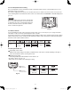
5-9. Electrical Wiring
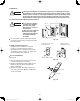
5-10-1. How to use the test run setting (U1, T1 Types)
(1) Set DIP switch [DS] No. 1 on the wireless receiver
unit PCB from OFF to the ON position.
(2) Press the ON/OFF operation button on the
wireless remote controller.
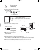
(3) Make a test run using the air conditioner in
COOL or HEAT mode.
(4) During the test run, each of the 3 indicator lamps
on the indoor unit fl ash.
(5) During the test run, the air conditioner runs
continuously and the thermostat does not control
the system.
(6) After the test run, be sure to reset DIP switch No. 1
back to the OFF position and check that no indicator
lamps are blinking.
(This receiver includes a 60-minute automatic OFF
timer function in order to prevent continuous test run.)
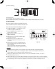
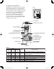
Fig. 5-10
WHT
BLK
1
2
W1 (4.3 ft.)
WL
Indoor PCB Operating controller
Signal receiving unit
Indicator section
W2
(0.7 ft.)
W3
(4.3 ft.)
CN1
CN2
Relay connector
CN1
BLU
YEL
PNK
RED
GRY
BLK
BLU
YEL
PNK
RED
GRY
BLK
NOTE
In case of 4-way Cassette type, test run operation is not possible without the ceiling panel installation.
To protect the air conditioner from overloading, the outdoor unit will not start running for 3 minutes after
power is applied or the air conditioner is turned off and then back on.
When the air conditioner fails to start the test run, 1 or more of the 3 alarm indicator lamps on the indoor
unit will flash (See next section).
When the DIP switch is set to “TEST – ON,” temperature control from the wireless remote controller is disabled.
Do not use this setting at any time other than for the test run. Doing so will place an excessive load on the system.
To avoid placing an excessive load on the equipment, use this function only when conducting the test run.
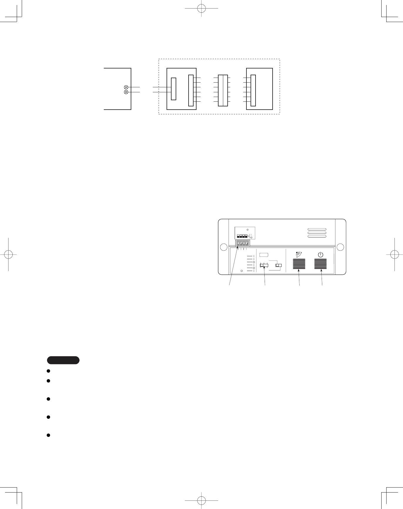
Fig. 5-11
1
1
ADR
1.TEST RUN
2.PCB CHK.
3.RCU: MAIN
RCU: SUB
4.NORMAL
ALL •
DIP switch
No. 1
Address
switch
ON/OFF
operation
button
All OFF( ) for
initial settings.
234
2 3
456
Flap
button
Connection method
(1) Connect W1 to the indoor PCB WL connector.
(2) Connect W3 from the indicator section with W2 from the operating controller using the relay connector.
5-10. Test Run Switch
The test run switch is located in the operating control unit.
See the Installation Instractions attached to the outdoor unit.
Panasonic_PAC-i_IndoorUnit_US-le44 44Panasonic_PAC-i_IndoorUnit_US-le44 44 2011/11/02 15:17:342011/11/02 15:17:34