Confidential DECT Microphone System Receiver Board Module for Specifications Audio Enhancement Approval Panasonic. Approval Ver. 1.
Confidential ■ INDEX Ver. 1.0 ................................................................................................................. i 1. GENERAL ........................................................................................................ 4 2. FEATURES ...................................................................................................... 4 3. SPECIFICATIONS ............................................................................................ 4 3.1.
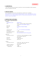
Confidential No. 1 Ver. Date 1.0 Change Time Revision Draft The blue sentences is the changing points from K-SRC14 (Wireless Receiver).
Confidential 1.GENERAL ・ These specifications describe the preliminary specifications of “Receiver Board Module for DECT Microphone System” for Audio Enhancement (AE). 2.FEATURES ・Receiver Board Module has same features and outside interface as DECT Receiver (K-SRC14).
Confidential OUTPUT (Amplifier interface) Connectors Adapted Load Impedance Nominal Output Level Mic output 1,2 Mix output Residual Noise : : : : : : RJ-45 (Type for LAN), connect to Amplifier 10kΩ or more -5dBV Balanced 0dBV Balanced -60dBV or less GENERL SPECIFICATIONS for AUDIO Cross talk : Dynamic Range : : : Signal to noise ratio (S/N) Frequency Response Total Harmonic Distortion Attenuator Mixing output attenuator -45dB or more @1kHz 80dB or more (Line In to Mix output Balanced) 80dB or more (L
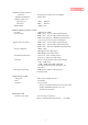
Confidential OTHER FUNTIONS Teacher’s over ride : Paging mute : Mic mixing : CONTROL TERMINAL The number of connectors This function will work when voice come into input from Mic CH1 or CH2. Then Mix-output level will be set to fixed attenuate level. Available On/Off control by Dip switch Attenuation = 12dB or more When Paging mute terminal is activated, this function will be work. At this time,Mic output channel 1 and 2,Mix-output level set to Mute Level.
Confidential INTERFACE CONNECTOR Amplifier interface Connector Recommended Cable Pin assignment DIP SWITCHES Teacher’s Over Ride Response Tone Response Tone Level Microphone Mix setting Feedback Blocker Volume Control Bypass (Remote volume) Mixing output attenuator RF Tx power setting Channel 3 VOL Line/Mic Alert ON/OFF Not use : : : RJ-45 (Type for LAN) , connect to Amplifier LAN Cable (CAT5) 1:Mic output 1 Hot 5: GND 2:Mic output 1 Cold 6:Mix output Cold 3:Mix output Hot 7: Mic output 2 Hot 4:Power
Confidential RF COMMUNICATION Antenna Specified Output Power : The number of Antenna: 2 Antenna type: Dipole Frequency range: 1,920 – 1,930 MHz Antenna gain: 0dBi : [Mode 1] (NORMAL) 0dBm (to Microphone) [Mode 2] (Hi POWER) 5dBm (to Microphone) Coverage : [Mode 1] (NORMAL) 20m [Mode 2] (Hi POWER) 30m Diversity Support : Space Diversity ( Except Broadcast) No Slot Diversity 3.2.Accessory Unattached: Operating Instructions Warranty Card : : None.
Confidential 4.SAFETY REQUEST In order to comply with the Panasonic Safety Regulations, take one of the following action on the AE product side.
5.
6.
FCC Caution Label Name plate label LINK Button Mic status indicator for CH1 Mic status indicator for CH2 LINK indicator Power indicator -12-
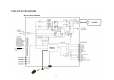
7.CONTROL TERMINAL SPECIFICATIONS 7.1.Electrical specifications a. E1,E2 terminal ・Output circuit type is open collector. It has diode to prevent reverse connection. ・The terminal could drive until 20mA against the load equipment ・Maximum voltage rating is 30VDC Name I/O Electrical specifications Equivalent Schematic E1 E1 E1 E2 output Max control Voltage : 30V Max control current : 20mA E2 E2 b. E2 Ack terminal ・Input configuration is transistor. It has diode to prevent reverse current.
c. Page mute terminal ・Input configuration is transistor. It has diode to prevent reverse current ・Designed for external device which has dry contact like relay output. ・5VDC will always appear on the terminal. ・Short current is 2mA If the terminal will be shorted by external device. Name Page mute I/O input Electrical specifications Equivalent Schematic To CPU Terminal voltage:5V Short current:2mA d. LINK Button terminal ・Input configuration is transistor.
e. Alert Notification Button terminal ・Input configuration is transistor. It has diode to prevent reverse current ・Designed for external device which has dry contact like relay output. ・5VDC will always appear on the terminal. ・Short current is 2mA If the terminal will be shorted by external device.
8.PACKAGING ACKAGING SPECIFICATIONS 8.1.
9.FCC AND INDUSTRY CANADA REQUIREMENTS REGARDING THE END PRODUCT 9.1.List of applicable FCC and IC rules K-SRB20 (Receiver Board Module) complies with FCC part15 subpart D and Industry Canada RSS 213 Issue3. 9.2.
9.4.Requirement of regarding the end product and manual End product and literature provided to the end user must include the following wording: Wording Display location Contains Transmitter Module User manual and end product FCC ID:ACJ9TAK-SRB20 IC:216M-KSRB20 CAN ICES-3(A)/NMB-3(A) User manual and end product FCC Caution: Changes or modifications not expressly approved by the party responsible for compliance could void the user's authority to operate the equipment.
9.5.Notice 1. This module (K-SRB20) is not the Limited Module. 2. There is no trace antenna design in the end product.