Ultra-miniature Size Sealed Switches Terminal type Mounting hole 2.3 mm type Wire leads bottom type Mounting hole 2.
ABJ (BJ) Turquoise Switches COMBINATION OF OPERATING FORCE (OF) AND APPLICABLE CURRENT RANGE (Reference) 2A AgNi alloy contact 1A OF1.23N OF1.96N 100mA Au-clad contact 1mA 0 DC 5V AC 5V 15V 15V 30V 125V Note) OF: Value of pin plunger Note: The diagram above is intended as a reference. Please use the product within the rated voltage and current.
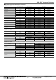
ABJ (BJ) Turquoise Switches ■ Wire leads bottom type: Mounting hole 2.3mm type 1) AgNi alloy contact Actuator Pin plunger Hinge lever Simulated roller lever Roller lever Operating Force OF Max. 1.23 N 1.96 N 0.39 N 0.64 N 0.39 N 0.64 N 0.39 N 0.
ABJ (BJ) Turquoise Switches ■ Wire leads side type: Fixed pin (left side pin) type 1) AgNi alloy contact Actuator Leaf lever Operating Force OF Max. Wire leads direction 1.27 N 1.27 N 1.76 N 1.76 N Right Left Right Left Operating Force OF Max. Wire leads direction 1.27 N 1.27 N 1.76 N 1.
ABJ (BJ) Turquoise Switches ■ Characteristics Item Specifications Leaf lever type: Min. 5×10⁵ (at 60 cpm) Wire leads side type: Min. 3×10⁵ (at 60 cpm) Other types: Min. 106 (at 60 cpm) Min. 3×10⁴ (at 20 cpm) (at rated load) Min. 105 (at 20 cpm) (at rated load) Min. 100 MΩ (at 500 V DC insulation resistance meter) 600 Vrms 1,500 Vrms 1,500 Vrms 10 to 55 Hz at single amplitude of 0.75 mm (Contact opening max. 1 msec.) Min. 294 m/s2 (Contact opening max. 1 msec.) Terminal type: Max. 50 mΩ Wire lead type: Max.
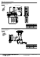
ABJ (BJ) Turquoise Switches DIMENSIONS (Unit: mm) General tolerance: ±0.25 The CAD data of the products with a CAD Data mark can be downloaded from: http://industrial.panasonic.com/ac/e/ ■ PC board terminal: Mounting hole 1.2 mm type Pin plunger External dimensions CAD Data PC board pattern 1.2±0.05 dia. 5.4±0.3 1.5 dia Pretravel 0.6Max. Operating Position 5.5±0.2 1.0 5.0±0.15 5.08±0.1 5.08±0.1 1.1±0.12 +0.12 2-0 1.5±0.1 5.50 dia. 1.5±0.12 1.6 0.9 5.08±0.15 t=0.4 6-C 0.3 6.5±0.1 1.
ABJ (BJ) Turquoise Switches ■ PC board terminal: Roller lever External dimensions CAD Data PC board pattern 2.2 Pretravel 3.0Max. 3.4±0.4 1.2±0.05 dia. 4.8 dia. 5.08±0.1 Operating Position 13.1±1.0 5.08±0.1 14.6±1.2 Pretravel PT, Max. Movement Differential MD, Max. Overtravel OT, Min. Distance from mounting hole Operating Position OP Distance from stand-off ■ Solder terminal Mounting hole 1.2 mm type External dimensions CAD Data 5.4±0.3 1.5 dia 7.8 4.6±0.3 Pretravel 0.
ABJ (BJ) Turquoise Switches ■ Wire leads bottom leaf lever type Mounting hole 3 mm type External dimensions CAD Data Pretravel 6 max. 13±0.1 9 R2.5 2.5 8.6±1 4.8±0.3 5 Free Position (19.0) Operating Position 16±2 +0.1 5 3.1–0.05 Totaltravel Position 11.5 3.3 9.25 7.5 6.5 3 COM +0 –0.15 dia. NO 4.4 NC R3.25 300±10 5±2 6 20.0±0.4 Pretravel PT, Max. Movement Differential MD, Max. Overtravel OT, Min.
ABJ (BJ) Turquoise Switches Wire leads left side type External dimensions CAD Data 9.53±0.1 6.7 C0.2 +0 5.0−0.2 2.6±0.05 R2.0 Free position (FP) 13.05 max. Operating position (OP) 10.7±0.7 Totaltravel position (TTP) (8.55) 6.0 5.0 2.2±0.05 dia. 9.53 7.6±1.0 6.9±0.3 3.45 2.6±0.05 Pretravel PT, Max. mm Movement Differential MD, Max. Overtravel OT, Min. Operating Distance from Position OP mounting hole 8.55 5±2 300 ±10 2.6mm 0.5mm 1.4mm 10.7±0.7mm 16.
ABJ (BJ) Turquoise Switches ■ Wire leads side leaf lever type Mounting hole 3mm type External dimensions CAD Data C0.30 +0.1 8.4−0.3 R2.0 +0.2 6.0−0.15 5.8±1.0 5.0 12.3 Free position (FP) 18.6 max. Operating position (OP) 16.25±0.7 Totaltravel position (TTP) (14.1) 1.85±0.3 +0 3.0−0.1 dia. +0.1 3.1−0 9.0 6.0 5±2 13.0±0.1 4.0 300 Pretravel PT, Max. Movement Differential MD, Max. Overtravel OT, Min. Operating Distance from Position OP mounting hole 3.3 ±10 19.6 2.6mm 0.5mm 1.4mm 16.25±0.
Notes for Turquoise Switches (BJ, BS, BV type) CAUTIONS FOR USE (Common for BJ, BS and BV types) ■ Fastening of the switch body 1) Fasten the switch body onto a smooth surface using the correct screw as shown in the chart below and tighten it with the prescribed torque. The switch case may deform depending on the type of screw (screw head diameter, etc.), the size of the washer, and the use or non-use of a washer. Therefore, please confirm the appropriate torque of actual conditions.
Notes for Turquoise Switches (BJ, BS, BV type) • Hydrogen sulfide exposure test Test conditions: Concentration: 3 ppm, Temperature: 40°C 104°F, Humidity: 75% RH Contact resistance Contact resistance • Dust protection test Test conditions: The talcum powder used shall be able to pass through a square- meshed sieve the nominal wire diameter of 7 μm. The amount of talcum powder to be used is 2 kg per cubic metre of the test chamber volume. The duration of the test is 8 hours.
Technical Terminology & Cautions for Use (Detection Switches) TECHNICAL TERMINOLOGY ■ Detection Switches A compact switch equipped with an enclosed micro-gap snapaction contact mechanism that makes a specified motion with a specified force to open/close a circuit, and an actuator outside the enclosure (hereinafter referred to as the switch) ■ Actuator A part of the switch that transmits the received external force to an internal spring mechanism to move the movable contact so that the switch can be opened a
Technical Terminology & Cautions for Use OPERATING CHARACTERISTIC ■ Definition of operating characteristic The main terminological illustrations and meanings which are used with snapaction switches are as follows. Classification RF OF PT TF Force TT FP OT Symbol Unit Varying display method Operating Force OF N Max. Release Force RF N Min. Totaltravel Force TF N Pretravel PT mm, degree Max. Overtravel OT mm, degree Min. Movement Differential MD mm, degree Max.
Technical Terminology & Cautions for Use TECHNICAL NOTES ON ELECTRICAL CHARACTERISTICS 1) The snap-action switch is designed for AC operations. While it has small contact gaps and no arc absorber, it may be used for low-capacity DC operations. Please refer to the rating of each products 2) For applications with very small switching voltage or current, choose the low-level load type (Au contact).
Technical Terminology & Cautions for Use MOUNTING STATE AND ENVIRONMENT ■ Checking the insulation distance After mounting and wiring, check the insulation distance between terminals and the ground. If the insulation distance is inadequate, mount insulating material between as required. ■ Fastening the snap-action switch body See the Section “CAUTIONS FOR USE” for the individual switch.
Technical Terminology & Cautions for Use ■ Usage, storage, and transport conditions (except turquoise switches) During usage, storage, or transportation, avoid locations subject to direct sunlight and maintain normal temperature, humidity, and pressure conditions. The allowable specifications for environments suitable for usage, storage, and transportation are given below. 1) Temperature: The allowable temperature range differs for each switch, so refer to the switch’s individual specifications.
Technical Terminology & Cautions for Use ■ Types of actuators Shape Pretravel (PT) Overtravel (OT) Operating Force (OF) Vibration Shock Pin plunger Small Small Large Outstanding Appropriate for linear short-stroke action. Pin plunger acts directly on snap action mechanism, enabling high-precision positioning. Amount of movement after operation is smallest among all of the actuators, however, so reliable stopper is required.