Advanced Hybrid System Getting Started Model KX-TEA308 KX-TEB308 Thank you for purchasing a Panasonic Advanced Hybrid System. Please read this manual carefully before using this product and save this manual for future use.
System Components System Components Table Model Main Unit Optional Service Cards Proprietary Equipment *1 Description KX-TEA308 Advanced Hybrid System: 3 Outside (CO) Lines, 8 Hybrid Extensions KX-TEB308 Advanced Hybrid System: 3 Outside (CO) Lines, 4 Hybrid and 4 SLT Extensions*1 KX-TE82460 2-Port Doorphone Card KX-TE82492 2-Channel Voice Message Card (for KX-TEA308 only) KX-TE82493 3-Port Caller ID Card KX-T30865 Doorphone KX-A227 Backup Battery Cable Taiwan: 4 PT Extensions For support
Important Safety Instructions When using your telephone equipment, basic safety precautions should always be followed to reduce the risk of fire, electric shock and injury to persons, including the following: 1. Read and understand all instructions. 2. Follow all warnings and instructions marked on the product. 3. Unplug the product from the wall outlet before cleaning. Do not use liquid cleaners or aerosol cleaners. Clean with a damp cloth. 4.
16. Keep the unit away from heating appliances and devices that generate electrical noise such as fluorescent lamps, motors and televisions. These noise sources can interfere with the performance of the PBX. 17. This unit should be kept free of dust, moisture, high temperature (more than 40 ˚C ) and vibration, and should not be exposed to direct sunlight. 18. If you are having problems making calls to outside destinations, follow this procedure to test the outside (CO) lines: 1.
Notice Regarding removing or replacing a battery in the circuit board, consult your dealer. For users in Finland, Norway and Sweden only • This unit may only be installed in a room or space with restricted access, and equipotential bonding must be applied. For information on earthing, refer to "2.7 Connecting Frame Earth". WARNING • • • • • • THIS UNIT MAY ONLY BE INSTALLED AND SERVICED BY QUALIFIED SERVICE PERSONNEL.
Precautions for Users in the United Kingdom FOR YOUR SAFETY, PLEASE READ THE FOLLOWING TEXT CAREFULLY. This appliance is supplied with a moulded three-pin mains plug for your safety and convenience. A 5 amp fuse is fitted in this plug. Should the fuse need to be replaced, please ensure that the replacement fuse has a rating of 5 amps and that it is approved by ASTA or BSI to BS1362. Check for the ASTA mark or the BSI mark on the body of the fuse.
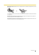
How to replace the fuse: Open the fuse compartment with a screwdriver and replace the fuse and fuse cover. The equipment must be connected to direct extension lines, and a payphone should not be connected as an extension. 999 and 112 can be dialled on the apparatus after accessing the Exchange line for the purpose of making outgoing calls to the BT emergency services. During dialling, this apparatus may tinkle the bells of other telephones using the same line.
Table of Contents 1 Before Installation .................................................................................. 9 1.1 1.2 2 Unpacking..........................................................................................................................9 System Connection Diagram .........................................................................................10 Installation............................................................................................. 11 2.1 2.2 2.
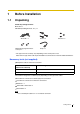
1 Before Installation 1.1 Unpacking Check the package contents. Main Unit × 1 CD-ROM (including manuals, etc.) × 1 *AC Cord × 1 Screw × 3 Mini Plug (for pager and music source) × 2 Strap × 1 Washer × 3 * The type of the AC cord may vary depending on the country/area of use. More than one type of AC cord may be included for countries/areas in Central and South America. Necessary tools (not supplied): Telephone cable for extension connection: Diameter of cable (ø 0.4 mm to ø 0.
1.2 System Connection Diagram Outside (CO) Line Remote PC External audio source (radio, CD player, etc.) Paging system (loudspeaker, amplifier and speaker, etc.) Batteries SLT PT Door Opener/ Doorbell/Door Chime Fax/Telephone Answering Machine Doorphone DSS Console PC Wireless Phone Printer • • 10 PC Voice Processing System Connect a display-equipped proprietary telephone (PT) to extension jack 01, as this extension is automatically designated as the manager extension.
2 Installation 2.1 Opening Covers 1. Pull the slide button to the right and, holding it, slide the cable cover upwards. Then turn the cable cover slightly to remove it. Slide Button Cable Cover 2.2 Connecting Outside (CO) Lines 1. Insert the modular plugs of the telephone line cords (2-conductor wiring) into the outside (CO) line jacks. 2. Connect the line cords to the terminal board or the modular jacks from the telephone company.
2.3 Connecting Extensions Extension jacks can be used for proprietary telephones (PTs), Direct Station Selection (DSS) Consoles, single line telephones (SLTs), and Voice Processing Systems. Notes • Connect a display-equipped proprietary telephone (PT) to extension jack 01, as this extension is automatically designated as the manager extension. For KX-TEB308, 4 extension jacks out of 8 can be used for SLTs*1 only. The following table shows the extension jack types.
2.4 Securing the Cables 1. Attach the included strap to either of the 2 rails depending on your preference. Rail Rail 2. Bind the cables as shown.
2.5 Closing Covers 1. Attach the rear hooks on the cable cover to the main unit, then swing the cable cover closed so that the front hooks fit in place. Cable Cover 2. Slide the cable cover down until it locks. Note For safety reasons, keep the front cover closed while the PBX is in operation.
2.6 Wall Mounting The PBX is designed for wall mounting only. The wall where the PBX is to be mounted must be able to support the weight of the PBX. When wall mounting the main unit, use either the included screws, or screws of the same size. 2.6.1 Mounting on a Wooden Wall The included screws may be used when mounting the main unit on a wooden wall. 1. Place the template (found on the last page of this manual) on the wall to mark the 3 screw positions. 120 mm Template 232 mm 2.
Notes • • • 2.6.2 Do not block the openings of the cabinet. Leave at least 20 cm of space above and 10 cm to the sides of the PBX for ventilation. Make sure that the wall behind the cabinet is flat and free of obstacles, so that the openings on the back of the cabinet will not be blocked. Be careful not to drop the cabinet. Mounting on a Concrete or Mortar Wall The included screws may be used when mounting the main unit on a concrete or mortar wall. Usersupplied anchor plugs are also necessary. 1.
4. Affix the PBX to the screw heads. Notes • • • 2.7 Do not block the openings of the cabinet. Leave at least 20 cm of space above and 10 cm to the sides of the PBX for ventilation. Make sure that the wall behind the cabinet is flat and free of obstacles, so that the openings on the back of the cabinet will not be blocked. Be careful not to drop the cabinet. Connecting Frame Earth IMPORTANT Connect the frame of the PBX to earth. 1. 2. 3. 4. Loosen the screw. Insert an earthing wire (user-supplied)*.
• • • 18 Be sure to comply with all applicable laws, regulations, and guidelines. Proper earthing is very important to protect the PBX from external noise and to reduce the risk of electrocution in the event of a lightning strike. The AC cable's earthing pin may not be enough to protect the PBX from external noise and lightning strikes. A permanent connection must be made between earth and the earth terminal of the main unit.
3 Starting the Advanced Hybrid System 3.1 Starting the Advanced Hybrid System This section explains the procedure for starting the PBX for the first time, with default values, or when you wish to re-initialise the PBX. 1. 2. 3. 4. Make sure that all outside (CO) lines you use are connected to the PBX. Set the Power Switch to the "OFF" position. Connect the AC cord to the PBX, then plug the AC cord into an AC outlet. Set the Power Switch to the "ON" position.
CAUTION • • Notes • • • 20 Getting Started The PBX is powered as long as the AC cord is plugged into an AC outlet, even if the Power Switch is set to the "OFF" position. The power supply cord is used as the main disconnect device. Ensure that the AC outlet is located/installed near the equipment and is easily accessible. If the outside (CO) lines you use are not connected to the PBX, outside (CO) line type can not be automatically detected. Use only the AC cord included with the PBX.
4 PC Programming 4.1 PC Programming PBX features and settings can be customised using a PC and the KX-TE308 Maintenance Console software. Customisation and maintenance can be done easily and efficiently using Windows-based PC programming software, with graphical icons to guide you. Programming can be performed both on-site, using a PC connected directly to the PBX, and off-site, by accessing the PBX via modem. This allows settings to be changed quickly to meet users' needs, locally or remotely.
5 PT Programming 5.1 Programming Instructions The PBX can be programmed by entering 3-digit programming numbers with a PT. In this manual, how to programme some features through PT is explained. Required Telephone PBX settings can be customised through system programming by using a proprietary telephone (PT) with a display, such as the KX-T7730. Connect the PT to the extension jack 01 to access system programming.
Fixed Button (KX-T7730/KX-T7735) Function SELECT FLASH CLEAR Entering System Programming Mode To enter system programming mode, the system password is required. # System Password for Administrator—for PT Programming Programming No. 1234 3 digits Note means default value throughout these programming instructions. 5.2 Programming Procedures Notes • means default value throughout these programming instructions. • • means to select "All" throughout these programming instructions.
The PT's dialling buttons can be used to enter characters when storing a name or message.
Table 3 (Cyrillic alphabet mode for RU [Russia]/UA [Ukraine] model) * This character is only available for the KX-T7735RU. [Example of Entering Characters] To enter "Ann": n A 2 Notes • 6 n (5 times) OR 6 (5 times) To toggle between "Alphabet mode" and "Numeral mode" or between "Alphabet mode", "Cyrillic alphabet mode (assignable only in Extension Name in Cyrillic [616] )", and "Numeral mode", press SELECT. • To move the cursor right, press . • To delete all characters, press CLEAR.
5.2.1 Basic Features Date & Time [000] 0 0 0 NEXT ➞ year ➞ (1…12) (Sun…Sat) Notes • • hour ➞ day (Jan.…Dec.) (00…99) SELECT ➞ SELECT ➞ minute (00…59) ➞ (1…31) SELECT STORE END (AM/PM) The clock starts immediately after the STORE button is pressed. The PBX supports years from 2004 to 2099. System Speed Dialling Number [001] NEXT or PREV To continue 0 0 1 NEXT speed dialling no. (00…99) phone no. STORE END Max.
2. To avoid unauthorised access and possible fraudulent dialling, maintain the secrecy of the password. 3. We strongly recommend that you change the default password value to something else for reasons of system security. It is best to use a password of 7 digits. 4. Please change the password periodically. 5. If a system password is forgotten, it can be found by loading a backup of the system data into a PC, and checking the password using the KX-TE308 Maintenance Console software.
System Speed Dialling Name [011] NEXT or PREV To continue 0 1 1 NEXT speed dialling no. (00…99) name* Max. 16 characters STORE END To continue SELECT Note * A name can be stored using a PT's dialling buttons. The displayed character varies depending on the number of times that the dialling button is pressed. It is possible to toggle between "Alphabet mode" and "Numeral mode" by pressing SELECT.
Extension Name [604] NEXT or PREV To continue 6 0 4 NEXT extension jack no. (01…08) extension name* STORE Max. 10 characters To continue END SELECT Note * An extension name can be stored using a PT's dialling buttons. The displayed character varies depending on the number of times that the dialling button is pressed. It is possible to toggle between "Alphabet mode" and "Numeral mode" by pressing SELECT.
5.2.2 Toll Restriction (TRS) Features Toll Restriction (TRS) can prohibit certain extension users from making unauthorised outside (CO) line calls. Every extension is assigned to one of 5 classes of service (COSs) for each time service mode (TRS-COS—Day/Night/Lunch [601-603]); COS 1 grants the highest level of authorisation, allowing all outside (CO) line calls to be made, and COS 5 grants the lowest level of authorisation.
TRS—COS 2-5 Denied Code [302-305] NEXT or PREV To continue 3 X NEXT (02…05) code no. phone no. STORE (01…20) Max. 11 digits (0…9, , #, x) To continue 02: for Class 2 03: for Class 3 04: for Class 4 05: for Class 5 END SELECT TRS—Exception Code [306] NEXT or PREV To continue 3 0 6 NEXT code no. phone no. STORE (01…80) Max.
Getting Started
Getting Started 33
Getting Started
120 mm Install a screw here. Install a screw here. TEMPLATE FOR WALL MOUNTING 1. Copy or print this template and place it on the wall. 2. Install the screws as marked. If you mount the main unit on a concrete or mortar wall, fit anchor plugs (not included) into the wall beforehand. 3. Hook the unit onto the screw heads. Install a screw here. 60 mm 232 mm Note Make sure to set the print size to correspond with the size of this page.
Electronic documentation for the KX-TEA308/KX-TEB308 can be found on the included CD-ROM. To view this documentation, simply insert the CD-ROM into your PC—your default web browser will launch automatically and open the appropriate file. To view the documentation manually, start by opening the file named "index.html" with your web browser. Notes • • A web browser and a PDF viewer are required to view the included documentation.