Ò NTSC Digital Video Camera Recorder Model AG- P Before operating this product, please read the instructions carefully and save this manual for future use.
IMPORTANT “Unauthorized recording of copyrighted television programs, video tapes and other materials may infringe the right of copyright owners and be contrary to copyright laws.” CAUTION RISK OF ELECTRIC SHOCK DO NOT OPEN CAUTION: TO REDUCE THE RISK OF ELECTRIC SHOCK, DO NOT REMOVE COVER (OR BACK). NO USER SERVICEABLE PARTS INSIDE. REFER TO SERVICING TO QUALIFIED SERVICE PERSONNEL.
Important Safeguards 1. Read Instructions — All the safety and operating instructions should be read before the unit is operated. 2. Retain Instructions — The safety and operating instructions should be retained for future reference. 3. Heed Warnings — All warnings on the unit and in the operating instructions should be adhered to. 4. Follow Instructions — All operating and maintenance instructions should be followed. 5. Cleaning — Unplug this video unit from the wall outlet before cleaning.
Important Safeguards 13. Outdoor Antenna Grounding — If an outside antenna or cable system is connected to the video unit, be sure the antenna or cable system is grounded so as to provide some protection against voltage surges and builtup static charges.
Contents Accessories . . . . . . . . . . . . . . . . . . . . . . . . . .6 Precautions for use . . . . . . . . . . . . . . . . . . . .7 Storage tips . . . . . . . . . . . . . . . . . . . . . . . . . . .9 Parts and their functions . . . . . . . . . . . . . . .10 Remote control unit . . . . . . . . . . . . . . . . . . .20 Charging the battery . . . . . . . . . . . . . . . . . .21 Mounting the battery . . . . . . . . . . . . . . . . . .22 Supplying power from the AC adapter . . . .22 Cassette tapes . . . . . .
Accessories OBattery (2) OEye cup (VMG1458) OMicrophone holder (VYC0870) OAC adapter (2) OScrews 6 mm in length (XSB4+6FZ) a2 12 mm in length (XSB4+12FZ) a2 OAC cable (K2CB2CB00006) OMicrophone holder adapter (VYC0890) OShoulder strap (VFC3891) ODC cable (VEK8722) OMini DV cassette tape (AY-DVM63MQ) OWireless remote control unit (VFA0402) OBattery for remote control unit (CR2025) 6 2: Refer to the “OPTIONAL ACCESSORIES” item (on page 70) for the model numbers of the battery and AC adapter.
Precautions for use Take care to prevent water from entering inside the camera recorder when using it in the rain or snow or at the seashore or in other similar environments. O Failure to heed this caution may cause the camera recorder and/or cassette to malfunction (possibly leading to irreparable damage). Keep the camera recorder away from equipment (such as TV sets and TV game machines) that generate magnetic fields.
Precautions for use Battery characteristics This camera recorder uses a rechargeable lithium-ion battery which produces electrical energy by means of an internal chemical reaction. This reaction tends to be easily affected by the ambient temperature and humidity, and the period during which the battery can be effectively used decreases as the temperature becomes very high or low. The battery charge will last for only 5 minutes if the battery is used in an environment where the temperature is extremely low.
Storage tips When storing the camera recorder, eject the cassette from the camera recorder and remove the battery. Store all components in a location where the humidity level is low and the temperature is relatively stable. Recommended temperature range: 59°F to 77°F (15°C to 25°C) Recommended relative humidity: 40% to 60% Camera recorder OWrap the camera recorder in soft cloth to keep out dust.
Parts and their functions 7 3 2 8 (Eye cup) 9 : (Eye-piece) = < 56 1 4 1POWER switch Move this switch while pressing the lock release button. POWE R ON OFF Lock release button 2START/STOP button When this button is pressed in the camera mode, shooting can be started or stopped. Operation is switched between the camera mode and VCR mode using the CAMERA/VCR button >. ; 4Cassette holder 5CAM REMOTE jack (2.
Parts and their functions White balance sensor @? > >CAMERA/VCR button and lamp Each time this button is pressed, the operation mode is switched between the camera mode and VCR mode, and the lamp of the selected mode lights. Select the camera mode for shooting. Select the VCR mode to check the tape contents or input and record video signals from an external source. ?Scene file dial This is used to select the scene files.
Parts and their functions Zoom ring pin H I F G D E C CAWB button When this button is pressed while the WHITE BAL switch B is set to the A or B position, the white balance is automatically adjusted, and the white balance value is stored in the memory. If this button is then held down, the black balance is adjusted. When this button is pressed while the WHITE BAL switch B is set to the PRST position, the current white balance value is displayed.
Parts and their functions O P Q N J K S R M L JAUTO button When the AUTO button is pressed, the operation mode which was set on the setting menu AUTO SW screen is established, and “ A ” appears in the upper part of the viewfinder and LCD monitor. On the setting menu AUTO SW screen, the mode of the operation to be performed automatically (auto iris, auto gain control, auto tracking white or auto focus) when the AUTO button is pressed is set.
Parts and their functions T U V Y W Z X TOPERATION lever This lever is used to operate the VCR and conduct the menu operations. [In the VCR mode] “1” : When the lever is tilted in the “1” direction in the stop mode, the tape is played back. When it is tilted in the same direction during playback, the variable speed search mode (see page 63) is established, and the tape is played back at the 1a speed. (Sound is not played back.
Parts and their functions ` a _\ ] b ^ c [ ZOOM SERVO [ZOOM switch This is used to select motor-driven zoom operations or manual zoom operations. SERVO: For motor-driven zoom operations (At this position, do not attempt to perform manual zoom operations or malfunctioning may result.) MANU: For manual zoom operations \START/STOP button (on the handle) When this button is pressed in the camera mode, shooting start or stop is selected.
Parts and their functions f g h i e k m jl d dOPEN button Press the OPEN button in the direction of the arrow to open the LCD monitor e. When the LCD monitor is opened, the image on the viewfinder switches to the LCD monitor. The image can be switched using the EVF MODE item on the setting menu DISPLAY SETUP screen.
Parts and their functions p q o n r nCOUNTER RESET button This button is used to reset the counter value on the counter display and the memory counter value to zero. It cannot reset the time code or user’s bit. oCOUNTER button This button is used to select what data is to be displayed on the counter display which is in the viewfinder and on the LCD monitor. Each time it is pressed, the data to be displayed changes. COUNTER: The counter value is displayed.
Parts and their functions Remote control unit OSD DATE/ TIME COUNTER RESET PHOTO SHOT START/ STOP TITLE MULTI/ P-IN-P REC A.DUB C/REW PLAY FF/ B ZOOM – VOL + 1 2 5 6 7 3 8 4 STILL ADV PAUSE STILL ADV INDEX STOP SELECT INDEX VAR. SEARCH PB. ZOOM STORE MENU SET OFF/ON P.B.DIGITAL The buttons listed below are for functions which are not featured on the camera recorder. OPHOTO SHOT OTITLE OMULTI/P-IN-P OSELECT OSTORE OOFF/ON OPB.
Parts and their functions DATE/ TIME COUNTER RESET 9 PHOTO SHOT START/ STOP TITLE MULTI/ P-IN-P REC A.DUB C/REW PLAY FF/ B ZOOM – VOL + OSD STILL ADV PAUSE STILL ADV INDEX SELECT STOP INDEX VAR. SEARCH PB. ZOOM STORE ; MENU SET OFF/ON P.B.DIGITAL 9VCR operation buttons C/REW button (6) This button has the same function as the OPERATION lever on the camera recorder body. FF/B button (5) This button has the same function as the OPERATION lever on the camera recorder body.
Remote control unit 1 While pushing the knob in the direction of the arrow, pull out the holder. 2 Insert the battery with the “+” marking face up. 3 Return the holder to its original position. OWhen the battery (CR2025) has completely run down, replace it with a new one. (The battery life is about one year although it depends on how often the remote control unit is used.
Charging the battery Fully charge the battery using the AC adapter before use. It is recommended that a spare battery be kept on hand just in case it is needed. 1 Place the battery flat along the mark on the AC adapter, and slide it into position. OIf the DC cable is connected to the AC adapter, disconnect it before proceeding. The battery cannot be charged if this cable is connected. 2 Connect the AC cable to the power outlet.
Mounting the battery 1 Raise the viewfinder. Removing the battery While pressing the battery eject button, slide the battery upward to remove. O Set the POWER switch to OFF, and check that the CAMERA/VCR lamp has gone off before removing the battery. O Support the battery with your hand to ensure that it will not drop. Battery eject button 2 Push the battery straight in, and slide it downward until it clicks into position. 1 2 3 3 Return the viewfinder to its original position.
Cassette tapes Inserting a cassette tape Do not insert or eject a cassette tape by taking hold of the cassette holder alone. Insert or eject the tape with the camera recorder placed on a flat and stable surface or, alternatively, support the camera recorder with both hands so that it will be kept in a stable condition even if the cassette holder is opened. 1 Check that the power supply (battery or AC adapter) is connected to the camera recorder.
Adjusting the hand strap Adjust the hand strap to match the size of your hand. 1 Open the cover, and adjust the strap length. 2 Return the cover to its original position. OEnsure that the cover is closed securely and tightly. Attaching the shoulder strap It is recommended that the shoulder strap be attached to ensure that you do not drop the camera recorder.
Viewfinders This camera recorder has two viewfinders: a viewfinder that uses a small LCD, and a 3.5inch LCD monitor. Use the one that better suits the application and the shooting conditions concerned. OThe brightness and color tones may differ between the images in the viewfinder and on the LCD monitor and the images on a TV monitor. Use the TV monitor when performing the final check of the images. Using the viewfinder item on the setting menu DISPLAY SETUP screen.
Viewfinders 8 Press the MENU button three times to release the menu mode. OThe setting for the EVF SET item can be returned to the factory setting by pressing the COUNTER RESET button when the item concerned has been selected so that it is possible to change the setting. OWhen ON is selected as the setting for the EVF MODE item on the setting menu DISPLAY SETUP screen, images will always appear in the viewfinder even when the LCD monitor is opened.
Viewfinders 5 Select the LCD COLOR LEVEL item, and tilt 8 Press the OPERATION lever in the 3 or 4 direction to adjust the screen’s color level. (If the remote control unit is used, press the “M” button among the SET buttons.) LCD SET LCD COLOR LEVEL [–] ? ? ? ? ––––[+] LCD BRIGHTNESS [–] ? ? ? ? ––––[+] LCD CONTRAST [–] ? ? ? ? ––––[+] PUSH MENU TO RETURN 6 Select the LCD BRIGHTNESS item, and tilt the OPERATION lever in the 3 or 4 direction to adjust the screen’s brightness.
Setting the calendar Presented below is a sample setting where the calendar is set to December 25, 2003 and the time is set to 5:20 PM. 1 Set the camera recorder’s POWER switch to 5 Tilt the OPERATION lever in the 3 or 4 direction and set MONTH to DEC. (If the remote control unit is used, press the “M” button among the SET buttons.) CLOCK SET ON. 2 YEAR 2003 MONTH DEC DAY 24 HOUR 13 MIN. 7 Select YES as the setting for the CLOCK SET item on the setting menu OTHER FUNCTIONS screen.
Charging the internal battery The date and time are stored in the memory using the internal battery. When the “ ” display appears in the viewfinder and on the LCD monitor screens, it means that the internal battery has run down. Recharge it by following the steps below. Upon completion of charging, reset the date and time. 1 Connect the AC adapter to the camera recorder. 1 2 4 3 2 Return the viewfinder to its original position. 3 Leave the camera recorder’s POWER switch at the OFF position.
Setting the electronic shutter Shutter speeds which can be set Progressive mode Shutter speeds which can be selected using SPEED SEL button Standard (OFF) shutter speed SYNCHRO SCAN Shutter speed settings OFF (60i) 1/60 1/60.3 --- 1/250 1/100, 1/120, 1/250, 1/500, 1/1000, 1/2000 30P 1/50 1/30.1 --- 1/250.0 1/30, 1/60, 1/120, 1/250, 1/500, 1/1000 24P/24PA 1/50 1/24.1 --- 1/250.
Setting the electronic shutter Slow shutter mode 1 Allocate SLOWSHUT to the USER1, USER2 or USER3 item from the setting menu SW MODE screen. (See page 43) 2 The slow shutter mode is established by pressing the USER button to which SLOWSHUT has been allocated. Each time the SPEED SEL button is pressed, the shutter speed changes in the sequences shown below.
White balance and black balance Adjusting the white balance The white balance must always be re-adjusted when the lighting conditions have changed. The white balance adjustment values can be stored in the memory at the A and B positions of the WHITE BAL switch. Use A or B, whichever better suits the shooting conditions concerned. The 3200K and 5600K white balance values have been stored in the memory at the PRST position of the WHITE BAL switch.
White balance and black balance Adjusting the black balance There is normally no need to re-adjust the black balance. Adjustment is required only in the following cases.
Setting the time data Setting the user’s bit By setting the user’s bit, memos (dates, times) and other information consisting of up to 8 digits in hexadecimal notation can be recorded on the sub-code track. The user’s bit settings are automatically stored in the memory and retained even after the power has been turned off. 1 Set the camera recorder’s POWER switch to ON. 5 The screen shown below appears. Set the user’s bit using the OPERATION lever.
Setting the time data Setting the time code 4 Press “;” of the OPERATION lever, and move “1” to YES. The various settings related to the time code are performed using the following items on the setting menu RECORDING SETUP screen. OTC MODE item OTCG item OFIRST REC TC item OTC PRESET item O1394 TC REGEN item (appears in the VCR mode) For further details, refer to page 46.
Scene files The settings selected to suit various shooting situations are stored in the positions of the scene file dial. During shooting, the required file can be read out in an instant using this dial. The following files were stored as factory settings prior to shipment. OEven when a scene file has been changed during recording, the progressive mode will not be changed. To change this mode, establish the recording standby mode.
Scene files Changing the scene file settings Scene file settings can be changed. In addition, scene files in which changes have been made can be stored in the positions of the scene file dial. 1 Set the camera recorder’s POWER switch to ON. 6 The screen shown below appears. Set a filename consisting of six characters using the OPERATION lever.
Scene files 10 The screen shown below appears. Press “;” of the OPERATION lever, and move “1” to YES. FILE F1:222222 H –––– YES H –––– SAVE INITIAL PUSH MENU TO RETURN 11 The screen shown below appears. Tilt the OPERATION lever in the 4 direction, select YES, and press “;” of the OPERATION lever. FILE F1:222222 SAVE ? NO – ––. PUSH STILL YES 12 A beep sounds ten times in succession, the following message appears, and the scene file changes are completed.
Setting menus The camera recorder’s settings can be changed to suit the scenes to be shot or what is to be recorded using the setting menus. Operation method 4 Tilt the OPERATION lever in the 3 or 4 direction, and move the highlighted part to the function which is to be set. (If the remote control unit is used, press the “V” or “B” button among the SET buttons.) Example: 1 In any operation mode except the shooting OTHER FUNCTIONS mode or recording mode, press the MENU button.
Setting menus Configuration of setting menus Menus in the camera mode SCENE FILE CAMERA SETUP SYNCRO SCAN ASPECT CONV COLOR BAR SETUP SW MODE MID GAIN HIGH GAIN ATW HANDLE ZOOM IRIS DIAL USER1 USER2 USER3 AUTO SW A.
Setting menus SCENE FILE screen Item/ (display mode) Description of settings DETAIL LEVEL (Camera) For adjusting the detail amount. –7 --- 0 --- +7 V DETAIL (Camera) For adjusting the strength of the outline compensation in the vertical direction of the images. –7 --- 0 --- +7 DTL CORING (Camera) For adjusting the level at which the noise in the detail signals is to be eliminated. –7 --- 0 --- +7 When this is adjusted in the “–” direction, clearer images are produced but the noise increases slightly.
Setting menus SCENE FILE screen Item/ (display mode) Description of settings SKIN TONE DTL (Camera) For switching the skin tone detail ON or OFF. When ON is selected, the detail in the skin tone areas is diminished and the graininess of the skin is reduced. OFF ON V DETAIL FREQ (Camera) For setting the detail in the vertical direction when shooting in the progressive mode. THIN : The detail is made finer. MID : The detail is made somewhat coarser. THICK : The detail is made coarser.
Setting menus SW MODE screen Item/ (display mode) Description of settings MID GAIN (Camera) For setting the gain value which is to be allocated to the M position of the GAIN switch. 0 dB, 3 dB, 6 dB, 9 dB, 12 dB HIGH GAIN (Camera) For setting the gain value which is to be allocated to the H position of the GAIN switch. 0 dB, 3 dB, 6 dB, 9 dB, 12 dB ATW (Camera) For setting the ATW (Auto Tracking White) function which is to be allocated to the WHITE BAL switch. OFF: The ATW function is not activated.
Setting menus AUTO SW screen Item/ (display mode) Description of settings A. IRIS (Camera) ON: When the AUTO button is pressed, the auto iris control operation is performed. The IRIS button does not work at this time. OFF: The auto iris control operation is not performed even if the AUTO button is pressed. The iris control operation selected by the IRIS button is performed. AGC (Camera) For setting the auto gain control operation when ON is selected as the A. IRIS item setting.
Setting menus PLAYBACK FUNCTIONS screen Item/ (display mode) AUDIO OUT (VCR) Description of settings For setting the audio signals to be output from the AUDIO IN/OUT connectors (pin jacks) when a tape is played back.
Setting menus RECORDING SETUP screen Item/ (display mode) 1394 TC REGEN (VCR) TC MODE (Camera) (VCR) Description of settings For selecting the time code to be recorded when recording the signals of a component connected to the DV connector. OFF: The signals are recorded using the time code which was set using the TC MODE item, TCG item and FIRST REC TC item. ON: The signals are recorded using the time code of the signals which have been input to the DV connector.
Setting menus RECORDING SETUP screen Item/ (display mode) Description of settings UB PRESET (Camera) (VCR) For setting the user’s bit. However, USER must be selected for the UB MODE item setting. INTERVAL REC (Camera) For setting the intermittent recording mode. OFF: Intermittent recording is not performed. ON: When the START/STOP button is pressed, intermittent recording is performed with the cycle set by the REC TIME item and INTERVAL TIME item. ONE-SHOT: The time lapse shooting mode is established.
Setting menus DISPLAY SETUP screen Item/ (display mode) Description of settings ZEBRA DETECT 1 (Camera) For setting the level of the zebra pattern leaning to the left and displayed in the viewfinder and on the LCD monitor. 80%, 85%, 90%, 95%, 100%, 105% ZEBRA DETECT 2 (Camera) For setting the level of the zebra pattern leaning to the right and displayed in the viewfinder and on the LCD monitor. 80%, 85%, 90%, 95%, 100%, 105%, OFF When OFF has been set, the zebra pattern is not displayed.
Setting menus DISPLAY SETUP screen Item/ (display mode) Description of settings SELF SHOOT (Camera) For selecting the LCD monitor’s mirror function for face-to-face shooting. When MIRROR is set, the image on the LCD monitor is reversed at the left and right for display during face-to-face shooting. NORMAL MIRROR EVF MODE (Camera) (VCR) For selecting what is to be displayed in the viewfinder and on the LCD monitor. ON: Images are shown at all times in the viewfinder.
Setting menus OTHER FUNCTIONS screen Item/ (display mode) BEEP SOUND (Camera) Description of settings For setting the beep tone to ON or OFF. OFF ON When ON is selected as the setting, the beep tone is sounded at the times given below. O When the beep tone is sounded, the audio signals from the output connectors are muted, and the beep tone is output instead.
Screen displays Camera mode and VCR mode 1 Marker A 4 5 2 6 7 DV O SP 24PA SQU TC I –PAUSE USER - 1 12 : 34 : 56 : 00 Z78 MF 2 5 2 2 2 2 2 2 2 2 2 2 2 2 2 2 MA C R O 22 2 22222 P 3.2 K 222222 2 22222222 F 5 . 6 1 8 dB SPOT L OW L I G H T ND 1/ 64 1/ 1 2 3 . 4 ND 1/ 64 I ND E X ALC AUG 3 1 2 0 0 3 2 3 : 5 9 : 5 9 CH1 2 2m i n 4 8 K CH2 3 1Counter display Each time the COUNTER button is pressed, the data is selected in the sequence given below.
Screen displays ; = A < 9 DV O SP 24PA TC I –PAUSE USER - 1 12 : 34 : 56 : 00 Z78 MF 2 5 2 2 2 2 2 2 2 2 2 2 2 2 2 2 MA C R O 2222222222 P 3.2 K 22222222222222222 F 5 . 6 1 8 dB SPOT L OW L I G H T ND 1/ 64 1/ 1 2 3 .
Screen displays A J DV O SP 24PA SQU TC I –PAUSE USER - 1 12 : 34 : 56 : 00 Z78 I MF 2 5 2 2 2 2 2 2 2 2 2 2 2 2 2 2 MA C R O 2222222222 P 3.2 K 22222222222222222 F 5 . 6 1 8 dB SPOT L OW L I G H T ND 1/ 64 1/ 1 2 3 . 4 ND 1/ 64 I ND E X ALC AUG 3 1 2 0 0 3 2 3 : 5 9 : 5 9 CH1 2 2m i n 4 8 K CH2 E CGain display The gain value setting of the video amplifier appears here. DND filter display The selected ND filter appears here.
Screen displays O A DV O SP 24PA TC L K I –PAUSE USER - 1 12 : 34 : 56 : 00 Z78 MF 2 5 2 2 2 2 2 2 2 2 2 2 2 2 2 2 MA C R O 2222222222 P 3.2 K 22222222222222222 F 5 . 6 1 8 dB SPOT L OW L I G H T ND 1/ 64 1/ 1 2 3 .
Screen displays A Q P R DV O SP 24PA SQU TC I –PAUSE USER - 1 12 : 34 : 56 : 00 Z78 22222222222222 MF 2 5 2 2 2 2 2 2 2 2 2 2 2 2 2 2 MA C R O 22222222222222 P 3.2 K 22222222222222222 F 5 . 6 2222222222222 1 8 dB SPOT L OW L I G H T ND 1/ 64 1/ 1 2 3 . 4 ND 1/ 64 I ND E X ALC AUG 3 1 2 0 0 3 2 3 : 5 9 : 5 9 CH1 2 2m i n 4 8 K CH2 V O L UM E – PWarning displays UNPLAYABLE TAPE (OTHER FORMAT) The tape cannot be played back since it has the wrong format.
Screen displays VCR mode TC 17 12 : 34 : 56 : 00 S 1 SP SQU 22222222222222 2222222222 22222222222222222 22222222222222222 AUG CH1 4 8 K CH2 31 2003 23 : 59 : 59 2 2m i n SSearch number display The index number used to perform the index search appears here.
Screen displays Selecting the display The items listed below which appear in the viewfinder and on the LCD monitor are displayed by the setting selected for the OTHER DISPLAY item (see page 48) of the setting menu DISPLAY SETUP screen.
Connecting external components $ When an external component is to be connected and its video and audio signals are to be input to the camera recorder, connect the camera recorder to the output connectors on the external component. $ Conversely, when an external component is to be connected and the video and audio signals of the camera recorder are to be input to the component, connect the camera recorder to the input connectors on the external component.
Shooting Preparation and inspections Regular shooting Before shooting, check that the camera recorder is operating properly. Also check that the equipment is set up in a way that is suited to the shooting conditions. Set the camera recorder’s POWER switch to ON, and switch between shooting and shooting pause using the START/STOP button. When shooting from a low angle, the START/STOP button on the handle can be used to initiate shooting. $ Batteries Have a fully charged battery ready.
Shooting Face-to-face shooting Index recording When the LCD monitor is opened and rotated 180 degrees toward the lens, and the person operating the camera recorder records images of himself or herself, the impression of the shot images may appear to be different from usual.
Shooting Backup recording The camera images of the camera recorder can be recorded and their recording can be backed up automatically on the external component connected to the DV connector. OSet the external component control method using the DV CONTROL item and DV CMD SEL item on the setting menu OTHER FUNCTIONS screen. (See page 49) Bear in mind the following points when performing backup recording. O The menu item settings remain stored in the memory even after the power has been turned off.
Shooting Progressive shooting The progressive mode can be selected using the PROGRESSIVE item (see page 42) of the setting menu SCENE FILE screen. 30P mode: Images are shot in the progressive mode at 30 frames per second. The 30 frames per second images are converted into 60-field interlace signals, and the resulting video signals are output or recorded. Shift-free, high-quality still pictures can be obtained in this mode.
Playback Normal playback Variable speed search Set the POWER switch to ON, and press the CAMERA/VCR button to switch to the VCR mode. Normal playback operations can be performed using the OPERATION lever or accessory wireless remote control unit. This function changes the playback speed to locate scenes.
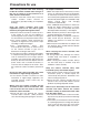
Condensation How to tell when condensation has formed inside and what to do about it If, after the camera recorder’s power has been turned on, the condensation display symbol flashes, it means that condensation has formed inside the camera recorder. If this happens, the power will be automatically turned off after several seconds. Take the following action. 1Remove the cassette. No other functions will work. Depending on the degree of condensation, it may not be possible to eject the cassette, either.
Troubleshooting (Q&A) Power supply-related problems Battery-related problems Q1: A1: No power. Has the battery or AC adapter been connected correctly? Check the connections. (See page 22) Q2: A2: The power goes off on its own. The power will automatically go off if shooting is temporarily stopped for more than 5 minutes in order to prevent the battery from running down and keep the tape from wearing. Check the setting selected for the TAPE PROTECT item on the setting menu OTHER FUNCTIONS screen.
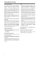
Troubleshooting (Q&A) Problems during various kinds of video recording Q1: No automatic focusing A1-1: Has the manual focus mode been set? The focus is adjusted automatically in the auto focus mode. (See page 12) A1-2: Is a scene which is hard to bring into focus in the auto focus mode being shot? Some scenes are hard to bring into focus using auto focus. In cases like this, use the manual focus mode instead for focusing.
Troubleshooting (Q&A) Playback-related problems (audio) Q1: A1: Q2: A2: Q3: A3: No playback sound is heard from the camera recorder’s speaker. Has the camera recorder’s volume level been set too low? In the VCR mode, press the AUDIO MON/VAR button “+” to increase the volume. (See page 15) More than one recorded stream of sound is heard.
Maintenance Do not use benzine or paint thinners to clean the camera recorder. O Use of benzine or paint thinners may cause the camera recorder body to become deformed or the surface coating to peel off. O When cleaning or otherwise maintaining the camera recorder, either remove its battery or disconnect its AC cable from the power outlet. O Use a soft, clean cloth to wipe the camera recorder.
Specifications [GENERAL] Supply voltage: DC 7.2/7.9 V Power consumption: 6.8 W (when viewfinder is used) 7.8 W (when LCD monitor is used) 9.2 W (max.) indicates safety information. Ambient operating temperature 32°F to +104°F (0°C to +40°C) Ambient operating humidity 10% to 85% (no condensation) Weight 3.731 lb (1.
Specifications [VIDEO] Sampling frequency Y: 13.5 MHz, PB/PR: 3.375 MHz Quantizing 8 bits Video compression system DCT + variable length code Error correction Reed-Solomon product code [AUDIO] Sampling frequency 48 kHz/32 kHz Quantizing 16 bits/12 bits Frequency response 20 Hz to 20 kHz Wow & flutter Below measurable limits [CONNECTORS] VIDEO IN/OUT (input/output automatically switched) Pin jack, analog composite input/output, 1.
Memo
PANASONIC BROADCAST & TELEVISION SYSTEMS COMPANY UNIT COMPANY OF MATSUSHITA ELECTRIC CORPORATION OF AMERICA Executive Office: One Panasonic Way 4E-7, Secaucus, NJ 07094 (201) 348-7000 EASTERN ZONE: One Panasonic Way 4E-7, Secaucus, NJ 07094 (201) 348-7621 Southeast Region: 1225 Northbrook Parkway, Ste 1-160, Suwanee, GA 30024 (770) 338-6835 Central Region: 1707 N Randall Road E1-C-1, Elgin, IL 60123 (847) 468-5200 WESTERN ZONE: 3330 Cahuenga Blvd W.