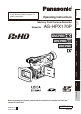
Memory Card Camera-Recorder AG-HPX170P Reference Menu Displays Editing Playback Shooting Preparation Model No. Before use Operating Instructions Description of parts This product is eligible for the P2HD 5 Year Warranty Repair Program. For details, see page 5. Before operating this product, please read the instructions carefully and save this manual for future use.
Read this first! CAUTION RISK OF ELECTRIC SHOCK DO NOT OPEN CAUTION: TO REDUCE THE RISK OF ELECTRIC SHOCK, DO NOT REMOVE COVER (OR BACK). NO USER-SERVICEABLE PARTS INSIDE. REFER TO SERVICING TO QUALIFIED SERVICE PERSONNEL. The lightning flash with arrowhead symbol, within an equilateral triangle, is intended to alert the user to the presence of uninsulated “dangerous voltage” within the product’s enclosure that may be of sufficient magnitude to constitute a risk of electric shock to persons.
indicates safety information. FCC NOTICE (USA) Declaration of Conformity Model Number: AG-HPX170P Trade Name: PANASONIC Responsible Party: Panasonic Corporation of North America One Panasonic Way, Secaucus, NJ 07094 Support contact: Panasonic Broadcast & Television Systems Company 1-800-524-1448 This device complies with Part 15 of FCC Rules.
IMPORTANT SAFETY INSTRUCTIONS 1) 2) 3) 4) 5) 6) 7) 8) 9) 10) 11) 12) 13) 14) Read these instructions. Keep these instructions. Heed all warnings. Follow all instructions. Do not use this apparatus near water. Clean only with dry cloth. Do not block any ventilation openings. Install in accordance with the manufacturer’s instructions. Do not install near any heat sources such as radiators, heat registers, stoves, or other apparatus (including amplifiers) that produce heat.
Software information for this product 1. Customer advisory: This product includes software licensed under the GNU General Public License (GPL) and GNU Lesser General Public License (LGPL); customers have the right to download, modify, and redistribute source code for this software. Descriptions of the GPL and LGPL are stored on the installation CD included with this camera-recorder. See the folder named \LDOC. (The description is the original (written in English).
Contents Read this first!...................................................... 2 IMPORTANT SAFETY INSTRUCTIONS............... 4 Recommendation for Use of Genuine Panasonic Battery Pack (Rechargeable Battery).................................... 4 Software information for this product................ 5 Before use Outline of operations........................................... 8 Precaution for use................................................ 9 Accessories..................................................
Synchro scan.................................................... 50 Switching Audio Input........................................ 51 Using the built-in microphone........................... 51 Using another microphone and audio equipment........................................... 51 Adjusting the recording level............................ 52 Using scene files................................................ 53 Changing scene file settings............................
Outline of operations This unit is compatible with P2 (Professional Plug-in) cards. The P2 card has a large capacity with a high transfer rate, and allows you sophisticated movie-making on this handy camera, including HD (High Definition) recording and smooth editing/dubbing. Video equipment/ Monitor Computer/ Memory card recorder 1 P2 mode shooting and playback (Pages 25 and 63) P2 card The contents can be transferred as a data stream (digital dubbing).
Precaution for use • When shooting important events (such as weddings), always take some trial shots and check that the sound and images have been recorded properly before actual shooting. Be sure to check and set the calendar and time zone. Before use Always take some trial shots before actual shooting. • These settings affect the control and playback sequence of the recorded contents. Before making a recording, set and check the calendar and time zone.
Accessories Battery *1 AC Adapter AC power supply cord/ DC cord Wireless remote control and battery (CR2025) Eye cup Microphone holder Screws for microphone holder 6-mm screws (2) Microphone holder adapter 12-mm screws (2) Shoulder belt Component video cable CD-ROM PIN-BNC conversion plugs (3) 30-mm ferrite core (2)*2 35-mm ferrite core (2)*2 The following accessories are attached to the camera-recorder.
Description of parts Right side and rear side 5 67 8 9 10 11 12 15 16 17 2 1 Description of parts 3 4 1 2 POWER ON OFF 13 14 18 20 22 24 19 21 23 25 1 POWER switch (Page 19) 13 INPUT 1/2 (audio input) switch (Page 51) 2 START/STOP button (Page 25) 14 Zoom ring pin hole (Page 30) 3 REC CHECK button (Page 25) 15 P2 card access lamp (x 2) (Page 26) 4 Zoom button (Page 30) 16 Viewfinder (Page 20) 5 HANDLE ZOOM switch (Page 30) 6 Recording enable/disable switch (Page 40) 17
Description of parts (continued) Left side 1 2 3 4 5 6 7 8 22 23 MENU THUMBNAIL PUSH-SET PAGE/AUDIO MON/VAR 24 25 26 27 BARS 28 SHUTTER CH1 SELECT CH2 SELECT INT(L) INPUT1 INPUT2 INT(R) INPUT2 INPUT1 ON OFF AUDIO COUNTER RESET/TC SET LCD 9 10 AWB 12 14 16 17 18 19 11 1 13 15 Focus ring (Page 35) 2 Zoom ring (Page 30) If you don’t need the zoom ring pin, fit it into the provided zoom ring pin hole (14 on page 11) so that you don’t loose it.
Terminals and mounting parts 5 6 1 2 3 15 16 Description of parts 4 7 SDI OUT 1394 CAM REMOTE 13 FOCUS IRIS COMPONENT ZOOM S/S OUT 8 1 9 10 11 USB terminal (Mini-B) (Page 77) 2 Light shoe 3 Microphone shoe (Page 76) 4 P2 card slots (Page 25) 5 SD memory card slot (Page 29) 6 P2 card eject buttons (Page 28) 7 SDI OUT terminal (Page 80) 8 1394 terminal (Pages 77 and 78) 9 COMPONENT OUT terminal (Page 80) 10 CAM REMOTE jack* FOCUS/IRIS (3.
Description of parts (continued) Remote control The following buttons are for functions that cannot be executed on the camera-recorder. • PHOTO SHOT • TITLE • A.DUB • MULTI/P-IN-P • SELECT • STORE • OFF/ON • PB.ZOOM • INDEX 1 DATE/TIME button (Page 75) 2 OSD button (Page 75) 3 COUNTER button (Page 58) Same function as the COUNTER button on the main unit. 4 COUNTER RESET button (Page 58) Same function as the COUNTER RESET button on the main unit.
The battery Charging 1 2 Align the battery with the marking on the AC adapter, place it flat, and slide it in the direction shown below. • You cannot charge the battery if the DC cord is connected to the DC OUT connector, so disconnect it first. Plug the AC cord into the power outlet. • The POWER lamp and CHARGE lamp on the AC adapter light, and charging begins. • If the CHARGE lamp does not light when attached, detach the battery and then attach it again.
Installing and removing the power supply Installing and removing the battery Installation Removal 1 1 Insert the battery until it clicks into place. 2 Set the POWER switch to OFF, and check that the mode lamp is off. While pressing the battery release button, raise up the battery to remove it. • Support the battery with your hand to ensure that it will not fall.
Adjusting the hand strap Adjust the hand strap to suit your hand. 1 2 Open the cover and adjust the length. Close the cover. • Make sure the cover is fully closed. Attach the shoulder strap and use it as a precaution against dropping the camera. 20 mm or more 20 mm or more Preparation Attaching the shoulder strap Detaching and attaching the lens hood Detaching the lens hood • Turn the lens hood counterclockwise to detach it.
The remote control Insert the battery 1 Push the catch in the direction shown by arrow A to remove the holder. Remote control setup When using two camera-recorders simultaneously, set this camera-recorder and the remote control to either “operation mode 1” or “operation mode 2” so the remote control does not operate the wrong camera-recorder by mistake. Setting 3 Insert the battery with the “+” marked side facing up. Return the holder to its original position.
Turn on/off the camera • Power saving mode When the camera is left idle in pause mode for about 5 minutes, it will behave as follows depending on what POWER SAVE settings have been made in the setting menu OTHER FUNCTIONS screen (Page 112). ON: The camera-recorder turns off automatically. OFF:The camera-recorder does not turn off automatically. See the setup menus, OTHER FUNCTIONS screen, POWER SAVE (Page 112) for details.
Viewfinder This camera has two viewfinders; one is a miniature LCD in the viewfinder and the other is a retractable 3.5-inch LCD. Use the viewfinder that best suits the application and shooting conditions. • The brightness and hue may differ between the images appearing on the viewfinder and LCD monitor and those displayed on a TV monitor. To see how the final images will appear, check them on a TV monitor. • Images are always displayed on the viewfinder.
Using the LCD Set the POWER switch to ON. Hold down the OPEN button to open the LCD monitor. • It can open out to 120 degrees. Do not try to open it further as this will damage the camera. Emphasizing the outlines of the images you see in the viewfinder or on the LCD makes it easier to focus. Emphasizing the outlines does not effect the images you shoot. 1 In CAM mode, press EVF DTL. “EVF DTL ON” appears on the screen for about 2 seconds.
Viewfinder (continued) Adjusting the screen display 1 2 3 Set the POWER switch to ON. (Page 19) Viewfinder adjustments Select YES under EVF SET on the setting menu DISPLAY SETUP screen. DISPLAY SETUP ZOOM·FOCUS CARD/BATT P2CARD REMAIN OTHER DISPLAY LCD BACKLIGHT LCD SET EVF SET SELF SHOOT NUMBER ON TOTAL PARTIAL NORMAL –––– –––– MIRROR PUSH MENU TO RETURN Push the Operation lever in the e or r direction to select the item.
The steps below show how to set the brightness of the LCD monitor to one of three possible levels. 1 2 Select LCD BL under LCD on the setting menu SW MODE screen. This assigns LCD BL to the LCD button. Press the LCD button. Each press of the button switches backlight brightness in the following order: NORMAL (standard) " LOW (dark) " HIGH (bright) " NORMAL. • These settings persist even when the camera-recorder is turned off.
Setting the calendar The CLOCK SET value is recorded in the contents (clip), and affects the sequence of playback of the thumbnails. Before carrying out recording, be sure to check and set CLOCK SET and TIME ZONE. This shows you how to adjust the calendar to 5:20 PM on December 25, 2008. 1 2 3 6 CLOCK SET YEAR MONTH DAY HOUR MIN Set the POWER switch to ON.
Basic shooting operations 3 1 2 3 4 Set the POWER switch to ON. (Page 19) Lift up the viewfinder, press the side of the card slot cover (A), and slide the cover (B) to open it. Insert the P2 card securely in the card slot. 2 Press the START/STOP button (Red) on the POWER switch to start shooting. • Press again to return to the camera to the shooting standby mode. • Use the handle START/STOP button to make it easier to shoot from low angles.
Basic shooting operations (continued) Checking photos taken (REC CHECK) In the shooting pause mode, press the REC CHECK button. This plays back about 2 seconds of the video and audio of the most recently recorded clip before returning to pause mode. • Note that this REC CHECK portion will also be recorded to any equipment you have set up to make backup recordings. • The REC CHECK function does not work in PC and MCR mode. PC mode (1394 HOST) Lights green: Access standby.
4 Press the MENU button. • For menu operation (Page 94) Operation lever MENU PUSH-SET On the menu, select OPERATION and then FORMAT. (Page 68) • A screen such as the one shown below appears. Select the number of the slot into which you inserted the P2 card to be formatted. Select EXIT to cancel the formatting. • When you press the MENU button, the menu display disappears. THUMBNAIL OPERATION MENU button SLOT SEL FORMAT META DATA SLOT2 RE-CONNECTION SD CARD EXCH.
Basic shooting operations (continued) Remove the P2 card 1 2 3 4 Lift up the viewfinder, press the side of the card slot cover (A), and slide the cover (B) to open it. Check that the P2 card access lamp is not blinking orange. Raise the P2 card eject button and press it. Remove the P2 card. • During playback, a P2 card inserted into the empty slot will not be recognized and the P2 card access lamp will not light. When playback is completed, the P2 card recognition will begin.
Using SD/SDHC memory cards You can use SD and SDHC memory cards (the term “SD memory card” is used for both hereafter) to save and load SCENE files and USER files, and to upload clip meta data. (Page 55) THUMBNAIL OPERATION Installing and removing the SD memory card FORMAT META DATA SLOT2 RE-CONNECTION SD CARD EXCH.THUMBNAIL EXIT EXIT Insert the card while making sure it is oriented in the proper direction. 5 Select YES on the confirmation screen. • The selected SD memory card is formatted.
Using the zoom function Zoom button Set the ZOOM switch to SERVO so that you can use the motor-driven zoom. T: Zoom in W: Zoom out Gently press the zoom button on the grip to zoom slowly, firmly press to zoom faster. You can change the zoom speed on the handle zoom button by selecting one of three speeds with the HANDLE ZOOM switch. Set the HANDLE ZOOM switch speeds by going to the setup menus, SW MODE screen HANDLE ZOOM (Page 101). On the remote control Press ZOOM/VOL to zoom with the motor drive.
Variable frame rates (VFR) By taking full advantage of the special characteristics of P2 cards, this unit provides frame skipping (undercranking) recording and highspeed (overcranking) recording, which are actually movie techniques, without the use of a frame rate converter. (Either the 30PN or 24PN mode must be set for this.) Since the camera-recorder records only the effective frames (native recording), recording is possible for between 2 times and 2.
Variable frame rates (VFR) (continued) Native recording 1 2 3 4 32 Using the REC FORMAT function (Page 104) on the RECORDING SETUP screen, select 720P/30PN or 720P/24PN as the recording format. Select the appropriate scene file using the SCENE FILE dial. If necessary, before doing this, perform the camera settings from the setting menu, and register the scene file.
Standard speed shooting for movie production When making movies to show on a screen, a frame rate of 24 fps (frames per second), which is the same as for films, is the norm (1x speed). If you use the settings below, the same kind of playback as with screenings can be obtained. By using the 720P progressive mode and cine-like gamma, high-quality film-like images can be achieved.
Shooting in 1080i/480i progressive mode Selecting 1080i/30P, 1080i/24P, 1080i/24PA, 480i/30P, 480i/24P or 480i/24PA in the REC FORMAT option (Page 104) of the setting menu RECORDING SETUP screen enables shooting in progressive mode. 30P mode: Shoot 30 frames a second in the progressive mode. For output and recording, the 30-framepersecond signal is converted to 60-field-persecond interlace. This mode gives you high quality images.
Shooting in manual mode Set the unit to manual mode when manually adjusting the focus, iris, gain and white balance. Switching to manual mode Slide the AUTO/MANUAL switch to MANUAL to switch to the manual mode. ( A on the viewfinder and LCD go out). 3 Use the FOCUS RING (FOCUS/IRIS) switch to change the function assigned to the focus ring. FOCUS: Adjusts focus. IRIS: Adjusts iris (aperture). • When setting the FOCUS switch to M, also set the FOCUS RING (FOCUS/IRIS) switch to FOCUS.
Shooting in manual mode (continued) Using focus assist Iris adjustments Pressing the FOCUS ASSIST button magnifies the center portion of the image or brings up a frequency distribution graph at the top right of the image to assist during manual focusing. You can use the FOCUS ASSIST setting on the SW MODE screen to change the viewfinder and LCD monitor displays that appear when the FOCUS ASSIST button is pressed.
Adjusting the gain When the display is dark, increase the gain to brighten the display. Light intensity adjustments Use the ND FILTER Switch to change the ND Filter used (filter to change light intensity). OFF: 1/4: 1/16: 1/64: ND filter is not used. Cuts light intensity by up to about 1/4. Cuts light intensity by up to about 1/16. Cuts light intensity by up to about 1/64. ND FILTER switch GAIN switch 2 If the camera is in auto mode, use the AUTO/MANUAL switch to switch to manual mode.
Shooting in manual mode (continued) Adjusting the white balance In order to reproduce the white accurately, adjust the ratio between the three RGB primary colors. If the white balance is not adjusted properly, not only will the white be reproduced poorly but the color tones of the entire screen will also be downgraded. When you are shooting in manual mode, readjust the white balance whenever lighting conditions change. You can save adjustments and reselect them by setting the WHITE BAL switch to A or B.
Use this feature when you have no time to make white balance adjustments. 1 2 3 If the camera is in auto mode, use the AUTO/MANUAL switch to switch to manual mode ( A on the viewfinder and LCD goes out). Set the WHITE BAL switch to PRST. The current white balance value appears. • White balance values 3200 K and 5600 K are preset in the PRST position. Guide to the preset values P3.2K (3200 K): halogen light P5.6K (5600 K): outdoors Press the AWB button. White balance switches between 3200 K and 5600 K.
Shooting techniques for different targets Low-angle shooting Set the Recording enable/disable switch to ON and use the START/STOP button on the handle to make it easier to shoot from low angles. • Set the Recording enable/disable switch to OFF to prevent inadvertent use of the START/STOP button on the handle when this function is not needed.
DISP/MODE CHK button When you hold down the DISP/MODE CHK button during recording standby or recording, all the information including the setting status of the shooting functions and a list of functions allocated to the USER buttons, will be displayed. When you release the button, the normal display will be restored. When you push the DISP/MODE CHK button during recording standby or recording, all the information will be unshown. When you press the button again, the normal display will be restored.
Shooting techniques for different targets (continued) Optical Image Stabilizer Using the USER buttons Use the Optical Image Stabilizer (OIS) to reduce the effects of camera shake when shooting by hand. Press the OIS button to turn the function on and off. appears on the screen when this function is on. Turn the function off when using a tripod for more natural images.
Press the WFM button in CAM mode to display a waveform of the image on the LCD monitor. Pressing the WFM button once again closes the waveform display. • WFM (Page 103) on the setting menu SW MODE screen allows you to switch between the waveform and vector display. • The viewfinder does not show the waveform display. • The waveform does not appear when the focus assist function is used. • The waveform display cannot be recorded.
Shooting techniques for different targets (continued) 2-slot continuous recording If you insert two P2 cards into the two card slots, this function allows you to record continuously on the two cards. You can also record continuously on three or more cards by replacing one card while data is being recorded on the other.
Assign LAST CLIP to any of the USER 1 – 3 buttons to enable a convenient way to delete the last recorded clip. Pressing the USER button to which LAST CLIP was assigned displays a YES/NO confirmation dialog on the screen. Select YES, and the last recorded clip is deleted and “LAST CLIP DELETE OK” is displayed. • Select NO to cancel clip deletion. • Clips cannot be deleted when a switch has been made to the MCR or PC mode or the recording format has been changed after completing a recording.
Using the special recording functions Making the settings in the RECORDING SETUP screen (Page 104) enables special recording functions such as Pre-recording, Interval Recording, One Shot Recording, and Loop Recording. These special recording functions can be used only when the settings below are established.
• Operation is not possible even if only one of the inserted cards is DIR ENTRY NG CARD. (Page 91) • After interval recording has started, a recordable P2 card cannot be used even if it is inserted into an empty slot. • The slots for recording in this mode are indicated by the orange P2 card access lamps. The slots for recording P2 cards that are inserted after starting recording are indicated by the green P2 card access lamps. • Text memos cannot be added.
Using the special recording functions (continued) • This function does not work during 1394 input recording. • The pre-recording function does not work. • Operation is not possible even if only one of the inserted cards is DIR ENTRY NG CARD. (Page 91) • Stopping may take some time. • The following operations are not acknowledged until the P2 card access lamps change from blinking to fully lit up. • The slots for recording in this mode are indicated by the orange P2 card access lamps.
Adjusting the shutter speed SHUTTER button SPEED SELECT button SHUTTER CH1 SELECT CH2 SELECT INT(L) INPUT1 INPUT2 INT(R) INPUT2 LCD 1 2 INPUT1 ON OFF AUDIO COUNTER SPEES SELECT RESET/TC SET INPUT2 ON OFF MIC POWER+48V ZEBRA REC EVF DTL OIS WFM Press the SHUTTER button. Each time you press the SHUTTER button, the shutter speed switches between normal (OFF) and the speed you selected with the SPEED SELECT button.
Adjusting the shutter speed (continued) With artificial lighting and especially fluorescent lights and mercury-vapor lamps, the luminance changes in synchronization with the power line frequency. When this frequency is 50 Hz, mutual interference will occur between the camerarecorder’s vertical sync frequency (approx. 60 Hz) and the lighting frequency (50 Hz). This means that the white balance may change periodically.
Switching Audio Input CH1* CH2** CH3 INT(L): Built-in INT(R): Built-in microphone L microphone R INT(L): Built-in microphone L INPUT1 INPUT2 CH4 INPUT1 INPUT2 INPUT1 INT(R): Built-in microphone R INT(R): Built-in INT(L): Built-in microphone R microphone L INPUT2 INPUT1 INPUT2 INT(L): Built-in INT(R): Built-in microphone L microphone R INPUT2 INPUT2 INT(L): Built-in INT(R): Built-in microphone L microphone R INPUT2 INT(R): Built-in INT(L): Built-in microphone R microphone L INPUT2 * Th
Switching Audio Input (continued) 4 5 Use the CH1 SELECT switch to select the input signal to be recorded to audio channel 1. INT (L): Audio from the built-in microphone Lch is recorded to audio channel 1. INPUT 1: Audio from a device connected to INPUT 1 terminal is recorded to channel 1. INPUT 2: Audio from a device connected to INPUT 2 terminal is recorded to channel 1. Use the CH2 SELECT switch to select the input signal to be recorded to audio channel 2.
Using scene files The settings according to the variety of shooting circumstances are stored in each position of scene file dial. When shooting, you can retrieve the necessary file instantly using scene file dial. Changing scene file settings The setting value of the scene file can be changed. Also you can save the changed scene file to each position of the scene file dial. Example: Change the name of the scene file.
Using scene files (continued) When the screen shown below appears, use the Operation lever to enter a 6character file name. Set the same as user information. (Page 61) • Characters that can be set Space, A to Z, 0 to 9, : ; < = > ? @ [ \ ] ^_-./ When the filename has been set, you can erase all characters using the RESET button on the camera or the remote control.
Saving scene files and other settings on SD memory cards 4 SCENE FILE (SD CARD) FILE SELECT READ WRITE FILE 1 FILE 2 FILE 3 FILE 4 TITLE RELOAD If you have saved a scene file 1 2 Set the unit’s POWER switch to ON. Select SCENE FILE on the setting menu CARD FUNCTIONS screen, select YES and press the Operation lever. (or push it in the q direction) For all other settings, select USER FILE. • For menu operations (Page 94) • You can also use the menu buttons on the remote control.
Saving scene files and other settings on SD memory cards (continued) 6 Press the MENU button four times to cancel the menu mode. To load a file 1) Perform steps 1 to 3, select READ in step 4 and push the Operation lever . When reading is completed, READ OK appears. To title a file 1) Perform steps 1 to 4. 2) Push the Operation lever in the e or r direction to select a character, then push it in the q direction to move to the next character. (The next character can now be selected.
You can add the video and audio systems, name of the videographer, shooting location, text memos and other information to the video data you have recorded on the P2 card. This data is called the clip metadata. (Display method: Page 69) There are two kinds of clip metadata: the data that is recorded automatically during shooting, and the data in the metadata upload file created on the SD memory card which is loaded in the unit.
Using the Counter Counter display You can display a counter that indicates how much time has elapsed during shooting or playback. 1 Press the COUNTER button. Each time you press the button, the display changes as follows. (Page 87) 0 : 00. 00 (CAM mode only) Counter value CLIP 0 : 00.00 (When CLIP is selected for the REC COUNTER item on the DISPLAY SETUP screen) The value is automatically reset at start of shooting and the counter value appears during each shooting session.
Charging the built-in battery/Setting the time data The camera’s internal battery saves the date and time. “ ” appears on the screen of the viewfinder or LCD when the internal battery is running low on charge. Do the following to recharge it. Reset the date and time when fully recharged. 1 2 Specifying the time code (TC PRESET) Set TC PRESET so you can record a value of your choice as the initial setting for the time code to be used at the start of recording. 1 2 Connect the AC adapter.
Charging the built-in battery/Setting the time data (continued) Push the Operation lever in the q direction to move to the next digit, then push it in the e or r direction to select a value. 7 Press MENU twice to exit the menus. MENU TC PRESET MONTH 10h00m00s00f +/– : PUSH q / g SEL : PUSH t / y PUSH MENU TO RETURN You can reset the time code to zero by pressing RESET on the camera or the remote control.
Setting user information allows you to store 8-digit memo (information such as the date and time) in the hexagonal format on the sub code track area. User information is automatically saved in the memory and retained after you turn off the power. 1 2 5 Set the user information. Push the Operation lever in the e or r direction to select user information characters. • You can use numbers from 0 to 9 and letters from A to F. UB PRESET Set the POWER switch to ON.
Charging the built-in battery/Setting the time data (continued) 7 Push the Operation lever in the e direction to move to YES and press it again. UB PRESET PRESET OK? YES ––– PUSH STILL NO 8 Press MENU twice to exit the menus.
Basic playback operations 1 1 POWER ON OFF 2 Lock release 2 SLOT SEL CAM MCR MODE PC Turn the POWER switch to ON. While pressing the lock release, turn the POWER switch to ON. Press the mode button so the MCR lamp turns on. The camera is now in the MCR mode. • Each time you press the button, the mode changes as below. MCR v CAM When you press the mode button while MCR is selected, the unit enters the PC (PC connection) mode.
Thumbnail screen Video data created on the P2 card in one shooting session is called a clip. When the MCR mode has been established, the clips will be displayed on the LCD screen as thumbnails. (When there is a large number of clips, it will take some time for them to be displayed on the screen.) You can perform the following operations using the thumbnail screen. • Play, repair and delete clips, add and delete shot marks, as well as add text memos. • Format P2 cards and SD memory cards.
Slot number display The number of the slot with the P2 card containing the clip indicated by the yellow frame is shown here. (The number appears in yellow.) If a clip extends over the P2 cards in two slots, both numbers will appear in yellow. • When one of the following warnings applies to an inserted P2 card, the frame around the slot number turns pink. 1) RUN DOWN CARD (page 91) 2) DIR ENTRY NG CARD (page 91) 7 Indicators M : Shot mark This indicates that a clip has a shot mark.
Adding shot marks to clips Adding shot marks ( M ) will make it easier to find the clips you are looking for. 1 Push the Operation lever in the w or q direction to move the yellow frame to the clip to which you will add a shot mark. 2 Press the USER button to which the shot mark function has been allocated. (Page 42) To release a shot mark, repeat the above steps.
Thumbnail operations Selecting the thumbnail display method (THUMBNAIL) To delete a text memo: 1) Move the yellow frame to the clip whose text memo is to be deleted, and press the Operation lever. A thumbnail of the text memo now appears. 2) Select the thumbnail of the text memo to be deleted. 3) Press the MENU button to display the menu, and select OPERATIONDELETE. You can display the kind of clips you want to see as thumbnails.
Thumbnail operations (continued) DATE FORMAT: Select year/month/day (YMD), month/day/ year (MDY) or day/month/year (DMY) as the order for displaying the recording date/time. This format will be the same for the recording date displayed by the clip properties and the recording date displayed by DATA DISPLAY. THUMBNAIL SIZE: Select LARGE (3x2) or NORMAL (4x3) for full-screen displays of thumbnails. PLAYBACK RESUME: Resumes playback from the point where a previous playback operations was halted.
4 Press the MENU button to release the menu mode. • When clips have been copied by operating Explorer, for instance, the “ ! ” indicator may appear on the clips. If this happens, “ ! ” can sometimes be released by downloading the latest version of the P2 viewer from the web site given below, installing it in your computer, and copying the clips again. https://eww.pavc.panasonic.co.jp/pro-av/ Checking the clip or card information (PROPERTY) You can perform any of the following operations.
Thumbnail operations (continued) SYSTEM INFO: The version of the system in this camera is displayed. EXIT: Select this to return to the last screen. • Pressing the DISP/MODE CHK button in a thumbnail screen displays the CLIP PROPERTY screen. Press the button again to return to the thumbnail screen. 4 To exit the information screen, press the MENU button, push the Operation lever in the q direction to select EXIT, and press it again.
P2 card remaining memory/total memory The P2 card’s remaining memory and total memory are displayed here in 1-minute increments. Fractions of a minute are rounded off, meaning the display may not match the slot total. 4 Card warning mark This mark is displayed when one of the following warnings applies to a P2 card. 1) RUN DOWN CARD (Page 91) 2) DIR ENTRY NG CARD (Page 91) • The contents of the warning can be viewed by checking the card information as described above.
Thumbnail operations (continued) • When deleting items of LOCATION (shooting location) in SHOOT, items cannot be deleted independently. Make ALTITUDE blank, and the other items (LONGITUDE/LATITUDE) are also deleted. • Metadata of a clip with the incomplete clip indicator cannot be edited. To edit metadata of a clip recorded in multiple P2 cards, insert all the P2 cards containing video data of the clip before starting editing. • If MEMO contains 100 or more characters, it cannot be edited.
PROPERTY: Select this to display the metadata which has been recorded in the unit. Push the Operation lever in the e or r direction, select PROPERTY and push the Operation lever to view the desired data. The Operation lever also allows you to change the data. Changing method is the same as described in “Editing the recorded clip metadata”. (Page 71) EXIT: Select this to return to the last screen. Press the MENU button to release the menu mode.
Useful playback functions Fast forward/rewind playback This function enables you to change the playback speed and search for specific scenes. 1 1 Press the Operation lever in the q (playback) direction during playback. On the remote control, press the VAR. SEARCH button. INDEX SELECT STOP INDEX VAR. SEARCH During playback, push the Operation lever in the t (rewind) or y (fast-forward) direction. This performs fast forward/rewind playback at 4x speed.
Clip skip Push the Operation lever in the t(rewind) or y (fast-forward) direction. REC P-IN-P /REW PLAY A.DUB STOP 2 INDEX Camera or Remote control Adjusting the volume Start playback. To show the information that appears on the viewfinder and LCD, press the OSD button on the remote control. Press the OSD button again to clear the display. THUMBNAIL DATE/ TIME PHOTO SHOT COUNTER RESET TITLE OSD PUSH-SET MULTI/ P-IN-P /REW REC PLAY A.
Connecting external units Headphones 3.5-mm stereo mini jack • Sound is no longer heard from the speaker when the headphones are connected. External microphone Microphone (optional) AG-MC200G Microphone holder Microphone holder adapter 12 mm INPUT1 or INPUT2 6 mm • When attaching an external microphone to the microphone shoe, use the supplied microphone holder and microphone holder adapter.
Computer (non-linear editing/file transfer) When connecting a 1394 cable • Attach the provided two ferrite cores (length: 30 mm) to the both ends of the cable. After passing the cable as shown in the figure on the right, close the ferrite cores until they click into place and lock. Always take sufficient care when handling the ferrite core, as it can be easily damaged when dropped or subjected to other impact.
Connecting external units (continued) When connecting the unit to an Apple Macintosh computer • Connect the 1394 cable after turning on the power of the Apple Macintosh computer. Otherwise, the unit may not be mounted. • The unit may not be recognized after the Apple Macintosh computer has been placed in the hibernation state by its power-saving setting. In this case, disconnect the 1394 cable and then re-connect it.
Digital video equipment (Dubbing) Other Digital video equipment This camera Ferrite core (included) 1394 Ferrite core (included) 6-pin You can connect a digital video unit equipped with a 1394 connector and digitally transfer video and audio signals as well as time code. • Before proceeding to connect or disconnect 1394 cable, be absolutely sure to turn off the power of the units.
Connecting external units (continued) Video deck (Dubbing) Audio cable (optional) White: C H1 (left channel) sound Red: CH2 (right channel) sound BNC cable (optional) VCR SDI OUT COMPONENT OUT Connect one of these cables to the terminal on the video deck. Component video cable (included) Video cable (optional) AUTO REC function When recording is started or stopped on this camera, recording start/stop information can be output through the SDI (HD) connector to control external device.
Nonlinear editing with P2 card (PC mode) The following conditions must be met if the USB cable is to be used to make the connection. • Your computer must run Windows 2000, Windows XP or Windows Vista. • USB dedicated driver (provided on the CD-ROM supplied) must be installed in your computer. • Your computer must support USB2.0 (High Speed, Mass Storage Class). (USB 1.1 is not supported.) • Only one computer can be connected.
Nonlinear editing with P2 card (PC mode) (continued) 6 7 Proceed with nonlinear editing using your computer. An icon for the P2 card contents appears as a removable disk in My Computer of your computer. • For further details, refer to the instructions for your computer’s editing software. • When replacing one card with another, if the USB connection is used, check that the access lamp is not flashing and that the data on the card is not being accessed before ejecting the card.
Copying from P2 cards to the hard disk drive (1394 HOST mode) • Use an HDD (hard disk drive) that has sufficient capacity to permit copying. • Before copying the data, format the hard disk drive so that it can be used by the unit. Bear in mind that this process will delete all the data on the drive. • Connect the camera to an HDD using the 1394 cable. (Page 78) • Do not connect the camera to two or more HDD (chain, hub, etc.), even if they are not turned ON. • Insert the P2 card into the unit.
Copying from P2 cards to the hard disk drive (1394 HOST mode) (continued) To check the HDD status The color of indicates the HDD status, as below. White: HDD is connected and can be used. Black: HDD is not connected. Red: Copy cannot be made to the HDD since it is incorrectly formatted, etc. • When the color is red, correctly format the HDD at step 5 before copying data onto it.
HDD CAPACITY FULL! There is not enough free memory on the HDD. TOO MANY PARTITIONS! There are too many partitions.*1 HDD DISCONNECTED! The HDD has been disconnected. CANNOT FORMAT! Initializing cannot be performed. TOO MANY TARGETS! There are too many 1394 connection destinations. CANNOT ACCESS TARGET! The connection destination cannot be accessed. CANNOT ACCESS CARD! The card cannot be accessed. MISMATCH COMPONENT! There is a mismatch with the connection destination.
Dubbing Digital input/output You can perform dubbing with a high image quality by means of digital signals by using a 1394 cable to connect this unit to a digital video unit equipped with a 1394 connector. 1 2 Connect the digital video equipment to this unit. (Page 78) Press the unit’s mode button to switch to the MCR mode. CAM MCR MODE PC • Cancel the thumbnail screen when in MCR mode. • Set up the connected equipment for playback or recording.
Screen displays Regular displays For details on the safety zone, refer to 38. 36 2 3 4 5 6 8 7 9 1011 12 13 14 15 TC 12 : 34 : 56 : 00 1 2 106 I – PAUSE REMOTE A 32 min USER - 1 HD1080i D10X P 3.2 K 1 8 dB 1394 TC SQU ALC LOW LIGHT ND 1/64 TEXT MEMO R JUN 19 2008 23 : 59 : 59 60 : 24P 1 / 123. 4 SPOT MF23 . 5 ft 1 F 5 .6 Z10 .
Screen displays (continued) 3 AUTO/MANUAL switch operation display This display appears if a function which has been set on the setting menu AUTO SW screen is operating when the AUTO/MANUAL switch has been pressed. 4 Backup unit displays The status of the backup unit connected to the 1394 connector is displayed here. Nothing is displayed if in the setup menus, OTHER FUNCTIONS screen, 1394 CONTROL, you have selected “OFF”.
20 Zoom position display The zoom poison is displayed with Z00 (maximum wide-angle) - Z99 (maximum zoom). The unit can be switched to mm in the ZOOM•FOCUS option of the setting menu DISPLAY SETUP screen. 21 Focus control display Displays the focus control information with 99-00. In the auto focus mode, AF appears. In the manual focus mode, MF appears, and when MF ASSIST is set to ON on the setting menu SW MODE screen, MA appears.
Screen displays (continued) 33 Media remaining memory display Displays the remaining time. • In P2 CARD REMAIN on the setting menu DISPLAY SETUP screen, select TOTAL to display total remaining time for all inserted cards or ONE-CARD (highlighted) to display the time remaining only on the card selected for recording. During MODE CHECK, it is possible to confirm the remaining time for the setting not selected in the menu. • No indication is made while the remaining time is being calculated.
COPY INHIBITED Can not record correctly because of the input signal copy-guarded. EXTERNAL1394 DISCONNECT When the 1394 CONTROL item of the OTHER FUNCTIONS screen of the Setup menu is set to EXT and recording without connecting external units with 1394 terminal, this display appears. INCOMPATIBLE CARD The card cannot be used since it does not comply with the specified standard. RUN DOWN CARD The maximum number of overwrites on the P2 card has been exceeded. Operation continues.
Screen displays (continued) WARNING When trouble occurs with camera systems, WARNING is displayed. FOCUS LOCK (Abnormal focus operation) PSD NG (Abnormal vibration detected) GYRO NG (Abnormal Optical Image Stabilizer control) 1394 This is displayed when trouble has occurred in the 1394 connections or signals.
Setting the DISPLAY items Display the following items on the viewfinder and LCD monitor screen by pressing the DISP/MODE CHK button or by configuring OTHER DISPLAY of the DISPLAY SETUP screen of the setup menus.
Using the setup menus Use the setup menus to change the settings to suit the scenes you are shooting or what you are recording. MENU button Operation lever MENU THUMBNAIL PUSH-SET 2 3 PAGE/AUDIO MON/VAR Push the Operation lever in the e or r direction to move the highlight to the setting you want. Press the Operation lever (or push it in the q direction) to display the items. Example: AUTO SW A.IRIS AGC ATW AF ON 6dB ON ON PUSH MENU TO RETURN 4 Using the menus AUTO SW A.
Initializing the menu settings The menu settings contain both the user file settings and the scene file settings. You can initialize them separately. To initialize the user file (i.e. all the settings other than the scene file settings) Select INITIAL in USER FILE of the OTHER FUNCTIONS screen. The current menu settings of user file will return to the factory settings. To initialize the scene file From the 6 scene files, select the one you want to initialize with the scene dial.
Setup menu structure CAM (camera) mode menu CAMERA MENU SCENE FILE (Pages 98 - 100) CAMERA SETUP (Page 100) ASPECT CONV SETUP SW MODE (Pages 101 - 103) AUTO SW (Pages 103 - 104) A.
Setup menu structure (continued) MCR (playback) mode menu PLAYBACK FUNCTIONS (Page 107) AUDIO OUT AV IN/OUT SETUP (Pages 107 - 108) CMPNT/SDI SEL SDI OUT SDI METADATA SDI EDH DOWNCON MODE DISPLAY SETUP (Pages 108 - 109) OTHER FUNCTIONS (Pages 110 - 112) USER FILE REMOTE PC MODE ACCESS LED CLOCK SET TIME ZONE MENU INIT OPERATION OPTION MENU (Page 112) 1394 STATUS 1394 CONFIG MCR FORMAT 480i MCR MODE 1394 TC REGEN TC MODE TCG TC PRESET 1394 UB REGEN UB MODE UB PRESET 1394 IN PRESET VIDEO OUT OSD DATE
Setup menu list SCENE FILE screen LOAD/SAVE/INIT Display mode (Camera) OPERATION TYPE (Camera) FRAME RATE (Camera) SYNCRO SCAN (Camera) Item 98 DETAIL LEVEL (Camera) V DETAIL LEVEL (Camera) DETAIL CORING (Camera) CHROMA LEVEL (Camera) CHROMA PHASE (Camera) COLOR TEMP Ach (Camera) COLOR TEMP Bch (Camera) MASTER PED (Camera) A.IRIS LEVEL (Camera) Description of settings LOAD: Loads the scene file settings saved using SAVE. SAVE: Saves the changed scene file settings.
SCENE FILE screen (continued) GAMMA (Camera) KNEE (Camera) MATRIX (Camera) SKIN TONE DTL (Camera) Description of settings Selects the DRS (Dynamic Range Stretcher) function. This function compresses the video signal level to extend the dynamic range making it possible to correctly render highlight areas without overexposure and loss of detail that would otherwise occur. OFF, 1, 2, 3 • Larger values indicate a higher compression level of highlight areas. • Only effective in 60i and 60P VIDEO CAM.
Setup menu list (continued) SCENE FILE screen (continued) V DETAIL FREQ Display mode (Camera) NAME EDIT (Camera) Item Description of settings Sets the vertical detail for shooting in 480i progressive mode. THIN: Makes the detail thin. MID: Makes the detail slightly thicker. THICK: Makes the detail thicker.
SW MODE screen HIGH GAIN (Camera) ATW (Camera) HANDLE ZOOM (Camera) IRIS DIAL (Camera) Description of settings Sets the gain value assigned to the M position of the GAIN switch. 0dB, 3dB, 6dB, 9dB, 12dB Sets the gain value assigned to the H position of the GAIN switch. 0dB, 3dB, 6dB, 9dB, 12dB Sets the operation of the ATW (Auto Tracking White Balance) function assigned to the WHITE BAL switch. When the ATW function is set to the AUTO/MANUAL switch or USER button, the operation remains effective.
Setup menu list (continued) SW MODE screen (continued) USER1 Display mode (Camera) USER2 (Camera) USER3 (Camera) Item 102 Description of settings Selects the function assigned to the USER1 button. REC CHECK: Performs Rec Check. SPOTLIGHT: Auto iris control for the spotlight ON/OFF. BACKLIGHT: Auto iris control for the backlight compensation. (Page 42) BLACKFADE: Blackfade (Page 42) WHITEFADE: Whitefade (Page 42) ATW: ATW function ON/OFF.
SW MODE screen (continued) FOCUS ASSIST Display mode (Camera) MF ASSIST (Camera) WFM (Camera) LCD (Camera) Item Description of settings Allocates a function to the FOCUS ASSIST button. EXPANDED: Magnifies the center portion of the image. GRAPH: Displays a frequency distribution graph at the top right in the viewfinder and LCD monitor. BOTH: Magnifies the center portion of the image and displays a histogram. Automatically sets the last focus during manual focusing.
Setup menu list (continued) AUTO SW screen (continued) AGC Display mode (Camera) ATW (Camera) AF (Camera) Item Description of settings Sets the Auto Gain Control when the ON is selected in A.IRIS. 6dB: Performs the Auto Gain Control (max. 6 dB) in auto mode. 12dB: Performs the Auto Gain Control (max. 12 dB) in auto mode. OFF: Does not perform the Auto Gain Control in auto mode. Initiates the control of the gain selected by the GAIN switch.
RECORDING SETUP screen (continued) 25M REC CH SEL (Camera) 1394 TC REGEN (MCR) TC MODE (Camera) (MCR) TCG (Camera) (MCR) TC PRESET (Camera) (MCR) 1394 UB REGEN (MCR) Description of settings Sets the input level of the external microphone connected to the INPUT 2 terminal. (Page 51) -50dB, -60dB Selects the recording audio channel for DVCPRO and DV formats.
Setup menu list (continued) RECORDING SETUP screen (continued) Item UB MODE Display mode (Camera) (MCR) Description of settings Set the content for user information. USER: Records the information of user. TIME: Records the time at recording. DATE: Records the date at recording. TCG: Records the values of the time code generator. FRM. RATE: Records the frame rate information for frame conversion.
PLAYBACK FUNCTIONS screen Item AUDIO OUT Display mode (MCR) Description of settings Sets the audio signals to output from the AUDIO OUT pin jack when the P2 card or the tape is played back.
Setup menu list (continued) AV IN/OUT SETUP screen (continued) Item INT MIC Display mode (Camera) Description of settings Determines whether or not input from the internal microphone is used during recording. ON: Uses internal microphone input. OFF: Does not use internal microphone input.
DISPLAY SETUP screen (continued) Item OTHER DISPLAY CAMERA DATA Display mode (Camera) (MCR) (MCR) LCD BACKLIGHT (Camera) (MCR) LCD SET (Camera) (MCR) (Camera) (MCR) (Camera) EVF SET SELF SHOOT DISPLAY ASPECT (Camera) (MCR) EVF COLOR (Camera) (MCR) REC COUNTER (Camera) Description of settings Select how much information to display on the screen.
Setup menu list (continued) CARD FUNCTIONS screen (continued) Item SD CARD FORMAT Display mode (Camera) Description of settings Formats the SD memory cards. OTHER FUNCTIONS screen Item USER FILE 110 Display mode (Camera) (MCR) REMOTE (Camera) (MCR) 1394 CONTROL (Camera) 1394 CMD SEL (Camera) PC MODE (Camera) (MCR) Description of settings LOAD: Loads the settings in a previously stored user file. SAVE: Saves the updated user file settings.
OTHER FUNCTIONS screen (continued) ACCESS LED Display mode (Camera) (MCR) REC LAMP (Camera) BEEP SOUND (Camera) CLOCK SET (Camera) (MCR) (Camera) (MCR) TIME ZONE Description of settings Sets the access lamp to ON or OFF. ON: The lamp lights up and blinks as per the regular specifications. OFF: The lamp is OFF in all circumstances. Sets lighting of the tally lamp. OFF: The tally lamp does not light. FRONT: Front tally lamp (microphone side) lights. REAR: Rear tally lamp (viewfinder side) lights.
Setup menu list (continued) OTHER FUNCTIONS screen (continued) Item POWER SAVE MENU INIT OPERATION Display mode (Camera) (Camera) (MCR) (Camera) (MCR) Description of settings Selects the power-saving mode when the Operation lever, MENU button, THUMBNAIL button, PAGE/AUDIO MON/VAR button, DISP/ MODE CHK button, USER1-3 buttons and EVF DTL button have not been operated for 5 minutes or so. ON: The camera-recorder’s power is set to OFF. OFF: The unit remains stopped without turning off it’s power.
Before calling for service Power supply There’s no power. • Make sure the battery and AC adapter are connected properly. P16 Check the connections again. Power shuts off for no • To prevent the battery from running down needlessly, the camera- P112 apparent reason. recorder automatically turns off when the camera-recorder has been left in the shooting pause mode for more than 5 minutes. Check the settings in the OTHER FUNCTIONS screen, POWER SAVE. Power goes off as soon as • The battery may have run out.
Before calling for service (continued) Shooting Cannot start shooting. Cannot focus automatically. • Make sure the POWER switch is ON. • You can focus automatically when the auto focus mode is selected. • You may be shooting a scene where it is difficult to bring the subject into focus in the auto focus mode. If this is the case, focus in the manual focus mode.
Playback Cannot play even when I press the play button. • Make sure the MCR lamp is on (press the mode button). P63 No kind of playback operation can be performed unless this lamp is on. Mosaic-like noise appears • This noise is inherent to digital video technology. —— when I cue or review a This is normal. tape. Images do not appear on • Make sure the input selector on your television is set to video —— the television even though input.
Operating precautions Do not allow any water to get into the camerarecorder when using it in the rain or snow or at the beach. • Failure to heed this precaution will cause the camera-recorder or P2 card to malfunction (and may result in irreparable damage). Keep the camera-recorder away from equipment (such as TV sets and video game machines) that generate magnetic fields.
What to remember when throwing memory cards away or transferring them to others Formatting memory cards or deleting data using the functions of the unit or a computer will merely change the file management information: it will not completely erase the data on the cards. When throwing these cards away or transferring them to others, either physically destroy them or use a data deletion program for computers (commercially available) to completely erase the data.
Updating the driver in the camera For the latest information on drivers, visit the P2 Support Desk at the following Web sites. https://eww.pavc.panasonic.co.jp/pro-av/ To update a driver, select PROPERTY on the thumbnail menu and then SYSTEMINFO to check the camera-recorder’s version, go to the site given above, and download the driver as necessary. The updating procedure is completed when the downloaded file has been loaded into the camera-recorder via the SD memory card.
Cleaning Eye cup holder Eye cup Projection Reference When cleaning, do not use benzene or thinner. • Using benzine or paint thinners may deform the camera-recorder and/or cause the surface finish to peel off. • Before proceeding with maintenance, remove the battery or disconnect the AC cord from the power outlet. • Use a soft, clean cloth to wipe the camerarecorder.
Storage Precautions Before storing the camera-recorder, remove the battery. Store all of these items in a place with low humidity and relatively constant temperature. [Recommended temperature range: 15°C to 25°C] [Recommended relative humidity: 40% to 60%] Video camera • Wrap the video camera in a soft cloth to keep the dust off. Battery • The battery life is shortened in places with extreme temperatures.
How to handle data recorded on P2 cards The P2 card is a semiconductor memory card that is used as the recording medium in the professional video production and broadcasting devices that make up the DVCPRO P2 Series. Since data recorded in the DVCPRO P2 format are in a file format, they have excellent compatibility with PCs. The file structure is a unique format, which in addition to video and audio data in MXF files contains various other important information items.
Checkpoints for using memory cards In this unit, use SD memory cards that are compatible with the SD or SDHC standard. When using miniSD or miniSDHC cards in this unit, be sure to use the special adapter. (The unit will not operate correctly if only the adapter is inserted. Always insert a memory card into the adapter.
Recording format list 60 DVCPRO HD Video format 1080i/60i 1080i/60i 720P/60P 720P/60P 720P/30PN 720P/24PN DVCPRO50 DVCPRO DV 480i/60i 720P/60P Native recording 720P/60P Native recording 480i/60i Frame rate 30P 24P 1080i/30P over 1080i/24P over 60i 60i 720P/30P over 720P/24P over 60P 60P 720P/24P 720P/30PN Native recording 720P/30P Native 720P/24PN recording 480i/30P over 60i 24PA 1080i/24PA over 60i — — — 480i/24P over 480i/24PA over 60i 60i Reference Frame rate 12 15 18 20 21 22 24 25 26 27
Appendix Selecting the USER CLIP NAME recording method Press the MENU button and select META DATA PROPERTY USER CLIP NAMEto select the recording method. Two options are available: TYPE1and TYPE2.
Specifications Supply voltage: DC7.2 V/7.9 V Power consumption 10.9 W (when the LCD monitor is not used) 11.7 W (when the LCD monitor is used) 13.8 W (max.) indicates safety information. Ambient operating temperature 0 °C to 40 °C (32 °F to 104 °F) Ambient operating humidity 10% to 85% (no condensation) Weight 1.9 kg (4.2 lb) (excluding battery and accessories) Dimensions (W x H x D) 154 mm x 179.
Specifications (continued) [AUDIO P2] (DVCPRO HD 1080i 720P) Sampling frequency 48 kHz Quantizing 16 bit/4 CH Frequency response 20 Hz to 20 kHz [MEMORY CARD] Video recording formats: DVCPRO HD 1080i/60i (30P over 60i, 24P over 60i, 24PA over 60i) 720P/60P (30P over 60P, 24P over 60P) 720P/30PN (Native recording) 720P/24PN (Native recording) DVCPRO50/DVCPRO/DV 480i/60i (30P over 60i, 24P over 60i, 24PA over 60i) Audio recording formats: PCM digital recording 48 kHz 16-bit 4CH (DVCPRO HD/DVCPRO50) 48 kHz 16-
[AC ADAPTER] Power Source: 100-240 V AC, 50/60 Hz 24 W Power Output: 7.9 V DC, 1.9 A (Video Camera) 8.4 V DC, 1.2 A (Charge) indicates safety information. Reference Weight 160 g (0.35 lb) Dimensions (W x H x D) 70.0 mm x 44.5 mm x 116.0 mm (2-3/4 inches x 1-3/4 inches x 4-9/16 inches) Weight and dimensions are approximate. Specifications are subject to change without notice.
Information on Disposal in other Countries outside the European Union This symbol is only valid in the European Union. If you wish to discard this product, please contact your local authorities or dealer and ask for the correct method of disposal.