Operating Instructions PAL Time Lapse Recorder Model AG- B E Before attempting to connect, operate or adjust this product, please read these instructions completely.
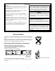
Caution for AC Mains Lead FOR YOUR SAFETY PLEASE READ THE FOLLOWING TEXT CAREFULLY. FOR U.K. ONLY This appliance is supplied with a moulded three pin mains plug for your safety and convenience. A 5 amp fuse is fitted in this plug. Should the fuse need to be replaced please ensure that the replacement fuse has a rating of 5 amps and that it is approved by ASTA or BSI to BS1362. Check for the ASTA mark A A or the BSI mark on the body of the fuse.
Lithium Battery Warning The lithium battery in this equipment must only be replaced by qualified personnel. When necessary, contact your local Panasonic supplier. CAUTION Danger of explosion if battery is incorrectly replaced. Replace only with the same or equivalent type recommended by the equipment manufacturer. Discard used batteries according to manufacturer’s instructions. “The lithium battery is a critical component (type number VL2330/1HF manufactured by Panasonic.
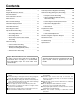
Contents Auto Repeat Recording/Auto Rewinding . . . . . . . 19 Alarm Recording (Emergency Recording) . . . . . . 20 • Principle of Alarm Recording . . . . . . . . . . 20 Features . . . . . . . . . . . . . . . . . . . . . . . 5 Regular Maintenance Service Recommendation . . . . . . . . . . . . . . . . . . . 5 Parts And Their Functions . . . . . . . . . . . . . . 6 Menu Screens . . . . . . . . . . . . . . . . . . . . 9 • Alarm and Display Methods during Alarm Recording . . . . . . . . . . . . . . . .
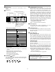
Features Recording and playback up to 336-hour time modes In addition to the 9-hour time modes, recording and playback can be performed in the time lapse modes (L24-, 54-, 72-, 96-, 120-, 168-, 192-, 240- and 336-hour modes). Recording lock function A double recording mode lock function is provided for safeguarding against operational errors during recording.
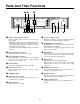
Parts And Their Functions 1 23 4 5 6 7 8 EJECT STOP REV ADV PAGE FWD ADV REW FF TRACKING / V-LOCK RESET t y u 0 (STANDBY/ON) switch The unit is turned on when this switch is pressed. When the switch is pressed again, the unit is in standby mode. STOP button When this is pressed, the tape stops travelling. 3 PAUSE/STILL (PAGE) button When this is pressed during recording, the tape tempo-rarily stops travelling.
y u o RESET button When this button is pressed, the counter display is reset to 0:00:00.
Parts And Their Functions 1 2 3 BATTERY PUSH OPEN CAMERA SW OUT IN IN AUDIO RS-232C VIDEO OUT OUT ALARM RESET IN MIC TAPE END OUT AC IN GND ALARM IN 4 1 COMMON REC IN WARNING/ REC OUT REMOTE 567 8 9 0 q w e r t Camera switching output connector Camera switching output connector; connect it to the frame switcher. • With 9H and L24H modes, the switch timing is below 4 fields.
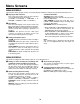
Menu Screens One of the menu screens appears on the TV monitor when the MENU/REC LOCK switch is set to MENU. The display returns to the regular screen when this switch is set to OFF. • When a menu screen has appeared, the items are set using the page, shift and set buttons. • Advance through the pages (page up) of the menu screen using the page button. • Move the items (downward or toward the right) using the shift button. • Change the items (increment or decrement the values) using the set button.
Menu Screens MENU SCREEN 2 The time/date display position, monitor screen blue display and buzzer settings are performed on Menu Screen 2. 5 Display position selection To release the buzzer: ALARM: Release alarm recording. TAPE END: Transfer the mode from the tape end or press the STOP button. TAPE REMAIN: Transfer the mode (but not to PAUSE or REC REVIEW) from the recording mode or press the REC button. ERR WARN: Release the warning status.
MENU SCREEN 4 Recording mode and video output are selected on Menu Screen 4. w Recording time mode selection When recording starts, the set time mode is always established. OFF: The time mode can be set as desired using the time mode button on the VTR’s sub panel. The mode can be changed even during recording.
Menu Screens MENU SCREEN 7 The RS-232C parameters and display language are set on Menu Screen 7. d Setting the bit length (7BIT/8BIT) f Setting the stop bit (STOP-1/STOP-2) g Setting the parity (ODD/EVEN/NON) h Setting the baud rate (4800BPS/9600BPS) j Selection of the menu display language (ENGLISH/FRANÇAIS). • Underline denotes the factory setting. CAUTIONS: • The menu screens are not displayed while the unit is playing back a tape.
Date and Time Settings This unit comes with a time/date generator which enables the date and time to be superimposed on the recording. When the power is switched on, the date, time of the day and time mode are displayed (in the case of a regular screen). TV monitor 1 Date 2 Time mode 9 3 Time STOP 4 Alarm display PLAY 1 Date: PAUSE/STILL MENU OFF REC LOCK REV ADV PAGE The date appears as day/month/year.
Date and Time Settings 7 When the MENU/REC LOCK switch is set to OFF, the clock automatically starts running from time and date set. TIME 03- 3-01 3:25:00 54H Flashing For the seconds, “00” is set. Even when the switch is set to MENU, the time will keep advancing if it has not been changed. • To clear the date and time display, set POSITION under (DISPLAY) on Menu Screen 2 to OFF.
Time Mode Selection EJECT REC REVIEW REC REC PULL OPEN FWD REV TRACKING / V-LOCK RESET TIME MODE COUNTER / SEARCH ALARM TIME MODE button Refer to the table given below to select the mode that suits the intended purpose of use. Recording enable time (in hours) Mode 180-minute tape 120-minute tape Video recording interval (in seconds) Audio recording Camera switchover interval (in seconds) Possible 1/25 Tape replacement standard (recording times) 9H 9 6 1/50 L24H 24 16 0.
Recording Procedure 1 Switch on the power to the connected equipment. 5 Set the timer recording, auto repeat recording, alarm recording, restoration-of-power-after-failure recording or other recording function. 2 Adjust so that the images of the video cameras appear properly on the TV monitor. 6 Select the time mode for the recording. 3 Check that the date and time displayed on the TV 7 Press the REC button. monitor have been adjusted properly.
Timer Recording There are two methods of timer recording: one uses the internal timer and the other uses an external timer. Internal Timer Recording Start time and stop time Bear in mind the following points when setting these times. • When the stop time is set later than the start time: Recording will commence at the start time on the day concerned and stop at the end time on the same day.
Timer Recording Daily Recording (Daily Timer)/Weekly Recording (Weekly Timer) Example: When recording from 8:30 to 12:00 from Sunday through Thursday and from 9:00 to 12:00 on Fridays and Saturdays 1 Check that OFF or ON for Sunday (SUN) is 6 When the shift ( flashing. If the setting is OFF, press the set (+, –) buttons to display ON.
External Timer Recording The unit can be made to record using an external timer to turn on its power. EJECT REC REVIEW REC REC AG-RT850 PULL OPEN FWD REV TRACKING / V-LOCK RESET TIME MODE Power Cord (supplied) COUNTER / SEARCH ALARM (Audio timer available from dealer) To AC IN Timer External timer recording operations 1 Check that a video cassette with its tab intact has 2 Set the TIMER MODE (REC MODE) switch to EXT been inserted. TIMER so that EXT lights on the display.
Alarm Recording (Emergency Recording) When an emergency occurs at the monitoring site during prolonged monitoring and recording, the alarm function is automatically triggered, and alarm recording is performed.
Alarm Recording Operation 4 Press the shift ( ) button to move the flashing to 1 Check that a video cassette with its tab intact has been inserted. DURATION. Press the set (+ or –) button to set the recording duration. 2 Set the MENU/REC LOCK switch to MENU to display the menu screens. Press the page button to display the alarm recording setting screen (Menu Screen 3) on the TV monitor. [ALARM] 5 Upon completion of the settings, set the MENU/ REC LOCK switch to OFF. The regular screen is restored.
Playback Procedure Before operating the unit, check that the internal/external timer recording displays (INT/EXT) have been cleared from the display. (If INT or EXT is displayed, set the TIMER MODE switch to OFF to clear it.) 1 Switch on the power to the unit and TV monitor. 4 Press the PLAY button. 2 Insert the recorded cassette tape into the unit. 3 Select the time mode. Notes on operation 1.
Routine & Regular Inspection Request This unit is designed to withstand many hours of operation. Nevertheless, it is recommended that routine inspections be conducted to help ensure trouble-free operation. CAUTION Do not forget to conduct the routine inspection with auto repeat recording. Routine inspection procedure 1 Set the power switches on the unit, video cameras, TV monitor and other equipment connected in the monitoring system to the ON position.
RS-232C Interface 1. Outline of RS-232C interface This interface is for enabling the basic functions of the VTR to be operated using a personal computer. • The D-SUB 9P connector is used to connect the VTR with the personal computer. 2. Hardware specifications ■ D-DUB 9-pin connector specifications D-DUB 9P, female • Connector: • Compatible cable: Straight cable D-SUB 9P input signals Pin No. Abbreviation 1 CD (DCD) Carrier detection PC receives this signal.
3. Protocol ■ Receiving format (personal computer → VTR) General format: stx command [:data] [;command [:data]] etx stx: 02h (HEX) ; (semicolon): 3Bh command delimiter command: ccc ccc: command (3 ASCII characters) : (colon): 3Ah parameter delimiter data: parameter (any number: based on command) etx: 03H In some cases, the format does not contain what is enclosed in the square brackets.
RS-232C Interface ■ Table of commands Command Counter reset Eject Fast forward Pause/still Play Record Rewind Forward search Reverse search Stop Field advance (+) Field advance (–) Power ON Power OFF Recording check Tracking (+) Tracking (–) Auto tracking Time setting Time mode switching Key lock setting Display switching Version request Communication check Counter data request ID request Status request All status request Time mode request Display status request Key lock request ACK return ON ACK return OFF
Details of commands Counter data request command This requests the current value on the CTL counter. PC: [STX] QCD [ETX] VTR: [STX] CDCwghmmss g: for a minus amount, space for a plus amount hmmss: hours/minutes/seconds W: S; for STOP, EJECT, STILL, FWD ADV and REW ADV. P; for modes other than the above. Time mode switching command This sets the time mode during deck recording/playback. However, when REC T-MODE has been set, it takes precedence over the other modes during recording.
RS-232C Interface ACK return status request command This is for verifying the ACK return status. PC: [STX] QRA [ETX] ∗: N = ON F = OFF VTR: [STX] RA∗ [ETX] All status request command When the all status request command has been received, the current deck status is detected and sent by the bitmap shown below. PC: [STX] QOS [ETX] VTR: [STX] OPS abcdef [ETX] ab Counter commands Bit 7 cc: Returns fixed value.
Troubleshooting Trouble with installation • Is the power plug inserted properly into the AC outlet? • Is the unit connected properly with the TV, video cameras, etc.? • Are any of the connecting cables making faulty contact? • Has the focus on the video cameras been adjusted correctly? No power. No picture. Indistinct picture.
Troubleshooting No timer recording. • Are the present time and start/stop times for the timer No alarm recording. • Has INT or EXT lit on the display? • Have the alarm sensors and alarm input connectors been recording correct? connected properly? • Has the alarm recording mode been selected on Menu Screen 3? Trouble with playback Noise sometimes appears on the playback pictures. Dirty playback picture. • Adjust the tracking buttons. (See page 22) “Snow” on playback picture.
Specifications Power Source: Power Consumption: 220 – 240 V AC, 50 – 60 Hz 20 W is the safety information. Audio General Operating Temperature: Operating Humidity: Dimensions: Line Input (Phono): Mic Input (3 mm): Line Output (Phono): Tracks: Recording mode: Playback mode: 5°C to 40°C 35% to 80% 430 (W) × 86.5 (H) × 293.5 (D) mm (excluding rubber legs) 3.85 kg Weight: Video Recording/ Playback System: 4 rotary heads, helical scanning azimuth recording system, VHS format Tape Speed: 7.
Matsushita Electric Industrial Co., Ltd. Web Site: http://www.panasonic.co.