
Operating instructions


8
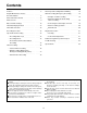
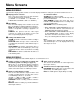
Camera switching output connector
Camera switching output connector; connect it to
the frame switcher.
Audio input/output connectors
Audio input/output connectors (phono jacks)
Video input/output connectors
Video input/output connectors (BNC); connect the
input connector to the video camera, etc. and the
output connector to the TV monitor, etc.
AC IN connector
Connect the supplied power cord to an AC outlet.
Alarm input connector
Alarm recording input connector; connect it to the
external sensor.
COMMON terminal
Alarm reset input connector
Input connector for releasing alarm recording; a +4
to +14 V DC voltage is required.
REC IN connector
Input connector for recording
Tape end output connector
When the cassette tape comes to its end during
recording, the alarm device installed externally is
activated.
WARNING/REC output connector
When trouble has occurred in the unit, the alarm
device installed externally is activated.
Error warning or recording low signal selected on
the menu screen 3 is output.
GND Terminal
This terminal is connected to the signal ground
terminal of the connected unit in order to reduce
noise. It is not connected to ground for safety
purposes.
MIC input jack
Input jack (3 mm) for an external microphone.
This jack has precedence when signals are
supplied simultaneously to this jack and the audio
input connectors.
REMOTE control connector
For connecting the AG-A11 remote controller which
is available as an optional accessory.
Battery installation area
Install the battery in this area. See “Lithium Battery”
on page 3.
1
2
3
4
5
6
7
8
9
0
q
w
e
r
Parts And Their Functions
12
67 9
80
w
q
e
3
4
5r
BATTERY
PUSH OPEN
CAMERA
IN
OUT
TAPE END OUT
WARNING/
REC OUT
REC IN
COMMON
ALARM RESET IN
ALARM IN
AUDIO
IN
OUT
VIDEO
GND
SW OUT
MIC
REMOTE
AC IN