
Datasheet


–1–
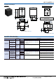
ASCTB360E 201505-T
Compact size 2 Form A and
2 Form A 1 Form B 35A power
relays for energy management
and industrial equipment
HE-S RELAYS
Protective construction: Flux-resistant type
TYPICAL APPLICATIONS
• Photovoltaic power generation systems (Solar inverter)
• Uninterruptible Power Supplies (UPS)
• Inverter
• Office air conditioner
• Industrial equipment
RoHS compliant
FEATURES
1. High-capacity and long life 35A 277V AC 5×10
4
(long life
type)
2. Electrical life (resistive load)
3. Compact size and low operating power
W: 30 × L: 36 × H: 40 mm W: 1.181 × L: 1.417 × H: 1.575 inch
Operating power: 1,880 mW (holding power: 170 mW)
4. Reduced coil holding voltage contributes to saving
energy of equipment
The coil holding voltage can be reduced up to 30%V of the
nominal coil voltage. This equals to operating power of
approximately 170 mW, which contributes equipment energy
savings.
* Coil holding voltage is the coil voltage after 100 ms from the applied nominal coil
voltage.
5. Contact gap: 3.2 mm .126 inch (VDE0126 compliant)
Compliant with European photovoltaic standard VDE0126
Compliant with EN61810-1 2.5 kV surge breakdown voltage
(between contacts)
6. Insulation distance (initial)
• Between Form A contact and coil: Min. 11.0 mm .433 inch
(Clearance/Creepage)
• Between Form B contact and coil: Min. 3.2 mm .126 inch
(Clearance/Creepage)
• Between contact sets: Min. 8.2 mm .323 inch (Clearance/
Creepage)
7. Contact gap (initial)
• Form A contact: Min. 3.2 mm .126 inch/each 1a contact
• Form B contact: Min. 0.7 mm .028 inch
Min. 0.5 mm .020 inch (When Form A contact
welded)
8. Mirror contact mechanisms (Compliant with EN60947-4-1
mirror contact)
Form A contact Standard type Long life type
35A 277V AC
30A 220V AC
20A 277V AC
3×10
4
—
1×10
5
5×10
4
1×10
5
2×10
5
Detection of contact welding makes it possible to
construct a safety circuit.
• Designed so that Form A contact and Form B contact will
not close at the same time.
• Designed so that a contact interval of at least 0.5 mm .020
inch is maintained.
* Form B contact, when used to monitor the condition of Form A contact, can be
used exclusively as an auxiliary contact.
Condi-
tions
Normal operation
When Form A
contact welded
Non-excitation Excitation Non-excitation
Mirror
contact
mecha-
nisms
Open
Form B
contact
Form A
contact
Closed
Form B
contact
Form A
contact
OpenClosed
Form B
contact
Form A
contact
OpenClosed
Welding
Min. 0.5 mm
Min. .020 inch
New