Order No: PHAAM1111120A1 Outdoor Unit CU-2E18NBU Please file and use this manual together with the service manual for Model No. CS-E9NKUAW CS-E12NKUAW, Order No. PHAAM1111087C1. WARNING This service information is designed for experienced repair technicians only and is not designed for use by the general public. It does not contain warnings or cautions to advise non-technical individuals of potential dangers in attempting to service a product.
13.4 13.5 13.6 13.7 13.8 13.9 13.10 13.11 13.12 13.13 13.14 13.15 13.16 Electronic Parts Temperature Rise Protection 2 (Cool)......................................23 Cooling overload control (Cool)..................24 Heating overload control (Heat) .................24 Extreme Low Temperature Compressor low pressure protection control (Heat)..............24 Deice Control..............................................25 Time Delay Safety Control (Restart Control) .........................................
1. Safety Precautions Read the following “SAFETY PRECAUTIONS” carefully before perform any servicing. Electrical work must be installed or serviced by a licensed electrician. Be sure to use the correct rating of the power plug and main circuit for the model installed. The caution items stated here must be followed because these important contents are related to safety. The meaning of each indication used is as below.
18. For R410A models, when connecting the piping, do not use any existing (R22) pipes and flare nuts. Using such same may cause abnormally high pressure in the refrigeration cycle (piping), and possibly result in explosion and injury. Use only R410A materials. Thickness of copper pipes used with R410A must be more than 1/32". Never use copper pipes thinner than 1/32". It is desirable that the amount of residual oil is less than 0.0014 oz/32.8ft. 19.
2. Specifications 2.1 CU-2E18NBU Item Unit Indoor Unit Combination 3.2kW + 3.2kW 1 Phase, 208 – 230V, 60Hz (Power supply from outdoor unit) Power Source Capacity Running Current Cooling Operation OUTDOOR UNIT Electrical Data Power Input EER 4.89 (2.10 ~ 5.86) BTU/h 16700 (7200 ~ 20000) A 7.6 - 6.9 kW 1.45 (0.39 ~ 1.84) W/W 3.37 (5.38 ~ 3.18) BTU/hW 11.50 (18.45 ~ 10.85) dB-A 48 dB 62 kW 5.94 (2.11 ~ 7.20) BTU/h 20200 (7200 ~ 24600) A 9.0 - 8.1 kW 1.85 (0.42 ~ 2.29) W/W 3.
Air Volume Item Unit High m /min (ft /min) 3 OUTDOOR UNIT 3 37.2 (1313) Refrigerant Control Device Expansion Valve Refrigerant Oil FV50S Refrigerant (R410A) g (oz) Cooling Indoor Operation Range Heating Cooling Outdoor Operation Range Heating 1.92k (67.8) Dry Bulb Wet Bulb Maximum °C (°F) 32 (89.6) 23 (73.4) Minimum °C (°F) 16 (60.8) 11 (51.8) Maximum °C (°F) 30 (86.0) — Minimum °C (°F) 16 (60.8) — Maximum °C (°F) 43 (109.4) 26 (78.8) Minimum °C (°F) 16 (60.
Indoor unit combination Outdoor Unit Operation Mode Operation Class (kW) One-room Operation CU-2E18NBU 2.8 Cooling Capacity (kW) 2.8 + 3.2 Min ~ Max Rating Min ~ Max 2.82 1.81 ~ 3.27 850 390 ~ 1020 4.5 4.1 0.5 3.21 1.85 ~ 3.75 1000 390 ~ 1230 5.2 4.7 0.6 4.89 2.09 ~ 5.86 1450 390 ~ 1920 7.6 6.9 0.5 + 0.5 4.89 2.10 ~ 5.86 1450 390 ~ 1870 7.6 6.9 0.5 + 0.6 4.89 2.10 ~ 5.86 1450 390 ~ 1840 7.6 6.9 0.6 + 0.
3.
4.
5.
6.
7.
8. Printed Circuit Board 8.
8.2 Noise Filter Printed Circuit Board 8.
9. Installation Information 9.1 Check Points QUICK GUIDE PIPING AND ELECTRICAL SPECIFICATION Indoor (ID) & Outdoor (OD) units: Possible Combination Patterns Outdoor (OD): CU-2E18NBU Indoor (ID): 2 UNITS OF CSE9NKUAW Outdoor (OD): CU-2E18NBU Indoor (ID): 2 UNITS OF CSE12NKUAW Outdoor (OD): CU-2E18NBU Indoor (ID): 1 UNIT OF CSE9NKUAW + 1 UNIT OF CS-E12NKUAW Piping size Capacity Refrige(Btu/h) rant 16700 Gas Liquid Ø3/8” Ø1/4” R410A (Ø9.52mm) (Ø6.35mm) Min. total Min. AddiMax. pipe pipe Standard Max.
10. Installation Instruction 10.1 Select The Best Location 10.1.1 Outdoor Unit If an awning is built over the unit to prevent direct sunlight or rain, be careful that heat radiation from the condenser is not obstructed. There should not be any animal or plant which could be affected by hot air discharged. Keep the spaces indicated by arrows from wall, ceiling, fence or other obstacles. Do not place any obstacles which may cause a short circuit of the discharged air.
Outdoor Unit Installation Guidelines Where a wall or other obstacle is in the path of outdoor unit’s intake or exhaust airflow, follow the installation guidelines below. For any of the below installation patterns, the wall height on the exhaust side should be 47-1/4" or less. 10.2 Install The Outdoor Unit After selecting the best location, start installation to Indoor/Outdoor Unit Installation Diagram. 1 Fix the unit on concrete or rigid frame firmly and horizontally by bolt nut (ø13/32").
CUTTING AND FLARING THE PIPING 1 Please cut using pipe cutter and then remove the burrs. 2 Remove the burrs by using reamer. If burrs is not removed, gas leakage may be caused. Turn the piping end down to avoid the metal powder entering the pipe. 3 Please make flare after inserting the flare nut onto the copper pipes. 10.4 Evacuation of the Equipment WHEN INSTALLING AN AIR CONDITIONER, BE SURE TO EVACUATE THE AIR INSIDE THE INDOOR UNIT AND PIPES in the following procedure.
10.5 Connect The Cable To The Outdoor Unit 1 2 3 4 5 6 7 Remove Control Board Cover (Metal) by loosening 2 screws. Remove Valve Cover (Metal) by loosening 2 screws. Remove Plugs. Fix the conduit connectors to the knock out holes with lock-nuts, then secure them. Connecting wire between indoor unit and outdoor unit should be UL listed or CSA approved 4 conductor wires minimum AWG16 in accordance with local electric codes. Wire Connection to the power supply (208/230V 60Hz) through circuit breaker.
11. Operation Control 11.1 Cooling Operation 11.1.1 When cooling operation is enabled, based on outdoor ambient temperature, fan motor control will be adjusted according to figure below: 11.1.2 Outdoor fan control Annual Cooling control This control is to enable cooling operation when outdoor ambient temperature is low. Control start conditions: o Cooling operation is activated with compressor ON.
11.2 Heating Operation 11.2.1 Outdoor fan control When heating operation is enabled, based on outdoor ambient temperature, fan motor control will be adjusted according to figure below: To improve the judgment accuracy, indoor room temperature sampling starts when any indoor unit has stopped capability supplied (heating thermo-off) during heating operation with compressor ON, outdoor unit will send signal to all thermo-off indoor units to ON fan motor and get room temperature sample.
12. Simultaneous Operation Control 1 2 3 4 Operation modes which can be selected using the remote control unit: Automatic, Cooling, Soft Dry, Heating, e-ion operation mode.
13. Protection Control 13.1 Freeze Prevention control (Cool) When received freeze prevention signal from indoor unit, the compressor frequency changes according to indoor heat exchanger temperature. When indoor unit request capability OFF due to freeze condition , immediately the capability supply to targeted indoor unit stops. 13.
13.5 Cooling overload control (Cool) This control detect outdoor pipe temperature and perform the compressor frequency restriction during cooling operation. 13.6 Heating overload control (Heat) This control detect indoor pipe temperature and perform the compressor frequency restriction during heating operation. This control detect outdoor ambient temperature and perform the fan speed adjustment during heating operation. 13.
13.8 Deice Control When outdoor pipe temperature and outdoor air temperature is low, deice operation starts where indoor fan motor and outdoor fan motor stop, indoor unit horizontal vane close and operation LED blink with compressor ON. 13.9 Time Delay Safety Control (Restart Control) The compressor will not restart within three minutes after compressor is stopped. This control is not applicable if the power supply reset or after deice condition. 13.
13.13 Compressor Protection Control (Gas leak detection control 1) Control start conditions o For 5 minutes, the compressor continuously operates and total current is low. o During Cooling or Soft Dry operation: Indoor intake temperature — indoor piping temperature is below 39.2°F. o During Heating operation: Indoor pipe temperature — indoor intake temperature is below 37.4°F. o Not during deice control. o Compressor ON with maximum frequency.
14. Servicing Mode 14.1 CU-2E18NBU 14.1.1 Pump down operation (SW1) Operate the pump down process according to the following procedure o Confirm the valve on the liquid side and gas side are open. o Press PUMP DOWN button (SW1) on the Service PCB inside the outdoor unit for more than 5 seconds. Pump down (cooling) operation is performed for 15 minutes. o Set the liquid side 3 way valve to close position and wait until the pressure gauge indicates 1.45PSI (0.1kg/cm2G).
14.1.3 Wiring Error check The unit capable to correct the wiring error automatically by following procedures. o Confirm the valve on the liquid side and gas side is open. o Press WIRING CHECK button (SW3) on the Service PCB inside the outdoor unit for more than 10 seconds to start wiring check operation. o Wiring check process will complete in approximately 10 minutes. However, wiring check operation will not start within 3 minutes after compressor is stopped.
15. Troubleshooting Guide 15.1 Self Diagnosis Function The display screen of wireless remote control unit and the self-diagnosis LEDs (green) on the outdoor printed circuit board in the outdoor unit can be used to identify the location of the problem. Refer to the table below to identify and solve the cause of the problem, and then re-start the air conditioner system. If the problem is solved and operation returns to normal. LED 1 illuminates and others LED are off.
16. Disassembly and Assembly Instructions WARNING High Voltage are generated in the electrical parts area by the capacitor. Ensure that the capacitor has discharged sufficiently before proceeding with repair work. Failure to heed this caution may result in electric shocks. 16.1 Outdoor Unit Removal Procedure Caution! When handling electronic controller, be careful of electrostatic discharge. 16.1.1 1 2 16.1.
16.1.3 6 7 8 9 16.1.4 1 2 Removing the Control P.C. Board Remove the drip proof cover. Disconnect the connectors (lead wires of the compressor, sensor, and others). Remove the screw at the right side of the control box, and pull out the entire control box. Release the control P.C. Board tab to remove the control P.C. Board. Removing the Propeller Fan and Fan Motor Follow the steps in 16.1.1 for removing the cabinet top plate and cabinet front plate.
3 4 Disconnect the fan motor connector from the control P.C. Board. Loosen the 4 fan motor mounting screws then remove the fan motor.
17. Technical Data 17.1 Operation Characteristics 17.1.1 One Indoor Unit Operation Cooling Characteristic [Condition] Room temperature: 81°F (DBT), 66°F (WBT) Operation condition: High fan speed Piping Length: 24.6ft Compressor Freq: Fc A) Indoor unit capacity: Cooling (2.8: CS-E9NKUAW), service mode frequency = 28Hz 208 230 60.000 Outlet Air Temperature (°F) 59.000 58.000 57.000 56.000 55.
Cooling Characteristic [Condition] Room temperature: 81°F (DBT), 66°F (WBT) Operation condition: High fan speed Piping Length: 24.6ft Compressor Freq: Fc B) Indoor unit capacity: Cooling (3.2: CS-E12NKUAW), service mode frequency = 33Hz 208 230 60.000 Outlet Air Temperature (°F) 59.000 58.000 57.000 56.000 55.000 54.000 53.000 60 65 70 75 80 85 90 95 100 105 110 115 100 105 110 115 100 105 110 115 100 105 110 115 Outdoor Air Temperature (°F) 4.200 Cooling Capacity (kW) 4.
Piping Length Characteristic Cooling [Condition] Room temperature: 81°F (DBT), 66°F (WBT) Operation condition: High fan speed Outdoor temperature: 95°F (DBT) Compressor Freq: Fc A) Indoor unit capacity: Cooling (2.8: CS-E9NKUAW), service mode frequency = 28Hz 208 230 Outlet Air Temperature (°F) 59.500 59.000 58.500 58.000 57.500 9 14 19 24 29 34 39 44 49 54 59 64 69 74 79 84 Piping Length (ft) 3.000 Cooling Capacity (kW) 2.900 2.800 2.700 2.600 2.
Piping Length Characteristic Cooling [Condition] Room temperature: 81°F (DBT), 66°F (WBT) Operation condition: High fan speed Outdoor temperature: 95°F (DBT) Compressor Freq: Fc B) Indoor unit capacity: Cooling (3.2: CS-E12NKUAW), service mode frequency = 33Hz 208 230 58.500 Outlet Air Temperature (°F) 58.000 57.500 57.000 56.500 56.000 55.500 9 14 19 24 29 34 39 44 49 54 59 64 69 74 79 84 59 64 69 74 79 84 59 64 69 74 79 84 59 64 69 74 79 84 Piping Length (ft) 3.
Heating Characteristic [Condition] Room temperature: 68°F (DBT) Operation condition: High fan speed Piping Length: 24.6ft Compressor Freq: Fh Heating overload protection: 38Hz (Outside air 75.2°F) A) Indoor unit capacity: Heating (2.8: CS-E9NKUAW), service mode frequency = 52Hz 208 230 113.200 Outlet Air Temperature (°F) 108.200 103.200 98.200 93.200 88.
Heating Characteristic [Condition] Room temperature: 68°F (DBT) Operation condition: High fan speed Piping Length: 24.6ft Compressor Freq: Fh Heating overload protection: 44Hz (Outside air 75.2°F) B) Indoor unit capacity: Heating (3.2: CS-E12NKUAW), service mode frequency = 52Hz 208 230 113.000 Outlet Air Temperature (°F) 108.000 103.000 98.000 93.000 88.
Piping Length Characteristic Heating [Condition] Room temperature: 68°F (DBT) Operation condition: High fan speed Outdoor temperature: 47°F (DBT), 43°F (WBT) Compressor Freq: Fh A) Indoor unit capacity: Heating (2.8: CS-E9NKUAW), service mode frequency = 52Hz 208 230 112.000 Outlet Air Temperature (°F) 111.000 110.000 109.000 108.000 107.000 106.000 9 14 19 24 29 34 39 44 49 54 59 64 69 74 79 84 Piping Length (ft) 4.200 Heating Capacity (kW) 4.100 4.000 3.900 3.800 3.700 3.
Piping Length Characteristic Heating [Condition] Room temperature: 68°F (DBT) Operation condition: High fan speed Outdoor temperature: 47°F (DBT), 43°F (WBT) Compressor Freq: Fh B) Indoor unit capacity: Heating (3.2: CS-E12NKUAW), service mode frequency = 52Hz 208 230 110.000 Outlet Air Temperature (°F) 109.000 108.000 107.000 106.000 105.000 104.000 103.000 102.000 9 14 19 24 29 34 39 44 49 54 59 64 69 74 79 84 Piping Length (ft) 4.600 Heating Capacity (kW) 4.500 4.400 4.300 4.
17.1.2 Two Indoor Unit Operation Cooling Characteristic [Condition] Room temperature: 81°F (DBT), 66°F (WBT) Operation condition: High fan speed Piping Length: 24.6ft Compressor Freq: Fc A) Indoor unit capacity: Cooling (2.8 + 2.8: CS-E9NKUAW + CS-E9NKUAW), service mode frequency = 48Hz 208 230 61.000 Outlet Air Temperature (°F) 60.000 59.000 58.000 57.000 56.
Cooling Characteristic [Condition] Room temperature: 81°F (DBT), 66°F (WBT) Operation condition: High fan speed Piping Length: 24.6ft Compressor Freq: Fc B) Indoor unit capacity: Cooling (3.2 + 3.2: CS-E12NKUAW + CS-E12NKUAW), service mode frequency = 46Hz 208 230 62.000 Outlet Air Temperature (°F) 61.000 60.000 59.000 58.000 57.000 56.
Cooling Characteristic [Condition] Room temperature: 81°F (DBT), 66°F (WBT) Operation condition: High fan speed Piping Length: 24.6ft Compressor Freq: Fc C) Indoor unit capacity: Cooling (2.8 + 3.
Piping Length Characteristic Cooling [Condition] Room temperature: 81°F (DBT), 66°F (WBT) Operation condition: High fan speed Outdoor temperature: 95°F (DBT) Compressor Freq: Fc A) Indoor unit capacity: Cooling (2.8 + 2.8: CS-E9NKUAW + CS-E9NKUAW), service mode frequency = 48Hz 208 230 60.400 Outlet Air Temperature (°F) 60.200 60.000 59.800 59.600 59.400 59.200 59.000 58.
Piping Length Characteristic Cooling [Condition] Room temperature: 81°F (DBT), 66°F (WBT) Operation condition: High fan speed Outdoor temperature: 95°F (DBT) Compressor Freq: Fc B) Indoor unit capacity: Cooling (3.2 + 3.2: CS-E12NKUAW + CS-E12NKUAW), service mode frequency = 46Hz 208 230 61.700 Outlet Air Temperature (°F) 61.200 60.700 60.200 59.700 59.200 58.
Piping Length Characteristic Cooling [Condition] Room temperature: 81°F (DBT), 66°F (WBT) Operation condition: High fan speed Outdoor temperature: 95°F (DBT) Compressor Freq: Fc C) Indoor unit capacity: Cooling (2.8 + 3.
Heating Characteristic [Condition] Room temperature: 68°F (DBT) Operation condition: High fan speed Piping Length: 24.6ft Compressor Freq: Fh A) Indoor unit capacity: Heating (2.8 + 2.8: CS-E9NKUAW + CS-E9NKUAW), service mode frequency = 65Hz 208 230 119.000 Outlet Air Temperature (°F) 114.000 109.000 104.000 99.000 94.000 89.000 84.000 3 8 13 18 23 28 33 38 43 48 53 58 63 68 73 78 58 63 68 73 78 58 63 68 73 78 58 63 68 73 78 Outdoor Air Temperature (°F) 8.
Heating Characteristic [Condition] Room temperature: 68°F (DBT) Operation condition: High fan speed Piping Length: 24.6ft Compressor Freq: Fh B) Indoor unit capacity: Heating (3.2 + 3.2: CS-E12NKUAW + CS-E12NKUAW), service mode frequency = 63Hz 208 230 118.000 Outlet Air Temperature (°F) 113.000 108.000 103.000 98.000 93.000 88.000 83.000 3 8 13 18 23 28 33 38 43 48 53 58 63 68 73 78 58 63 68 73 78 58 63 68 73 78 58 63 68 73 78 Outdoor Air Temperature (°F) 9.
Heating Characteristic [Condition] Room temperature: 68°F (DBT) Operation condition: High fan speed Piping Length: 24.6ft Compressor Freq: Fh C) Indoor unit capacity: Heating (2.8 + 3.
Piping Length Characteristic Heating [Condition] Room temperature: 68°F (DBT) Operation condition: High fan speed Outdoor temperature: 47°F (DBT), 43°F (WBT) Compressor Freq: Fh A) Indoor unit capacity: Heating (2.8 + 2.8: CS-E9NKUAW + CS-E9NKUAW), service mode frequency = 65Hz 208 230 Outlet Air Temperature (°F) 97.000 96.900 96.800 96.700 96.600 96.
Piping Length Characteristic Heating [Condition] Room temperature: 68°F (DBT) Operation condition: High fan speed Outdoor temperature: 47°F (DBT), 43°F (WBT) Compressor Freq: Fh B) Indoor unit capacity: Heating (3.2 + 3.2: CS-E12NKUAW + CS-E12NKUAW), service mode frequency = 63Hz 208 230 Outlet Air Temperature (°F) 95.000 94.500 94.000 93.500 93.000 92.
Piping Length Characteristic Heating [Condition] Room temperature: 68°F (DBT) Operation condition: High fan speed Outdoor temperature: 47°F (DBT), 43°F (WBT) Compressor Freq: Fh C) Indoor unit capacity: Heating (2.8 + 3.
18. Exploded View and Replacement Parts List Note The above exploded view is for the purpose of parts disassembly and replacement. The non-numbered parts are not kept as standard service parts.
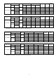
REF. NO.
74 ACCESSORY CO. (DRAIN ELBOW) 1 CWG87C900 76 77 NUT - TERMINAL COVER 2 CWH7080300J TERMINAL COVER 1 CWH171035 78 TUBE ASS'Y (LIQUID 1) 1 CWT026284 79 TUBE ASS'Y (LIQUID 2) 1 CWT026285 80 MANIFOLD TUBE ASS'Y (GAS) 1 CWT07K1522 81 CLIP FOR SENSOR HOLDER 4 CWH711010 82 BAG 1 CWG861154 83 BASE BOARD-COMPLETE 1 CWG62C1081 84 SHOCK ABSORBER - RIGHT 1 CWG712879 85 SHOCK ABSORBER - LEFT 1 CWG712880 86 C.C.