
user manual


19
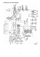
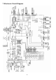
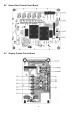
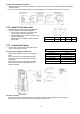
10.5 Connect The Cable To The Outdoor Unit
1 Remove Control Board Cover (Metal) by
loosening 2 screws.
2 Remove Valve Cover (Metal) by loosening
2 screws.
3 Remove Plugs.
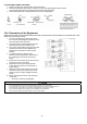
4 Fix the conduit connectors to the knock out
holes with lock-nuts, then secure them.
5 Connecting wire between indoor unit and
outdoor unit should be UL listed or CSA
approved 4 conductor wires minimum AWG16
in accordance with local electric codes.
6 Wire Connection to the power supply
(208/230V 60Hz) through circuit breaker.
o Connect the UL listed or CSA approved
wires minimum AWG12 to the terminal
board, and connect to other end of the
wires to circuit breaker.
7 Connect the power supply cord and
connecting wires between indoor unit and
outdoor unit according to the diagram as
shown.
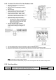
8 For wire stripping and connection requirement, refer to the diagram below.
9 Secure the power supply cord and connecting cables onto the control board with the holder.
10 Attach the control board cover (metal and resin) and valve cover back to the original position with screw.
This equipment must be properly earthed.
Earth wire shall be Yellow/Green (Y/G) in colour and longer than other AC wires for safety reason.
10.6 Heat Insulation
Liquid-side pipes
Use a material with good heat-resistant properties as the heat insulation for the
pipes. Be sure to insulate both the gas-side and liquid-side pipes. If the pipes are
not adequately insulated, condensation or water leakages may occur.
Gas-side pipes
Material shall
withstand
248°F or higher