Digital Video Cassette Recorder AJP Operating Instructions
IMPORTANT “Unauthorized recording of copyrighted television programs, video tapes and other materials may infringe the right of copyright owners and be contrary to copyright laws.” WARNING: CAUTION To reduce the risk of fire or shock hazard, do not expose this equipment to rain or moisture. RISK OF ELECTRIC SHOCK DO NOT OPEN CAUTION: TO REDUCE THE RISK OF ELECTRIC SHOCK, DO NOT REMOVE COVER (OR BACK). NO USER-SERVICEABLE PARTS INSIDE. REFER SERVICING TO QUALIFIED SERVICE PERSONNEL.
Contents General and Features ...............................................4 Controls and their functions ...................................... 6 • Front panel .............................................................. 6 • Front panel top section ......................................... 7 • Front panel center section .................................... 8 • Front panel bottom section .................................14 • Connector area .....................................................
General and Features This unit is a digital video cassette recorder which uses 1/4-inch tapes. It incorporates digital compression technology so that the deterioration in picture quality and sound quality resulting from dubbing is significantly minimized compared with existing analog systems. Furthermore, since it has a compact 4U size and light weight, the unit can be carried around or mounted in a 19-inch rack with ease.
Features (continued) Recording and playing back V blanking data In addition to closed caption and VITC, up to 28 lines of the character data per frame in the V blanking period can be recorded and played back. There is some limitation to the number of lines in which signals can be recorded. Time codes This unit comes with a built-in time code generator (TCG)/time code reader (TCR).
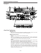
Controls and their functions Front panel q w r e t EJECT INPUT SELECT ON VIDEO Y PB PR CMPST SDTI(V&A) SDI AUDIO ANALOG AES/EBU USER SET SDI u AUTO OFF $3 OFF POWER y #6 !8 !9 @0 @1@3 @2 CH CONDITION TC MODE INT TAPE TC $7 #8#$ 9 0 $1 $2 L MONITOR SELECT R LEVEL $6 DV W CUE CH2 VIDEO REC #4 SCH ASSEMBLE UB CH2 CUE TC TRIM SET IN OUT + REW REV LOCAL PLAYER SHTL !3 STOP @7 FWD RECORDER !7 SERVO PLAY EDIT A – EE !6 #5 A IN EXT STAND BY RESET INS
e INPUT SELECT display The characters corresponding to the selected input signal light. When, with the exception of analog signals, the selected input signals are not available, the display flashes to alert the user.
Controls and their functions (continued) i PLAY button Playback commences when this button is pressed. Recording commences when the button is pressed together with the REC button; manual editing commences when it is pressed together with the EDIT button during playback. Pressing only the PLAY button during manual editing will cut out the editing and establish the playback mode. o REC button Recording commences when this button is pressed together with the PLAY button.
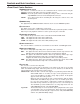
!6 STAND BY button When this is pressed, the same tension as in the regular stop mode is applied to the tape, and while the head drum continues to rotate, the button’s lamp lights to indicate that the standby ON mode is established. In the standby OFF mode, the half-loading mode is established. When this button is pressed in the stop mode, the standby OFF mode is established, the half-loading mode is established. The lamp in the button now goes off.
Controls and their functions (continued) @2 REMOTE/LOCAL switch This switch is set when the unit is to be controlled from an external source using the REMOTE connector, RS-232C connector or parallel connector. REMOTE: Set to this position when controlling the unit by a device connected using the 9-pin REMOTE connector or RS-232C/parallel connector. LOCAL: Set to this position when controlling the unit using the controls on its own operation panel.
@9 PREROLL button This is used for feeding and cueing the tape for manual editing. When it is pressed, the tape travels to the preroll point where it stops. The preroll time can be set on the setup menu No. 000 (P-ROLL TIME). When this button is pressed while the IN or OUT button is held down, the tape can be cued to the IN or OUT point entered. When the AUTO ENTRY on the setup menu No.
Controls and their functions (continued) #7 Time code buttons These are used to set the TC or UB value. SHIFT: When setting the TC or UB value, first press this button to stop the data running. Change the digit now flashing on the display. Each time the button is pressed, the flashing moves to the right by one digit, and when it reaches the right-most digit, it returns to the left-most digit. When it is kept depressed, the flashing moves consecutively.
$6 Volume control This is used to adjust the headphones volume and the monitor output volume. Whether the headphones output and monitor output volumes are to be linked or kept separate can be set on the setup menu No. 708 (MONI OUT). (Note that the headphones output volume is normally linked.) When the volumes are kept separate, the monitor output is set to the unity value (preset value).
Controls and their functions (continued) $9 ENCODER CONTROL switch This selects whether the adjustments to the video output signals are to be performed by the unit or by an external encoder/remote controller. REMOTE: The adjustments to the video output signals are performed by the external encoder/remote controller. LOCAL: The adjustments to the video output signals are performed by the unit.
%7 REC INHIBIT switch This selects whether to enable or inhibit the recording on the cassette tape. ON: The recording on the cassette tape is inhibited. The REC INHIBIT lamp on the front panel now lights. OFF: The recording on the cassette tape is enabled provided that the cassette’s accidental erasure prevention mechanism has been set to the recording enable position.
Controls and their functions (continued) Connector area r t i o !9 ANALOG CH1 CH2 r REMOTE INPUT VIDEO IN Y REMOTE IN/OUT ON AUDIO IN 75Ω P B TIME CODE IN CH1 REMOTE OUT ~AC IN CUE OUT REF VIDEO IN 75Ω !0 !1 Y OFF RS-232C VIDEO OUT L @0 CH 1/2 PUSH 1 DIGITAL CH 1/2 IN DIGITAL OUT SDI/ SDTI PARALLEL MONITOR R 1 P B SDI/ SDTI 2 IN P R w ENCODER REMOTE ON OUTPUT AUDIO OUT q P R y u CH2 TIME CODE OUT OFF CUE IN 3 SIGNAL GND AUDIO OUT SDI/ SDTI 2 @1 @2 SDI/
q AC IN connector This is for connecting the unit to the power outlet using the power cord provided. w SIGNAL GND terminal This terminal is connected to the signa unit which is connected to the unit in order to reduce noise. It is not connected to ground for safety purposes. e Fuse holder This contains a fuse. r Fan motor This is for cooling the unit. The W lamp lights when trouble has caused the fan motor to stop.
Controls and their functions (continued) !5 ANALOG COMPONENT VIDEO OUT connector The analog component video signal is output from this connector. !6 ANALOG COMPOSITE VIDEO OUT connectors The analog composite video signals are output from these connectors. The video signal with signals superimposed on it can be output from the VIDEO OUT3 connector. The superimpose function can be set ON or OFF on the setup menu No. 006 (SUPER).
Connections when one unit is used Set the CONTROL switch on the front panel to LOCAL.
Connections when 2 units are used (deck to deck) Source machine: • Set the CONTROL switch on the front panel to REMOTE. Recorder: • Set the CONTROL switch on the front panel to LOCAL.
Connections with editing controller Recorder AV monitor Video monitor signals Audio monitor signals Video monitor signals Audio input signals Remote To REMOTE IN/OUT connector Video input signals Audio monitor signals AV monitor Editing controller Reference signal generator To REMOTE IN/OUT connector Reference signal Remote Audio output signals Video output signals Audio output signals Remote Video output signals AV switcher To REMOTE IN/OUT connector Reference signal AV monitor Audio
Connections for adjusting video output (encoder output) signals REF (BB) Player 1 (source machine 1) REF VIDEO IN Player 2 (source machine 2) REF (BB) REF VIDEO IN VIDEO 1 OUT REF (BB) RECORDER REF VIDEO IN VIDEO IN VIDEO 1 OUT REF (BB) P1 IN REF IN P2 IN Switcher Make these two cables equally long. RECORDER OUT MONITOR OUT q Supply the external reference signal from a sync signal generator to the units. w Use the composite connectors for the video signals.
Tapes Type Description Tape designed exclusively for the camcorders used by consumers in general. Only playback is possible using the optional cassette adaptor. Consumer However, please note that long-play cassette tapes (80-minute standard/ cassette 120-minute LP mode) cannot be used. (S cassette) Use of Panasonic consumer DV cassette tapes is recommended. Note that inserting a cassette tape without using the cassette adaptor can damage the unit.
Switching on the power/inserting the cassette Before starting to operate the unit, check whether the equipment has been connected properly. 1 2 3 4 Turn on the power. Check that the AUTO OFF lamp is off. When condensation has formed or some other trouble has occurred, the AUTO OFF lamp lights, and all operations are disabled. Insert the cassette tape. Insert the tape at its proper position without force. Check that the STOP lamp is on.
STOP/STAND BY mode 1 2 When the STOP button is pressed, the unit goes into the stop mode. The STOP lamp lights and the tape stops traveling. • In order to protect the tape, the unit goes into the standby OFF mode after the time set by setup menu No. 400 (STILL TIMER) has elapsed. When the STOP, REW, FF or PLAY button is pressed, the unit will go into the appropriate mode. When the STAND BY button is pressed, the unit goes into the standby ON/OFF mode.
Recording 1 2 3 4 5 6 7 Set the accidental erasure prevention tab on the cassette tape to the “recording” position and insert the tape. Press the STOP button to place the unit in the stop mode. Set the TAPE/EE switch to EE. EE images now appear on the TV monitor. Check that the REC INHIBIT lamp is off. If this lamp is lighted, set the REC INHIBIT switch to OFF. Select the video and audio input signals and adjust their levels. 5-1 Selecting video/audio input signals 1 Connect the signals to be recorded.
Playback 1 2 3 4 Insert the cassette tape, and place the unit in the stop mode. Press the PLAY button. Regular playback is now commenced. Adjust the audio playback level. Pull out the audio level controls and turn them clockwise or counterclockwise to adjust the levels. Normally, they are kept in the pushed-in state (unity value). To end playback, press the STOP button. The VTR now goes into the stop mode. Check that the SERVO lamp is lighted during playback.
Jog/shuttle Jog mode 1 2 3 Push the search dial to the “in” position. Be sure that the JOG lamp lights. Rotate the search dial. The dial’s clickstops are cleared, and the tape is played back at the speed corresponding to the speed at which the dial is turned. The maximum speed can be selected using the setup menu No. 320 (JOG FWD MAX) and No. 321 (JOG REV MAX) settings. When the dial rotation is stopped, a still picture appears. The playback picture is noise-free.
Manual editing 1 2 3 4 5 Select the editing mode. ASSEMBLE: For assemble editing. INSERT: For insert editing. Select the editing channel. In the case of insert editing, press the channel button corresponding to the signals to be edited, and check that its lamp is on. Press the PLAY button. Search for the position where the editing is to be commenced (IN point) while viewing the TV monitor, and press the PLAY and EDIT buttons together at the IN point.
Preroll 1 Press the PREROLL button. The VTR now performs the preroll operation. • When the edit IN point has been entered, the tape is rewound from the edit IN point for the duration set by setting menu “000,” and the unit then goes into the stop mode. • When the edit IN point has not been entered, the tape is rewound for the duration set by setting menu “000” from the position where the button was pressed, and the unit then goes into the stop mode.
Automatic editing (Deck to Deck) Editing refers to the job of using a prerecorded tape to produce a complete recording by joining together separate cuts and deleting unnecessary parts. The basic steps taken for editing are as follows. 1 2 3 4 Set the CONTROL switch to REMOTE on the player and to LOCAL on the recorder. Select the editing mode. Enter the edit points of the recorder and player. Check and modify the edit points. 5 Check (Preview) before proceeding with the editing.
Automatic editing Switch settings and adjustments When the unit is used as the recorder: Select the video and audio input signals using the INPUT SELECT switches. Set the POWER switch to ON. Set the CONTROL switch to LOCAL.
Select the editing mode 1 2 3 Select the editing mode. For assemble editing, press the ASSEMBLE button. For insert editing, press the INSERT button. ASSEMBLE: The assemble editing mode (in which cuts are joined together) is established. INSERT: The insert editing mode (in which cuts are inserted) is established. Select the editing channel. With assemble editing, the ASSEMBLE lamp lights. With insert editing, press the button of the channel whose signals are to be edited and lights its lamp.
Automatic editing Entering the edit points 1 2 3 4 Search for the edit IN point by performing the jog or shuttle operation. Establish the still picture mode at the desired position. Refer to page 28 for details on the jog/shuttle operations. Press the SET button while holding down the IN button. The edit IN point is now entered. The edit IN point value now appears on the display. Search for the edit OUT point by performing the jog or shuttle operation.
Checking the edit points 1 2 3 Press the IN (or OUT) button to check the edit point. The value of the entered edit point appears on the display. Press the PREROLL button while holding down the IN (or OUT) button to check the image at the edit point. The tape is cued at the edit IN (or OUT) point, and the still picture mode at that point is displayed. • The EE mode is established if the TAPE/EE switch has been set to the “EE” position when “STOP” has been selected for the setup menu No.
Automatic editing Modifying the edit points 1 2 3 Re-entering the edit points Search for the new edit point by performing the jog or shuttle operation, and press the IN (or OUT) and SET buttons together to re-enter the edit point. Modifying the edit point in frame units (trim function) Press the TRIM button while holding down the IN (or OUT) button. The edit point is put ahead by 1 frame each time the + button is pressed. The edit point is put back by 1 frame each time the – button is pressed.
Preview 1 After the edit points have been entered, press the PREVIEW button. Normal preview is now performed. • If the edit IN point has not been entered, the position where the PREVIEW button was pressed will be entered at the edit IN point. • To stop the preview at any time, press the STOP button. • If the PREVIEW button is pressed again while preview is in progress after the IN point, preview will start again from the beginning.
Automatic editing Executing automatic editing 1 Press the AUTO EDIT button. Automatic editing is now performed. • To stop the editing at any time, press the STOP button. • When the edit OUT point is reached, the unit goes into the stop mode after postrolling. Postroll With assemble editing, editing continues for approx. 2 seconds even after the edit OUT point has been passed, the tape is rewound to the OUT point, and the unit goes into the stop mode.
Review 1 Upon completion of the editing, press the REVIEW button. The review is started in the recorder. • To stop the review at any time, press the STOP button. • When the edit OUT point is reached, the unit goes into the stop mode after postrolling.
Split editing Split editing refers to editing where the editing channels are switched while insert editing is in progress. 1 2 Perform insert editing. Switch the editing channel. When, for instance, sound from AUDIO CH2 is to be additionally inserted during video channel insert editing: 2-1 Press the AUDIO CH2 button during video channel editing. The lamp in the button lights and the AUDIO CH2 sound is insert edited. 2-2 Press the AUDIO CH2 button again and turn off the lamp in the button.
Audio split editing The video edit points and audio edit points can be entered separately, and they can be offset from each other and edited. Audio edit points can be entered, deleted and revised only when the insert editing mode has been selected. After the edit points have been entered, follow the same operating procedure as that for insert editing. ■ Entering the edit points Video IN point: Video OUT point: Audio IN point: Audio OUT point: Press the SET button while holding down the IN button.
Audio split editing ■ Displaying the audio split edit points The edit points are displayed on the front panel as shown below. (The figure shows an audio IN point.) Operations Video IN point: Video OUT point: Audio IN point: Audio OUT point: Press the IN button. Press the OUT button. Press the A IN button. Press the A OUT button.
Voice-over facility (internal) Operating procedure 1 ANALOGUE AUDIO IN* MIC AMP VIDEO OUT Microphone TV monitor * Connect to the channel whose sound is to be recorded. 1 2 3 4 5 6 7 8 9 10 11 12 AJ-D850 Select INT_VO as the setup menu No. 322 (AUD MEM MODE) setting. Select the same setting for the channel (CH1 or CH2) on which the sound is to be recorded and for the setup menu No. 323 (AUD MEM CH) channel. Insert the cassette tape for which the voice-over editing is to be performed.
Voice-over facility (internal) Operating procedure 2 1 2 3 4 5 6 7 8 Select INT_VO as the setup menu No. 322 (AUD MEM MODE) setting. Select the same setting for the channel (CH1 or CH2) on which the sound is to be recorded and for the setup menu No. 323 (AUD MEM CH) channel. Insert the cassette tape for which the voice-over editing is to be performed. Press the insert button for the channel (CH1 or CH2) on which the sound is to be recorded and ensure that its lamp lights.
For operation with an editing controller (AG-A850) MIC AMP Microphone * Connect to the channel (CH1 or CH2) on which the sound is to be recorded. ANALOGUE AUDIO IN* VIDEO OUT REMOTE IN/OUT TV monitor AJ-D850 Ref. RECORDER CONTROLLER AG-A850 1 2 3 Select INT_VO as the setup menu No. 322 (AUD MEM MODE) setting. Select the same setting for the channel (CH1 or CH2) on which the sound is to be recorded and for the setup menu No. 323 (AUD MEM CH) channel.
Audio cross channel editing (internal) Example: To record cross-faded audio signals onto CH2 ■ Connections PLAYER RECORDER EDITING CONTROLLER AG-A850 Ref REMOTE IN/OUT INPUT A AUDIO OUT INPUT B PLAYER AJ-D750 + REMOTE IN/OUT MIXER CH1 OUT AUDIO CHI1 IN MIXER CH2 OUT AUDIO CHI2 IN MIXER IN Event 1 AUDIO CHI1 OUT RECORDER AJ-D850 OUT CH1 Fig. 1 CH2 Event 2 IN Up to 20 sec. CH1 insert start CH1 Fig. 2 CH2 Cross fading by operating the mixer 1 2 3 Select INT_X as the setup menu No.
4 Enter the edit points of the first event on the player’s tape. 5 Enter the edit points of the first event on the recorder’s tape. 6 7 8 9 10 11 12 13 14 15 Operate the mixer in such a way that the player’s audio output signals are output from the mixer’s CH1 OUT and CH2 OUT connectors. (The same audio signals will be delivered through CH1 and CH2 of the mixer.) Press the AUTO EDIT button. The first event is now recorded on the recorder’s tape. (See Fig. 1.
V blanking data recording/playback ■ Additional line recording/playback function • Select the mode for recording signals in additional lines using setup menu item No. 800 (ADD LINE). Off: No signals are recorded in additional lines. YC422: The input signals are recorded in 1 line in the 422 mode. YC411: The input signals are recorded in 1 line in the 411 mode. Y1_B/W: The input signals are recorded in 1 line in their original form as the luminance signal.
Video output (encoder output) signal adjustments After this system has been connected, the video output signal (ENCODER OUT) must be adjusted if AB roll editing (editing using two source machines) using an editor, for instance, is to be error-free and accurate. (This adjustment must be repeated when one of the connecting cables has been replaced and whenever the connections are changed.) The adjustment procedure using this unit is outlined below. 1 2 3 Check the connections. (See page 22.
Setup (default settings) The unit’s major settings are performed by making selections on menus. The setting menus appear on the TV monitor when the TV monitor and VIDEO OUT 3 connector in the unit’s connector area are hooked up. Changing the settings 1 2 3 4 5 6 Press the MENU button. The setup menu appears on the TV monitor and setup menu No. appears on the counter display. (If the setup has already been performed, the screen showing the changes made last will appear.
Setup (setting) menus This unit can store up to 5 user files (user 1 to user 5) containing different menu settings, and these files can be selected and used. Changing the file 1 2 Press the MENU button. Hold down the STAND BY button and press the FF button to switch to the next user file. Hold down the STAND BY button and press the REW button to switch to the previous user file.
Setup menus Lock mode can be set to protect the settings in the system files and user files (USER2 – USER5). Settings can no longer be changed when this mode is set. To set and release the lock mode for the system files and user files use setup item No. 30 (MENU LOCK) and setup menu item No. A03 (MENU LOCK), respectively. Setting and releasing the lock mode. 1 2 3 4 Press the MENU button.
The contents of the USER2 – USER5 files can be copied (loaded) into the USER1 file. In addition, the contents of the USER1 file can be copied (saved) to the USER2 – USER5 files. Load or save USER1 Load or save Load or save Load or save USER2 Settings can be locked. USER3 Settings can be locked. USER4 Settings can be locked. USER5 Settings can be locked. Loading a user file 1 2 3 Press the MENU button. While holding down the STANDBY button, press the REW or FF button, and select USER1.
Setup menus Saving a user file 1 2 3 Press the MENU button. While holding down the STAND BY button, press the REW or FF button, and select USER1. Turn the search dial and move the cursor ( * ) on the menu screen to setup item No. A01 (SAVE). SETUP-MENU MENU NO.A00 - 0000 803 TELETEXT DET AUTO A00 LOAD USER2 *A01 SAVE USER2 A02 P.ON LOAD OFF END 4 5 While holding down the search button, turn the search dial and select the user file into which the USER1 contents are to be saved.
Setup (setting) menus SYSTEM menu Item Setting Description No. Superimposed display 00 SYS SC 0000 .. . 0127 .. . 0255 –127 .. . .. 0 . 128 System phase adjustment: Total variable range: ±180° or more –: Advanced +: Delayed If setting operation is performed, the setting value does not return to factory (default) setting. 01 SYS H 0000 ... 0032 .. . 0060 –30 ... .. 0 .
Setup (setting) menus SYSTEM menu (continued) Item Setting Description No. Superimposed display 10 AV PHASE 0000 .. . 0128 .. . 0255 –128 .. . .. 0 . 127 This adjusts the audio output phase with respect to the video output: 20.8 µs steps –: The audio output phase is advanced with respect to the video output. +: The audio output phase is delayed with respect to the video output.
Setup menus USER menu Item No. Superimposed display Setting No. Description Superimposed display 000 P-ROLL TIME 0000 . .. 0005 .. . 0015 0S . .. 5S .. . 15S This sets the preroll time which can be set from 0 to 15 seconds in 1-second increments. When the unit is set to automatic editing [PREVIEW, AUTO EDIT], the unit will not operate if the preroll time is set to 0 seconds. 001 CHARA H-POS 0000 .. . 0005 .. . 0011 .. 0 . .. 5 .
Setup menus USER menu (continued) Item No. Superimposed display Setting No. Description Superimposed display 004 LOCAL ENA 0000 0001 0002 DIS ST&EJ ENA 005 TAPE TIMER 0000 0001 ±12h 24h 006 SUPER 0000 0001 OFF ON This selects whether the time code and other super display which are output to the VIDEO OUT 3 connector is to shown. 0: Not shown. 1: Shown.
USER menu Item No. Superimposed display Setting No. Description Superimposed display 100 SEARCH ENA 0000 0001 DIAL KEY This selects the direct search dial operation. 0: For direct search dial operations. 1: Operation is not transferred to the search mode unless the search button is pressed. 101 SHTL MAX 0000 0001 0002 ×16 ×32 ×60 This sets the maximum speed for shuttle operations.
Setup menus USER menu (continued) Item No. Setting Superimposed display No. Description Superimposed display 108 FORMAT SEL 0000 0001 0002 DVCPRO DV DVCAM These settings are for selecting the format when an L cassette or S cassette is used.
USER menu (continued) Item No. Superimposed display Setting No. Description Superimposed display 115 STOP RESPNS 0000 0001 NORMAL QUICK This selects the response when the mode is changed to STOP/STILL while the tape is traveling. 0: Priority is given to the output picture. 1: Priority is given to the response. • At the 1 (QUICK) setting, the picture may not be as clear in the STOP/STILL mode as it would be at the 0 (NORMAL) setting. • CTL may shift by ±2 frames.
Setup menus USER menu Item Setting Description No. Superimposed display 200 PARA RUN 0000 0001 DIS ENA This selects whether two or more VTRs are to be operated in synchronization. 0: No operation in synchronization 1: Operation in synchronization When operating two or more VTRs in synchronization, set item 200 of all the VTRs to 0001. 201 9P SEL 0000 0001 OFF ON This selects whether the 9P connector functions when the REMOTE/LOCAL switch has been set to REMOTE.
USER menu Item No. Superimposed display Setting No. Description Superimposed display 301 IN/OUT DEL 0000 0001 MANU AUTO This selects the operation to be performed when an edit point has been set incorrectly (when the OUT point is before the IN point). 0: Editing is not executed unless the illegal edit point is cleared or set again properly. 1: The edit points already input are automatically cleared.
Setup menus USER menu (continued) Item No. Superimposed display Setting No. Description Superimposed display 308 CONFI EDIT 0000 0001 OFF ON This selects whether to conduct simultaneous playback while editing is in progress. 0: No simultaneous playback 1: Simultaneous playback Simultaneous playback is valid when the TAPE/EE switch is set to TAPE. 309 AUD EDIT IN 0000 0001 CUT FADE This selects the connection method for the digital audio edit IN point.
USER menu (continued) Item No. Superimposed display Setting No. Description Superimposed display 318 VAR REV MAX 0000 0001 0002 0003 0004 0005 0006 0007 –4.1 –1.85 –1 –0.43 –0.3 –0.2 –0.1 –0.03 This sets the maximum VAR REV speed. 0: –4.1× (–3.1×) speed 1: –1.85× (–1.85×) speed 2: –1× (–1×) speed 3: –0.43× (–0.5×) speed 4: –0.3× (–0.3×) speed 5: –0.2× (–0.2×) speed 6: –0.1× (–0.1×) speed 7: –0.03× (–0.
Setup menus USER menu (continued) Item No. Superimposed display Setting No. Description Superimposed display 322 AUD MEM MODE 0000 0001 0002 0003 0004 OFF AMU_X AMU_VO INT_X INT_VO This selects whether the voice-over or audio cross channel editing which is to be performed using the AJ-YA752 audio memory unit or internal audio memory. 0: Neither voice-over nor audio cross channel editing is performed 1: Audio cross channel editing is performed using the AJYA752 audio memory unit.
USER menu Item No. Superimposed display Setting No. Description Superimposed display 400 STILL TIMER 0000 0001 0002 0003 0004 0005 0006 0007 0008 0.5s 5s 10s 20s 30s 40s 50s 1min 2min This selects the time to be taken until the unit goes into the tape protection mode when it is left standing in the stop or search still (JOG/VAR/SHTL) mode.
Setup menus USER menu
USER menu
Setup menus USER menu
USER menu
Setup menus USER menu
USER menu
Setup menus USER menu Item No. Superimposed display 800 ADD LINE Setting No. Description Superimposed display 0000 0001 0002 0003 0004 0005 0006 0007 0008 OFF YC422 YC411 Y1_B/W Y1_BPF C1 Y2_B/W Y2_BPF C2 This selects the mode in which the input signals are recorded on additional lines. 0: No additional line recording. 1: For 1-line recording of the input signals in the 422 mode. 2: For 1-line recording of the input signals in the 411 mode.
USER menu (continued) Item No. Superimposed display Setting No. Description Superimposed display 802 TELETEXT SEL 0000 0001 MOJI NABTS 803 TELETEXT DET 0000 0001 0002 OFF AUTO MANU This selects the method used to detect the lines in which the teletext signals are to be recorded. 0: The teletext signals are not recorded. 1: The teletext signals are automatically detected and recorded. 2: The lines in which the teletext signals are to be recorded are selected and set.
Setup menus USER menu (continued) Item No. Superimposed display Setting No. Description Superimposed display Sub screen 00 LINE 10&273 0000 0001 BLANK THRU 0: Blanking is forcibly effected. 1: No blanking is effected. 01 LINE 11&274 0000 0001 BLANK THRU 0: Blanking is forcibly effected. 1: No blanking is effected. 02 LINE 12&275 0000 0001 BLANK THRU 0: Blanking is forcibly effected. 1: No blanking is effected.
USER menu
Time code/user bit Time code The time code is used when the time code signal generated by the time code generator (time code signal generator) is to be recorded on the tape, its values are to be read by the time code reader (time code signal reader), and the absolute position of the tape is to be displayed in increments of hours, minutes, seconds and frames. The time code is written in the sub-code area (data area) of the helical track.
Recording internal/external time codes 1. Setting the internal time code 1 2 3 4 5 6 Place the VTR in the stop mode. Set the TC/CTL switch to TC. Set the TC INT/EXT switch to INT. (Internal time code selected) Set the REC RUN/FREE RUN switch position. REC RUN: The time code runs at the same time as the recording proceeds. FREE RUN: The time code runs in the same way as the time regardless of the VTR’s operation. Set the REGEN/PRESET switch position.
Reproducing the time code/user bit 1 2 3 4 Place the unit in the stop mode. Set the TC/CTL button to TC. Set the TC/UB switch to TC or UB. TC: The time code is displayed. UB: The user bit is displayed. • When it is no longer possible to read the time code, it is interpolated using the CTL signal. Press the PLAY button. Playback now commences, and the time code appears on the display. When setup menu No.
Superimpose screen The control signals, time code, etc. are displayed using abbreviations. CTL = control signal TCR = TC time code reading UBR = TC user bit reading Abbreviation TCR : : : TV monitor Characters displayed The background of characters superimposed on the display can be changed using setup menu No. 007 (CHARA TYPE). TCR : : : TV monitor Display position The position of the characters superimposed on the display can be changed using setup menus No. 001 (CHARA H-POS) and No.
Servo reference This unit automatically selects the input video signal selected by the INPUT switch, the reference video signal supplied from the REF VIDEO input connector or the internal sync signal as the servo reference signal. When the signal is selected, the unit’s mode and servo reference stand in the relationship shown in the flowchart presented below. EXT 1 What is the SERVO REF on the setup menu No.
Servo reference setting tables The servo reference signal is switched as shown in the tables below depending on the servo reference setting, deck mode and what input signal is available. When the mode is transferred to editing or recording/playback, the image may be disturbed and the transfer may be delayed if the references during playback and recording do not match. ■ During playback or special playback SERVO REF on the setup menu No.
Audio V Fade Function When editing tapes, the edit point splicing selection (setup menu No. 309 and 310) information is recorded on the tape. This information is then sensed during playback, and V fade or cut processing is automatically performed for these sections. [However, only when the playback fade selection (No. 719) is AUTO.] When the edit point splicing selection (setup menu No. 309 and 310) is CUT Audio signal A Audio signal B Noise appears at the edit splice.
Printed circuit board Printed circuit board F8 board ADDA1 Abbr. name SW1 SW41 Full name Function Factory setting Audio Input Impedance SW This sets the CH1 audio input impedance. HIGH/600Ω HIGH Audio Input Impedance SW This sets the CH2 audio input impedance. HIGH/600Ω HIGH This sets the CUE input impedance. H2 board CUE SW101 Cue Input Impedance SW F4 board SW940 Component PB/PR This sets the component PB/PR Output level output level when connecting with selector the editor.
Rack mounting The unit can be mounted into a 19-inch standard rack if the optional rack-mounting adaptors (AJ-MA75P) are used. For the installation rails, it is recommended that the rail and bracket for 18" length (model number CC3001-99-0400) of CHASSIS TRAK be used. (The complete slide rail and bracket unit is not available from Panasonic) For further details, consult with your dealer. 1 2 Remove the screws on the left and right sides of the unit.
Video head cleaning This unit has an auto head cleaning function which automatically reduces the dirt on the heads. However, to further increase the unit’s reliability, it is recommended that its video heads be cleaned every day. Use the cleaning fluid designated by Panasonic. Condensation Condensation occurs due to the same principle involved when droplets of water form on a window pane of a heated room.
Error messages When a warning occurs in this unit, the warning lamp lights up. Opening the DIAG menu will display the warning description on the counter display and the monitor. Also, when an abnormal operation is detected in this unit, the AUTO OFF lamp lights up and a message appears on the counter display. DIAG menu This display the VCR information. VCR information includes “WARNING” information and “HOURS METER” (usage time) information.
Displaying the “HOURS METER” information Turn the search dial to move the cursor ( * ). The description for the item where the cursor is located is shown on the counter display. Item No. Item Description H00 OPERATION Displays the time that the power has been supplied in one-hour units. H01 DRUM RUN Displays the time that the drum has been rotating in one-hour units.
Table of AUTO OFF Error messages Counter display Monitor display Description VTR operation (Restart condition) CAP ROTATE TOO SLOW CAP ROTA TOO SLOW If the capstan motor speed is abnormally low, the STOP AUTO OFF lamp lights, and the message display (POWER OFF→ON) flashes. CAP TENSION ERROR CAP TENSION ERROR If an abnormal tension at the supply side is detected STOP in the capstan mode, the AUTO OFF lamp lights, and (POWER OFF→ON) the message display flashes.
Description VTR operation (Restart condition) Counter display Monitor display REEL DIR UNMATCH REEL DIR UNMATCH REEL TENSION ERROR REEL TENSION ERROR If an abnormal tension at the supply side is detected STOP in the reel mode, the AUTO OFF lamp lights, and the (POWER OFF→ON) message display flashes.
RS-232C interface 1. Introduction (1) The VTR can be operated by commands when the RS-232C interface is used. (See command table on pages 95 – 97.) (2) Conditions for acknowledging commands from RS-232C interface The front panel REMOTE/LOCAL switch must be at REMOTE. The setup menu item No. 204 “RS232C SEL” must be ON. If the above conditions are not met, [ACK] + [STX]ER001[EXT] is returned to the external unit.
3. Software specifications Protocol 1) Communication parameters Communication system Asynchronous, full duplex Communication speed 300/600/1200/2400/4800/9600 Bit length 7 bit/8 bit Stop bit 1 bit/2 bit Parity bit NONE/ODD/EVEN ACK code ACK code returned/ACK code not returned The ACK code is what is returned from the VTR to the controller when data has been successfully sent from the controller. The underlining indicates the factory settings.
RS-232C interface 3) Return format [VTR → controller (PC)] The following responses are made to the command. If necessary, more than one response is made. ■ When the communication has terminated normally 1. The receive completion message is returned. [ACK] 06h 2. The execution completion message is returned. [STX] [command] [data] [ETX] 02h XX XX XX XX-XX 03h • [command]: This is the message (data) which is returned or the execution completion message identifier. • [data]: This is the data to be returned.
5. Command table (1) Commands relating to operation control • As for the return (completion) message, [ACK] is first returned when data is received, and the execution message is subsequently returned. It is only the execution message which is listed in this table. • In the case of commands not listed in the table, ER001 (invalid command) is returned after [ACK] has been returned.
RS-232C interface VTR operation SHTL REVERSE Send command Return (completion) message [STX] OSR:data [ETX] [STX] OSR [ETX] data = n: 0: 1: 2: 3: 4: 5: 6: 7: 8: 9: speed data STILL ×0.03 (DVCPRO), ×0.03 (DVCPRO), ×0.1 ×0.1 (DVCPRO), ×0.3 ×0.2 ×0.43 (DVCPRO), ×0.5 (DVCPRO), ×1 ×1 ×1.85 (DVCPRO), ×1.85 (DVCPRO), ×3.1 ×4.1 (DVCPRO), ×9.5 ×9.5 (DVCPRO), ×16 ×16 A: ×32 (DVCPRO), ×32 Supplementary notes This is the reverse direction shuttle command.
(2) Commands relating to inquiries • As for the return (completion) message, [ACK] is first returned when data is received, and the execution message is subsequently returned. It is only the execution message which is listed in this table. • In the case of commands not listed in the table, ER001 (invalid command) is returned after [ACK] has been returned.
RS-232C interface (3) Microsoft QuickBASIC sample program CLS STX$ = CHR$(&H2): ETX$ = CHR$ (&H3): NAK$ = CHR$(15): ACK$ = CHR$(&H6) PRINT "*** RS-232C COMMUNICATION SAMPLE PROGRAM ***" PRINT "Type Command 'QUIT' to quit.
Connector signals VIDEO IN SERIAL IN (DIGITAL) BNC × 2 Y, PB, PR (ANALOG) BNC × 3 VIDEO IN BNC × 2 Loop-through, 75Ω termination switch provided REF VIDEO IN BNC × 2 Loop-through, 75Ω termination switch provided Active through (Option) VIDEO OUT SERIAL OUT (DIGITAL) BNC × 3 (Option) Y, PB, PR (ANALOG) BNC × 3 VIDEO OUT BNC × 3 SERIAL IN (DIGITAL) BNC × 2 AUDIO IN (DIGITAL) XLR × 2 CH1/CH2, AES/EBU format AUDIO IN (ANALOG) XLR × 2 CH1, CH2 CUE IN XLR × 1 TIME CODE IN XLR × 1 AUDI
Connector signals PARALLEL REMOTE (25P) Pin No. Signal Pin No. Signal Pin No.
Specifications GENERAL Power supply: Power consumption: Operating ambient temperature: Operating ambient humidity: Weight: Dimensions (W × H × D): Recording format: Recording tracks: Tape speed: Recording time: Tape: FF/REW time: Editing accuracy: Tape timer accuracy: Servo lock time: AC 120 V, 50 – 60 Hz 210 W 41°F to 104°F (5°C to 40°C) 10% to 90% (no condensation) 36.96 lbs (16.
PANASONIC BROADCAST & DIGITAL SYSTEMS COMPANY DIVISION OF MATSUSHITA ELECTRIC CORPORATION OF AMERICA Executive Office: 3330 Cahuenga Blvd W.