Multi Format Digital HD Video Cassette Recorder Operating Instructions (Hardware) Model No. AJ- P E Before operating this product, please read the instructions carefully and save this manual for future use.
For your safety (General) Since this VTR is designed for metal tapes only, make sure that only the designated tapes are used. An ordinary VHS tape cannot be used. Removal of the covers on electrical appliances for maintenance purposes may lead to electric shocks. Personnel should therefore adhere strictly to the normal safety precautions. Some customer-preference switches are located on printed circuit boards within the unit.
For your safety For USA and Canada FCC NOTE: CAUTION This device complies with Part 15 of the FCC Rules. To assure continued compliance follow the attached installation instructions and do not make any unauthorized modifications. RISK OF ELECTRIC SHOCK DO NOT OPEN CAUTION: TO REDUCE THE RISK OF ELECTRIC SHOCK, DO NOT REMOVE COVER (OR BACK). NO USER-SERVICEABLE PARTS INSIDE. REFER SERVICING TO QUALIFIED SERVICE PERSONNEL.
For your safety (Europe) Caution for AC Mains Lead FOR YOUR SAFETY PLEASE READ THE FOLLOWING TEXT CAREFULLY. This product is equipped with 2 types of AC mains cable. One is for continental Europe, etc. and the other one is only for U.K. Appropriate mains cable must be used in each local area, since the other type of mains cable is not suitable. FOR CONTINENTAL EUROPE, ETC. Not to be used in the U.K. FOR U.K.
Contents For your safety . . . . . . . . . . . . . . . . . . . . . . . . . . . . . . . . . . . . . . . . . . . . . . . . . . . . . . 02 Features . . . . . . . . . . . . . . . . . . . . . . . . . . . . . . . . . . . . . . . . . . . . . . . . . . . . . . . . . . . 06 Controls and their functions ≥Front Panel. . . . . . . . . . . . . . . . . . . . . . . . . . . . . . . . . . . . . . . . . . . . . . . . . . . . . . . . 08 ≥Connector section . . . . . . . . . . . . . . . . . . . . . . . . . . . . . . . . . . . .
Features This HD VTR is a hi-vision digital VTR for recording and playing back the video and audio signals complying with BTAS-001A (1125/60 high-definition TV system studio standard) and SMPTE 274M standards. By image-compressing the hi-vision signals and digitally recording them, this unit delivers up to 124 minutes of recording and playback using a 1/2q cassette (the maximum length with the 1080/23.98p format is 155 minutes.).
Features I/O specifications and interfaces ≥Serial digital I/O facilities The unit is equipped with hi-vision serial digital interfaces which meet the BTAS-004A, S-005A and S-006A standards and which enable both video and audio signals to be transferred using the same coaxial cable. An SD (525/625-line standard TV) serial digital interface is provided for operation with HD/SD mixing. ≥Format converter function A format converter board has already been equipped in the unit as a standard accesory.
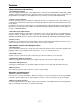
Controls and their functions Front panel (4) (6) (3) (1) (2) (5) POWER ON EJECT OFF AUTO OFF SD CHANNEL CONDITION VIDEO HD INPUT CHECK AUDIO SERVO HOME (7) UNITY AUDIO MONITOR L R F1 F2 F3 F4 F5 F6 F7 REMOTE ASSEM INSERT VIDEO OUT IN AUDIO OUT F13 IN F12 TC/CHR F11 7 8 9 FROM COPY F10 4 5 6 / BS 1 2 3 0 C T F ENT F9 (8) MULTI CUE SET UP TEST DIAG AUDIO LINE OUT UNITY /VAR ADJUST SHTL JOG VAR F8 REC INHIBIT HEADPHONES (9) LEVEL CURSOR EXECUT
Controls and their functions Front panel (14)(15) (16) (17) POWER ON EJECT OFF AUTO OFF SD CHANNEL CONDITION VIDEO HD INPUT CHECK AUDIO SERVO HOME 1 23 4 AUDIO MONITOR R L F1 F2 F3 F4 F5 F6 F7 REMOTE ASSEM INSERT AUDIO F13 IN OUT IN OUT F12 TC/CHR SET UP TEST DIAG F11 7 8 9 FROM COPY F10 4 5 6 / BS 1 2 3 0 C T F ENT F9 UNITY MULTI CUE VIDEO AUDIO LINE OUT UNITY /VAR ADJUST SHTL JOG VAR F8 REC INHIBIT HEADPHONES (13) 1 LEVEL CURSOR EXECUTE
Controls and their functions (19) Front panel (20) POWER ON EJECT OFF AUTO OFF SD CHANNEL CONDITION VIDEO HD INPUT CHECK AUDIO SERVO HOME MULTI CUE VIDEO UNITY AUDIO MONITOR L R F1 F2 F3 F4 F5 F6 F7 AUDIO F13 IN F12 TC/CHR F11 7 8 9 FROM COPY F10 4 5 6 / BS 1 2 3 0 C T F ENT F9 REMOTE (21) (22) (23) (18) ASSEM INSERT OUT SET UP IN OUT TEST DIAG AUDIO LINE OUT UNITY /VAR ADJUST SHTL JOG VAR F8 REC INHIBIT HEADPHONES LEVEL CURSOR EXECUTE REVIE
Controls and their functions (24) (26) (25) (27) Front panel POWER ON EJECT OFF AUTO OFF SD CHANNEL CONDITION VIDEO HD INPUT CHECK AUDIO SERVO HOME MULTI CUE VIDEO UNITY AUDIO MONITOR R L F1 F2 F3 F4 F5 F6 F7 AUDIO F13 IN OUT IN OUT F12 TC/CHR SET UP TEST DIAG F11 7 8 9 FROM COPY F10 4 5 6 / BS 1 2 3 0 C T F ENT F9 (28) (29) (30) (31) REMOTE ASSEM INSERT AUDIO LINE OUT UNITY /VAR ADJUST SHTL JOG VAR F8 REC INHIBIT HEADPHONES LEVEL CURSOR EXEC
Controls and their functions Front panel POWER ON EJECT OFF AUTO OFF SD CHANNEL CONDITION VIDEO HD INPUT CHECK AUDIO SERVO HOME MULTI CUE VIDEO UNITY AUDIO MONITOR L R F1 F2 F3 F4 F5 F6 F7 AUDIO F13 IN OUT IN OUT F12 TC/CHR SET UP TEST DIAG F11 7 8 9 FROM COPY F10 4 5 6 / BS 1 2 3 0 C T F ENT F9 REMOTE ASSEM INSERT AUDIO LINE OUT UNITY /VAR ADJUST SHTL JOG VAR (36) (37) (38) F8 (39) REC INHIBIT HEADPHONES LEVEL CURSOR EXECUTE REVIEW PREVIEW
Controls and their functions Front panel POWER ON EJECT OFF AUTO OFF SD CHANNEL CONDITION VIDEO HD INPUT CHECK AUDIO SERVO HOME MULTI CUE VIDEO UNITY AUDIO MONITOR L R F1 F2 F3 F4 F5 F6 F7 AUDIO F13 IN OUT IN OUT F12 TC/CHR SET UP TEST DIAG F11 7 8 9 FROM COPY F10 4 5 6 / BS 1 2 3 0 C T F ENT F9 REMOTE ASSEM INSERT AUDIO LINE OUT UNITY /VAR ADJUST SHTL JOG VAR F8 REC INHIBIT HEADPHONES LEVEL CURSOR EXECUTE REVIEW PREVIEW PREROLL ENTRY REW S
Controls and their functions Connector section (1) (2) ~AC IN FUSE 125V 5A (12) (11) REF IN (7) (4) (5) (8) (9) (6) VIDEO OUT SD 1 HD ON 2 WFM 3 SD SDI OUT1 IN (10) HD SDI IN OUT 1 OUT 3 ON 75Ω (SUPER) 75Ω OFF CH OFF 1 3 2 4 π CH CH INPUT π 5 7 6 8 π ACTIVE THROUGH CH ACTIVE THROUGH OUT2 π SD OUT 2 MONITOR (SUPER) HD SD CH 1 3 CH 2 4 π REF OUT CH OUTPUT π SPARE 5 7 CH 6 8 π MONITOR π (SUPER) DIGITAL AUDIO REMOTE OUT REMOTE IN REMOTE IN/OUT V/A CONTROL
Controls and their functions Connector section (15)(13)(14)(16)(17) (18) REF IN VIDEO OUT SD 1 HD ~AC IN FUSE 125V 5A ON 2 WFM 3 SD SDI IN OUT1 HD SDI IN OUT 1 OUT 3 ON 75Ω (SUPER) 75Ω OFF CH OFF 1 3 CH 2 4 π CH INPUT π ACTIVE THROUGH 5 7 CH 6 8 π ACTIVE THROUGH OUT2 π SD OUT 2 MONITOR (SUPER) HD SD CH 1 3 CH 2 4 π REF OUT CH OUTPUT π SPARE 5 7 CH 6 8 π MONITOR π (SUPER) DIGITAL AUDIO REMOTE OUT REMOTE IN REMOTE IN/OUT V/A CONTROL CONTROL PANEL AUDIO IN PUS
Controls and their functions Connector section (19) (20)(21)(24) REF IN VIDEO OUT SD 1 HD ~AC IN FUSE 125V 5A ON 2 WFM 3 SD SDI IN OUT1 HD SDI IN OUT 1 OUT 3 ON 75Ω (SUPER) 75Ω OFF CH 1 3 CH 2 4 INPUT CH 5 7 CH 6 8 CH 1 3 CH 2 4 OUTPUT CH 5 7 CH 6 8 OFF π π π ACTIVE THROUGH ACTIVE THROUGH OUT2 π OUT 2 SD MONITOR (SUPER) HD SD π REF OUT π π SPARE MONITOR π (SUPER) DIGITAL AUDIO REMOTE IN REMOTE OUT REMOTE IN/OUT V/A CONTROL CONTROL PANEL AUDIO IN PUSHCH
Controls and their functions Connector section (26) (27) (28) REF IN VIDEO OUT SD 1 HD ~AC IN FUSE 125V 5A (29) ON 2 WFM 3 (30) SD SDI OUT1 IN HD SDI IN OUT 1 OUT 3 ON 75Ω (SUPER) 75Ω OFF CH 1 3 CH 2 4 INPUT CH 5 7 CH 6 8 CH 1 3 CH 2 4 OUTPUT CH 5 7 CH 6 8 OFF π π π ACTIVE THROUGH ACTIVE THROUGH OUT2 π OUT 2 SD MONITOR (SUPER) HD SD π REF OUT π π SPARE MONITOR π (SUPER) DIGITAL AUDIO REMOTE IN REMOTE OUT REMOTE IN/OUT V/A CONTROL RS-232C PARALLEL IN/O
Connections Connection for a single unit Press the REMOTE button on the front panel to turn the lamp (LOCAL) off.
Connections Connection for 2 units Source side Recorder side Press the REMOTE button at the front panel to light the lamp (REMOTE). Press the REMOTE button at the front panel to extinguish the lamp (LOCAL). When performing automatic editing with RS-422A, press the F1 (P-2) key at the SET UP INTERFACE menu to switch.
Connections Connection with an editing controller Recorder POWER AV monitor ON Video monitor signal EJECT OFF AUTO OFF SD CHANNEL CONDITION VIDEO HD INPUT CHECK AUDIO SERVO HOME MULTI CUE ASSEM INSERT VIDEO Audio monitor signal UNITY AUDIO MONITOR R L LEVEL CURSOR IN F12 TC/CHR F11 7 8 9 FROM COPY F10 4 5 6 / BS 1 2 3 C T F ENT 0 F1 F2 F3 F4 F5 F6 F7 AUDIO F13 F9 REMOTE OUT SET UP IN OUT TEST DIAG AUDIO LINE OUT UNITY /VAR ADJUST SHTL JOG VAR F8
Tapes There are two tape types: M and L. M-cassettes: 57 minutes (576/50i), 63 minutes (1080/59.94i, 720/59.94p and 480/59i), 75 minutes (1080/25p and 1080/50i), 79 minutes (1080/23.98 and 1080/24p) L-cassettes: 112 minutes (576/50i), 124 minutes (1080/59.94i, 720/59.94p and 480/59i), 149 minutes (1080/25p and 1080/50i), 155 minutes (1080/23.98p and 1080/24p) Align the cassette with the marks on the unit’s insertion slot and push it in gently. The cassette tape will be loaded automatically.
Recording Preparation ∑ Release the recording inhibit mode ≥Confirm that the REC INHIBIT lamp has gone out. REC INHIBIT If the lamp has not gone out, set the positions of the cassette’s accidental erasure prevention pins and the F13 (REC INH) setting on the HOME menu to the recording enabled status. ∑ Selecting the input signals and adjusting their levels ≥Select the video input signal (INT SG or DIGITAL) on the VIDEO IN menu.
Recording Preparation ∑ Setting the time code ≥Press the F4 (TC/CTL) key on the HOME menu to select TC. ≥Select the internal or external time code on the TC/CHR menu and set the generating mode. Operation (1) Press the PLAY button while pressing the REC/EDIT button. Recording will start. PLAY REC/EDIT (2) Recording stops when the STOP button is pressed.
Recording Simultaneous playback monitoring ∑ Video monitoring ≥Set VIDEO during recording to TAPE on the VIDEO OUT HD SET UP STATE menu. REC TAPE VIDEO ∑ Audio monitoring ≥Set AUDIO during recording to TAPE on the AUDIO OUT SET UP STATE menu. VIDEO REC TAPE D. AUDIO TAPE ≥The digital audio and the digital video signals are interlinked at all times. They can not be set separately. ≥Simultaneous playback of the analog cue signal is not possible.
Recording This flowchart shows the steps for recording the digital signals which are supplied to the unit from an external digital device. 11. Check the connections. 12. Turn on the power. 13. After making sure that no cassette tape is inserted in this unit, set the system frequency 59.94, 23.98, 24, 25 or 50 by F1 (FREQ) key of the SYSTEM SET UP menu. F13 F12 F11 F10 F9 F1 F2 F3 F4 F5 F6 F7 F8 The frequency setting is possible when the F1 key is pressed.
Recording 14. Insert a recording-enabled cassette. It should be borne in mind that the 4-channel or 8-channel audio version will be identified in accordance with the position selected for the cassette C bit pin, as mentioned on page 25. Note that when the cassette tape is inserted, it is not possible to change the system frequency which was set using the F1 (FREQ) key on the SYSTEM SET UP menu of the previous page. 15. Press the F13 (REC INH) key on the HOME menu to set to “FREE”. REC INH FREE 16.
Recording ≥ The REF synchronization specifications applying when the 1080/23p, 24p or 25p True-P (Non-PsF) system format is selected are the same specifications as for the PsF system format. Use an interlace format signal for the HD tri-level SYNC signal. ≥ The True-P (Non-PsF) input/output interface does not support EMBEDDED AUDIO/TC/VANC. ≥ The enhance and filter response picture quality adjustments do not work for True-P (Non-PsF) outputs.
Playback Operation PLAY (1) Press the PLAY button. Playback will start. (2) Playback stops when the STOP button is pressed. If the JOG, SHTL, VAR, FF, or REW button is pressed in place of the STOP button, operation is directly transferred to the mode that corresponds to the respective button. ∑ Monitoring the audio signals ≥Select the audio channel for output from the AUDIO MONITOR L/R connector or the HEADPHONES jack using the L/R buttons.
Basic operations ∑ Stop Press the STOP button. The tape will stop. ≥In order to protect the tape, the tape tension is automatically released (a process called “loosening”) when the time selected by the F12 (STILL) key on the HOME SET UP menu has elapsed. The READY lamp will flash. ≥Furthermore, the READY OFF mode is automatically established when the time selected by the F13 (STBY OFF) key on the HOME SET UP menu has elapsed. The READY lamp will go out and the STOP lamp will light.
Basic operations ∑ Shuttle (SHTL) SHTL (1) The unit is placed in the shuttle mode when the SHTL button is pressed and the lamp lights. (2) Turn the search dial. ≥The tape speed changes depending on the angle by which the dial is turned. ≥The tape speed is displayed on the search indicator. ≥The tape speed can be varied up to a maximum of n 50 times the normal tape speed. ≥The maximum speed can be set by pressing the F6 (SHTL MAX SP) key on the PANEL SET UP menu.
Basic operations ∑ Variable (VAR) The variable mode is a low-speed version of the shuttle mode. This operation may be initiated from STOP or PLAY mode or during normal recording. VAR (1) The unit is placed in the variable mode when the VAR button is pressed and the lamp lights. (2) Turn the search dial. ≥The tape speed changes depending on the angle by which the dial is turned, and it is displayed on the search indicator.
Basic operations ∑ Tape speed override (TSO) function This is a function for finely adjusting the normal playback speed in the range of n15%. PLAY (1) Press the PLAY button. Normal playback starts. (2) Turn the search dial while pressing the PLAY button, or press the i or j keys. When using the search dial, the tape speed changes depending on the angle to which the search dial is turned. When using the i or j keys, the tape speed changes according to how long the key is pressed continously.
Basic operations When TC INPUT is set to the REVERSE mode* (1) Press the cursor center key to display the cursor. The time code value will be highlighted. Cursor center key LTCR 00 : 00 : 00 : 00 Cursor key Cursor (2) Move the cursor with the cursor key (4) to the CUE TIME display section. The cue display section will be highlighted. CUE TIME H M S F Cursor (3) Press the cursor center key again to change it to a bar cursor. Enter the cue point with the number keys.
Basic operations ∑ Correction of the cue point When TC INPUT is set to the STANDARD mode (1) Move the cursor to the place which is to be corrected. CUE TIME 00 H 41 M 07 S 04 F Cursor (2) ENTER the new value with the number keys. CUE TIME 00 H 44 M 07 S 04 F (3) Press the ENT key. ≥Cue points cannot be cleared. When TC INPUT is set to the REVERSE mode Partial corrections cannot be made for cue points.
Manual editing Manual editing is a method used for editing which does not involve the REGISTRATION of edit points (IN/OUT points). 1. Check the connections. 2. Switch on the power. 3. Insert the cassette to be edited. 4. Press the F13 (REC INH) key on the HOME menu to set to FREE or NRML.REC. REC INH FREE 5. Select and adjust the input signals. 6. To record the time code, perform the time code-related settings on the TC/CHR menu. 7.
Manual editing 12. Search the edit start (IN) point and set the picture to the still mode. 13. Press-the PREROLL button if preroll is required. 14. Provide input of the editing source. 15. Press the PLAY button to place the unit into playback mode. 16. Press the REC/EDIT button at the edit start (IN) point. Editing will start. 17. To end editing, press the STOP or the REC/EDIT button.
Manual audio cross editing Below is a flowchart showing the steps taken for editing in which audio signals are cross-faded (while the preceding playback sound is being faded out, the player sound is faded in) in the manual edit mode. 1. Prepare for manual editing by referring to steps 1 to 14 in the manual editing flowchart. 2. Set the F13 (MODE) key on the INSERT (OR ASSEMBLE) MANUAL EDIT SET UP menu to XFADE. MODE X FADE 3.
Automatic insert/assemble editing The following flowchart shows the operation for automatic insert editing or automatic assemble editing with two digital VTRs. 1. Check the connections. 2. Switch on the power to the player and to the recorder. 3. Insert the cassettes required for editing into the VTRs. 4. Press the REMOTE button on the player and set the button to REMOTE (lamp is lit). REMOTE 5. Press the REMOTE button on the recorder and set the button to LOCAL (lamp is not lit). REMOTE 6.
Automatic insert/assemble editing 12. Press the INSERT or the ASSEM button to display the INSERT (or the ASSEMBLE) EDIT menu, and then press the F12 key to set to AUTO EDIT. When the F9 (INSERT/ASSEMBLE) key is highlighted, the editing mode is established. 13. When insert editing was selected in step 12 by pressing the INSERT button, press the F13 (CH SELECT) key on the INSERT AUTO EDIT menu, and select the channels to be edited on the editing channel selection menu. 14.
Audio split editing The following flowchart shows the operation for separately entering the audio and video edit point positions for automatic editing. 1. Press the INSERT button to display the INSERT AUTO EDIT menu. INSERT 2. Press the F10 (SPLIT) key on the INSERT AUTO EDIT menu to set it to be highlighted. 3. Refer to the flowchart for automatic insert editing operation, and register the video edit points. 4. Register the audio edit points. F13 F12 F11 F10 F9 F1 F2 F3 F4 F5 F6 F7 F8 5.
Audio split editing OUT point preview ∫ Previewing the automatic insert editing OUT point (when audio split is OFF) This flowchart shows the operation to preview the automatic insert editing OUT point. The OUT point for automatic assemble editing can not be previewed. 1. Press the INSERT button to display the INSERT AUTO EDIT menu. 2. Use the automatic insert editing flowchart as a reference and register the VIDEO OUT point. 3.
Variable memory Function 1. Set the F3 (W/PLYR) key to OFF. W/PLYR OFF 2. Set the F4 (VAR MEMO) key to ON. VAR MEMO ON ≥If the IN and OUT points have already been entered, they will be automatically cleared. ≥If the split mode is ON, it will be forcibly turned off. ≥When the variable memory function is used, the AUDIO IN and OUT points cannot be entered. 3. Input the unit’s edit IN point. The variable memory playback will start at this point.
Variable memory function By operating the VTR search dial which is connected to the unit’s RS-422A REMOTE OUT or REMOTE IN/OUT connector, the playback speeds and directions can be stored in the memory, after which the stored contents can be regenerated during automatic editing and stored in the memory of the unit (recorder). 1. Set the F3 (W/PLYR) key to ON.
Connector signals ∑ VIDEO IN HD SDI (DIGITAL) BNCk2, active through SD SDI IN (DIGITAL) BNCk2, active through SD SDI SPARE BNCk1 HD REF IN BNCk2, loop-through with 75≠ termination switch SD REF IN BNCk2, loop-through with 75≠ termination switch ∑ VIDEO OUT HD SDI OUT (DIGITAL) BNCk3 HD SDI MONITOR OUT (DIGITAL) (SUPER) BNCk1 SD SDI OUT (DIGITAL) BNCk2 SD SDI MONITOR (DIGITAL) (SUPER) BNCk1 VIDEO OUT (ANALOG) BNCk3 HD REF OUT BNCk1 SD REF OUT BNCk1 WFM BNCk1, Waveform output, 75≠.
Connector signals ∑ PARALLEL I/O (50P) connector (1) PULSE SIGNAL: The signal fall is detected and the signal becomes active. Pin no. Signal Direction Type Description 1 REC COMMAND INPUT PULSE SIGNAL When this signal becomes active simultaneously with the play command, it transfers the VTR to the REC PLAY mode. However, the VTR is not transferred to the REC mode if the insert or assemble mode has been set. 2 PLAY COMMAND INPUT PULSE SIGNAL This transfers the VTR to the PLAY mode.
Connector signals Pin no. Signal Direction Type Description 16 TC_SOURCE_ EXT COMMAND INPUT PULSE SIGNAL This sets TC SOURCE to EXT and TC SLAVE to ON. 17 TC_SLAVE_AUTO COMMAND INPUT PULSE SIGNAL This sets TC SOURCE to INT and TC SLAVE to AUTO. During normal recording, the TCG value is recorded. During editing, the signal is regenerated at TC on the tape. 18 TL_SLAVE_MUST COMMAND INPUT PULSE SIGNAL This sets TC SOURCE to INT and TC SLAVE to SLAVE.
Connector signals Pin no. Signal Direction Type Description 29 FF STATUS OUTPUT ACTIVE_L This becomes active when the VTR is in the FF mode. 30 REW STATUS OUTPUT ACTIVE_L This becomes active when the VTR is in the REW mode. 31 STOP STATUS OUTPUT ACTIVE_L This becomes active when the VTR is in the STOP mode. 32 RE-422 REMOTE OUTPUT ACTIVE_L ON STATUS This becomes active when the RS-422 REMOTE status is ON.
Connector signals ∑ RS-422A REMOTE Pin No. Signal 1 FRAME GROUND 2 REM IN (j) 3 REM OUT (j) 4 GND 5 Pin No. Signal 6 GND LINE(j) 7 REM IN (j) STATUS LINE (i) 8 REM OUT (j) 9 FRAME GROUND CMD LINE (j) STATUS LINE (i) –––––– ∑ RS-232C REMOTE Pin No. Signal Pin No.
Video head cleaning Although this unit comes with an auto head cleaning function which reduces the amount of dirt on the heads, it is recommended that the video heads be cleanid every day for even more dependable operation. (For further details, please consult with your local dealer.) ∑ Operation Remove the cover of the upper portion on the cylinder.
Rack-mounting The VTR can be installed in a 19-inch standard rack using the AJ-MA37P rack-mounting adapters (optional accessory). It is recommended that the slide rail (CC3001-99-0191) made by Chassis Trak be used as the installed rails. For further details, consult your dealer. 1. Attach the inner members on each side of the VTR using the four screws supplied with the slide rails . The length of the screws used is limited.
Troubleshooting Symptom Cause and countermeasure VTR fails to operate as per the mode selected on the menu screen. Has the mode been changed on another menu? ≥The mode selected last has priority. ≥REC INHIBIT takes priority in the following sequence: CASSETTE, HOME and MANUAL/AUTO EDIT SET UP. Therefore, signals cannot be recorded if the REC INHIBIT status has been established on the cassette tape itself. VTR fails to operate even when a function button is pressed.
DIP switch AV microcomputer DIP switch specifications SW6501 ON (0) OFF (1) Remarks 1 Normal Not used 2 Normal Not used 3 Normal Not used 4 Normal Not used 5 Normal —— Keep this switch at the factory setting. 6 Normal —— Keep this switch at the factory setting. 7 —— Normal Keep this switch at the factory setting. Normal Keep this switch at the factory setting. 8 SYSCON microcomputer DIP switch specifications SW6071 1 ON OFF Normal Remarks Keep it at the factory setting.
Specifications Power supply AJ-HD3700BP: AC 120V, 50–60 Hz AJ-HD3700BE: AC 220–240V, 50–60 Hz Power consumption: 260W 1 indicates safety information.
Specifications Video system Sampling frequency/ quantizing Video compression system (with HD) Video compression rate (with HD) Error correction Data rates Samples t active lines (HD) SD video format HD: Y: 74.176 MHz; PB/PR: 37.088 MHz/10 bits SD: Y: 13.5 MHz; PB/PR: 6.75 MHz/10 bits Intra-Field DCT i VLC 1/4 Reed-Solomon product code 323 Mbps (1080/59.94i/8CH, 720/59.94p/8CH, 480/59.94i/8CH 319 Mbps (576/50i/8CH) 300 Mbps (1080/59.94i/4CH, 720/59.94p/4CH, 480/59.94i/4CH) 258 Mbps (1080/23.
Specifications Composite video output Y gain Composite video output PB/PR gain Composite video output setup Composite video output system phase Composite video output SYS SC phase j¶–i3 dB (synchronized to SD SDI) j¶–i3 dB (synchronized to SD SDI) n14 IRE (synchronized to SD SDI) n0.5 H more than n180 ° Audio Sampling frequency Quantizing Frequency response Dynamic range Distortion Crosstalk Wow & flutter Headroom 48 kHz (synchronized to video) 1080/23.
Specifications Audio adjustment ranges Audio input gain Audio output gain Monitor output gain Headphone output gain j¶–i12 dB j¶–i12 dB j¶–i12 dB (when coupled to headphone control) j¶–i12 dB Other input/output signals Time code input Time code output RS-422A input RS-422A output RS-422A input/output RS-232C Parallel input/output V/A control Control panel 2.4 V n1.4 V [p-p], 10 k≠, balanced (XLR k 1) 2.0 V n0.
– 57 –
PANASONIC BROADCAST & TELEVISION SYSTEMS COMPANY UNIT COMPANY OF MATSUSHITA ELECTRIC CORPORATION OF AMERICA Executive Office: One Panasonic Way 4E-7, Secaucus, NJ 07094 (201) 348-7000 EASTERN ZONE: One Panasonic Way 4E-7, Secaucus, NJ 07094 (201) 348-7621 Southeast Region: 1225 Northbrook Parkway, Ste 1-160, Suwanee, GA 30024 (770) 338-6835 Central Region: 1707 N Randall Road E1-C-1, Elgin, IL 60123 (847) 468-5200 WESTERN ZONE: 3330 Cahuenga Blvd W.