
User Manual


27
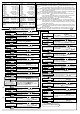
DI (Digital input)
DI (Digital input) has 3 functions.
• SV1/SV2 external selection function
SV1 or SV2 can be switched by external contact. However, this function is not available if Program
control function is selected during OUT/OFF key function selection.
DI terminals between 10 and 12 Open: SV1
DI terminals between 10 and 12 Closed: SV2
• OUT/OFF (RUN/STOP) external selection function
Control output OUT/OFF (Fixed value control) or Program control RUN/STOP can be switched.
[Fixed value control]
DI terminals between 10 and 12 Open : OUT (Control allowed)
DI terminals between 10 and 12 Closed: OFF (Control prohibited, control output OFF)
[Program control]
Program control RUN/STOP can be switched if the following operation is conducted during program
control standby.
Between DI terminals from Open to Closed: RUN (program control run)
Between DI terminals from Closed to Open: STOP (program control stop)
If DI terminal contact is changed from Closed to Open while pattern end output is turned on after
program control ended, pattern end output is turned off.
Circuit current when closed: 6mA
• Timer function
Timer counting starts by the external contact, and after the set delay time has elapsed, the selected
event output is turned on.
Program control function
If program control function is selected during OUT/OFF key function selection, 1 pattern 9 steps
program control can be performed.
To start program control, press the
key during program control standby.
(To stop the program control, press the
key for approx. 1 second again.)
Progressing time error: Within
1 minute
Pattern end output: Pattern end output can be selected by keypad.
Converter function
If Converter function is selected during Controller/Converter function selection, the following control
parameters are automatically set, and the controller can be used as a converter. (However, available
only for DC current output type). Input/output response is approx. 1 second.
SV1 (main set value): Scaling low limit value, OUT1 (Heating) integral time: 0, OUT1 (Heating)
derivative time: 0, OUT1 (Heating) proportional band: 100.0%, Manual reset: 0.0, A1 value: 0,
A2 value: 0, Direct/Reverse action: Direct action
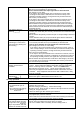
Attached functions
[Set value lock] Locks set values to prevent setting errors.
[Sensor correction] The PV is corrected when the temperatures in the controlled location differs from
those of the sensor location.
[PV filter] Reduces the effect of noise by putting first order
lag filter in the PV.
[Power failure countermeasure] The setting data is backed up in the non-volatile IC memory.
[Self-diagnosis] The CPU is monitored by a watchdog timer, and when an abnormal status is found
on the CPU, the controller is switched to warm-up status.
[Automatic cold junction temperature compensation] (Only thermocouple input type)
This detects the temperature at the connecting terminal between the thermocouple and the instrument,
and always maintains the same status as when the reference junction is located at 0
(32 ).
[Burnout]
When the thermocouple or RTD input is burnt out, OUT1 and EV1/OUT2 (Heating/Cooling control option) are
turned off [for DC current output type, OUT1 (Heating) low limit value], and PV/SV display flashes “
”.
[Warm-up indication]: After the power supply to the instrument is turned on, the sensor input
characters and temperature unit are indicated on the PV/SV display for approx. 3 seconds.
[Temporary PV/SV indication] If the Increase key is pressed during the PV/SV display mode, then the
opposite value to the value selected during PV/SV indication selection is indicated temporarily.
The value automatically reverts to the previous value in 2 seconds.
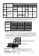
Standby mode
DI ON
Contact Closed
Contact Open
Standby mode
DI OFF
Contact Open
Program control STOP
Program control is performed
when the contact is changed
from Open to Closed.
Program control stops when
the contact is changed from
Closed to Open.
Controller
status
Contact Open
Stops program control.
Program control RUN
Contact Closed
Performs program control.