
User Manual

16
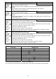
6.7 Auxiliary function setting mode
To enter the Auxiliary function setting mode, press
key for approximately 3 seconds while pressing
key in the PV/SV display mode.
To set or select each setting item, use
or key, then register the value with key.
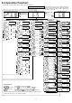
Setting item numbers such as [17], [18], etc. are the same as those on the “6.4 Operation flowchart” (p.12).
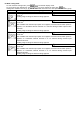
Character Name, Function, Setting range Default value
Set value lock selection
Unlock
[17]
• Locks the set values to prevent setting errors.
The setting item to be locked depends on the designation.
If Lock 1 or Lock 2 is selected, PID Auto- tuning and Auto-reset cannot be carried out.
•
(Unlock) : All set values can be changed.
(Lock 1): None of the set values can be changed.
(Lock 2): Only main setting mode can be changed.
(Lock 3): All set values can be changed. However, changed values revert to their
previous value after power is turned off because they are not saved in the
non-volatile memory. (If the value set by the communication function is the same
as the value before the setting, the value will not be written in the non-volatile
memory.)
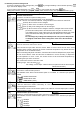
Do not change any setting item in Setup mode. If any item in Setup mode
is changed, it will affect other setting items such as the SV and Alarm
value.
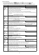
Sensor correction setting
0.0
[18]
• Sets the correction value for the sensor.
This corrects the input value from the sensor. When a sensor cannot be set at the exact
location where control is desired, the sensor measured temperature may deviate from the
temperature in the controlled location.
When controlling with plural controllers, sometimes the measured temperatures (input value)
do not concur with the same set value due to difference in sensor accuracy or dispersion
of load capacities. In such a case, the control can be set at the desired temperature by
adjusting the input value of sensors.
PV= Current PV+ Sensor correction value
• Setting range: -100.0 to 100.0
( ),
DC voltage, current input: -1000 to 1000 (The placement of the decimal point
follows the selection.)
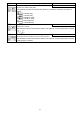
Communication protocol selection
Modbus ASCII mode
[19]
• Selects the communication protocol.
Not available if the Serial communication option is not added, or if Contact input option is
added.
•
: Modbus ASCII mode
: Modbus RTU mode
: MEWTOCOL (slave)
Instrument number setting
1
[20]
• Sets the instrument number individually to each instrument when communicating by
connecting plural instruments.
Not available if Serial communication option is not added or if Contact input option is added.
• Setting range: 1 to 99
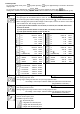
Communication speed selection
9600bps
[21]
• Selects a communication speed equal to that of the host computer.
Not available if Serial communication option is not added or if the Contact input option is
added.
•
: 2400bps
: 4800bps
: 9600bps
: 19200bps