
Information

(Bottom side)
6
5
4
3
2
1
13121110
9
8
7
2
6543
1
654
3
2
1
654
3
2
1
5
4
3
2
1
3
7
2
1
8
6
5
4
M
°C
19
19
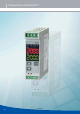
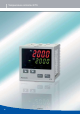
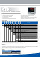
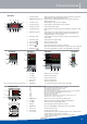
Parts and functions
Note: Color selection is the same for each size.
KT4 Series
KT2 Series
KT4H/4B Series
KT8 Series
KT9 Series
KT7 Series
1 PV/SV display (red): Indicates the input value and setting value. During setting mode, characters and
setting value of the setting item are indicated in turn.
2 MEMO/STEP display (green): Indicates memory number during fixed value control. Indicates step number
during program control.
3 PV indicator (red): Lights up when the input value (PV) is indicated.
4 SV indicator (green): Lights up when the main setting value (SV) is indicated.
5 AT indicator (yellow): Flashes during AT (auto-tuning).
6 T/R indicator (yellow): Flashes during serial communication (lit while sending data, unlit while receiving
data).
7 OUT indicator (green): Lights up when control output or OUT1 (heating side, option heating/cooling
control) is ON: For DC current output type, it flashes corresponding to the
manipulated variable in a 0.25 second cycle.
8 EV1 indicator (red): Lights up when event output 1 or OUT2 (cooling side, option heating/cooling
control) is ON.
9 EV2 indicator (red): Lights up when event output 2 is ON.
10 Increase key (
△
): Increases the numeric value.
11 Decrease key (
▽
): Decreases the numeric value.
12 Mode key (
MODE
): Selects the setting mode or registers the setting value.
(By pressing the Mode key, the setting value or selected value can be registered.)
13 OUT/OFF key (
OUT
OFF
): The control output OUT/OFF or program control RUN/STOP can be switched.
1 PV display: Indicates PV (process variable)
2 SV display: Indicates SV (setting value)
3 Increase key: Increases numerical value
4 Decrease key: Decreases numerical value
5 Mode key: Switches the setting mode
6 OUT/OFF key: Control output is turned on or off when control output is ON.
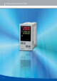
1 Action indicators (backlight: orange)
*F*C
T/R
AT
OUT1
OUT2
EVT1
EVT2
LOCK
Lights respectively when temperature unit *F/*C is selected
Lights during serial communication (option) TX output.
Flashes during auto-tuning or auto-reset
Lights when control output is ON or Heating output (option) is ON. For DC current ouptut type, it
flashes corresponding to the manipulated variable in 0.25 second cycles
Lights when cooling output (option) is ON.
Lights when alarm 1 output is ON.
Lights when alarm 2 output (option) is ON or heater burn-out alarm (option) is ON.
Lights when lock 1, Lock 2 or lock 3 is selected.
2 MEMO display Indicates the set value memory number (backlight: green).
3 PV display Indicates the PV (process variable) (backlight: red/orange/green).
4 SV display Indicates the SV (set value) (backlight: green).
5 Mode key Selects the setting mode and registers the set value.
6 OUT/OFF key The control output ON/OFF or auto/manual control can be switched.
7 Increase key Increases the numeric value.
8 Decrease key Decreases the numeric value.
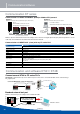
9 Tool connector By connecting the tool cable, the following operations can be conducted from the
external computer using the exclusive tool software.
sReading and setting of SV, PID and various set values from external computer
sReading of PV and action status
sFunction change
15/06/2012