TEMPERATURE CONTROLLER KT9 INSTRUCTION MANUAL
Preface Thank you for the purchase of Temperature controller KT9. This manual contains instructions for the mounting, functions, operations and notes when operating the KT9. For model confirmation and unit specifications, please read this manual carefully before starting operation. To prevent accidents arising from the misuse of this controller, please ensure the operator receives this manual. Notes • This instrument should be used according to the specifications described in the manual.
1.
--- CONTENTS --1. Model number 1.1 Explanation of model number ---------------------------------------------------- 6 1.2 Rated input ---------------------------------------------------------------------------- 7 1.3 How to read the rated label ------------------------------------------------------- 7 2. Name and functions of the sections ------------------------------------ 8 3. Mounting to the control panel 3.1 Site selection ----------------------------------------------------------------------- 10 3.
--- CONTENTS --OUT1 high limit ---------------------------------------------------------------------- 23 OUT1 low limit ----------------------------------------------------------------------- 23 OUT1 ON/OFF action hysteresis ----------------------------------------------- 23 OUT2 action mode ----------------------------------------------------------------- 23 OUT2 high limit ---------------------------------------------------------------------- 24 OUT2 low limit ---------------------------------------------
1. Model number 1.
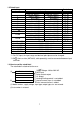
1.2 Rated input Input type K J R S B E T N PLC(W/Re5-26) Pt100 JPt100 Input range –200 to 1370 –199.9 to 400.0 –200 to 1000 0 to 1760 0 to 1760 0 to 1820 –200 to 800 –199.9 to 400.0 –200 to 1300 0 to 1390 0 to 2315 –199.9 to 850.0 –200 to 850 –199.9 to 500.0 –200 to 500 4 to 20mA DC 0 to 20mA DC 0 to 1V DC 0 to 10V DC 1 to 5V DC 0 to 5V DC –320 to 2500 –199.9 to 750.0 –320 to 1800 0 to 3200 0 to 3200 0 to 3300 –320 to 1500 –199.9 to 750.0 –320 to 2300 0 to 2500 0 to 4200 –199.9 to 999.
2. Name and functions of the sections (1) (2) (8) (3) (9) (4) (10) (5) (6) (11) (7) (14) (12) (15) (13) (Fig. 2-1) (1) PV display Indicates the PV (process variable) with a red LED. (2) SV display Indicates the SV (main set value) or MV (manipulated variable) with a green LED. (3) SV1 indicator The green LED lights when SV1 is selected. (4) SV2 indicator The green LED lights when SV2 is selected. (5) OUT1 indicator When OUT1 or Heating output is on, the green LED lights.
(8) AT indicator The yellow LED flashes during auto-tuning or auto-reset. (9) TX/RX indicator The yellow LED flashes during Serial communication. (10) A1 indicator When A1 output is on, the red LED lights. (11) A2/LA indicator When A2 output is on, the red LED lights. (12) Increase key: Increases the numeric value. (13) Decrease key: Decreases the numeric value. (14) Mode key: Selects the setting mode or registers the set value. (By pressing the Mode key, the set value or selected value can be registered.
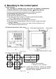
3. Mounting to the control panel 3.
3.4 CT (Current transformer) external dimensions (Unit: mm) AKT4815 (for 5A, 10A and 20A) (Fig. 3.4-1) 3.5 Mounting AKT4816 (for 50A) Notice As the case is made of resin, do not use excessive force while screwing in the mounting bracket, or the case or screw type mounting bracket could be damaged. The torque should be 0.12N•m. Mount the controller vertically to the flat, rigid panel to ensure it adheres to the Dust-proof/Drip-proof specification (IP66). Mounting panel thickness: 1 to 8mm.
4. Wiring Warning Turn the power supply to the instrument off before wiring or checking. Working or touching the terminal with the power switched on may result in severe injury or death due to Electric Shock. Moreover, the instrument must be grounded before the power supply to the instrument is turned on. 4.
Notice • The terminal block of KT9 series is designed to be wired from the left side. The lead wire must be inserted from the left side of the terminal, and fastened with the terminal screw. • Dotted lines show options. • If A2 (option) and Heater burnout alarm (option) are applied together, use terminals 12-13 for A2, and 9-10 for the Heater burnout alarm.
[Heater burnout alarm output] (1) This alarm is not available for detecting 15 heater current under phase control. 16 (2) This alarm is not available for detecting 3-phase heater current. CT input terminals Power source CT (3) Use the current transformer (CT) provided, and pass one lead wire of the heater circuit into the hole of the CT. (4) When wiring, keep CT wire away from any AC source and load wire to avoid external interference. Heater (Fig. 4.
5. Setup For the thermocouple and RTD input, the sensor input characters and temperature unit are indicated on the PV display and the input range high limit value is indicated on the SV display for approx. 3 seconds after the power is turned on. See (Table 5-1). For DC input, the sensor input characters are indicated on the PV display and the scaling high limit value is indicated on the SV display. See (Table 5-1).
5.1 Operation flow chart Alarm 1 (A1) setting procedure [Numbers (1) to (5) are indicated on the flow chart.] (1) [A1 type]: Select an alarm type [If an alarm type except for is selected, items (2) to (5) are indicated and they can be set if necessary.] (2) [A1 action Energized/Deenergized]: Select Alarm 1 contact output ON (Energized: ) or OFF (Deenergized: ). (3) [A1 hysteresis]: Set A1 hysteresis. (4) [A1 action delayed timer]: Set A1 action delayed time.
Input type (character indication) and range Alarm type K High limit alarm: The alarm action is deviation setting from the SV. The alarm is activated if the input value reaches the high limit set value. Character indication: Low limit alarm: The alarm action is deviation setting to the SV. The alarm is activated if the input value goes under the low limit set value. Character indication: High/Low limits alarm: Combines High limit and Low limit alarm actions.
5.2 Main setting mode The main setting mode can be selected by pressing the key. The SV can be increased or decreased by pressing the or key. key, and the unit reverts to the PV/SV The SV is registered by pressing the display mode. Character Default value Name, Function, Setting range (PV display) (SV display) SV1 0 • Sets SV1. • Setting range: SV low limit to SV high limit, or scaling low limit value to scaling high limit value SV2 0 • Sets SV2. • Not available if Serial communication (option) is added.
[Auto-reset] • If auto-reset “Perform” is selected and the key is pressed, the AT indicator flashes and the unit reverts to the PV/SV display mode. • If auto-reset is performed, offset correction immediately starts. • To prevent key misoperation, other settings cannot be performed for 4 minutes after auto-reset starts. • After auto-reset is completed, the AT indicator is turned off and the reset value is automatically set. OUT1 proportional band setting 10 • Sets OUT1 proportional band.
A1 value setting 0 • Sets the action point for A1 output. Setting the value to 0 or 0.0 disables the function. (excluding Process high and Process low alarm) • Not available if No alarm action is selected during A1 type selection. • Setting range: See (Table 5.4-1). . and measured current value are displayed alternately. A2 value setting 0 • Sets the action point for A2 output. Setting the value to 0 or 0.0 disables the function.
Character (PV display) Name, Function, Setting range Default value (SV display) Unlock Set value lock selection • Locks the set value to prevent setting errors The setting item to be locked depends on the selection. • PID auto-tuning or auto-reset does not work if Lock 1 or Lock 2 is selected. • When selecting Lock, select Lock 1, Lock 2 or Lock 3 after setting the necessary items in the status Unlock. (Unlock): All set values are changeable. • (Lock 1): None of the set values can be changed.
Parity selection Even parity • Selects the parity. • Not available if Serial communication (option) is not added or if is selected during Communication protocol selection. • No parity: , Even parity: , Odd parity: Stop bit selection 1 • Selects the stop bit. • Not available if Serial communication (option) is not added or if is selected during Communication protocol selection. • Selecting item: (1) or (2) 5.
Scaling high limit setting 9999 • Sets scaling high limit value. • Available only for the DC input • Setting range: Scaling low limit value to input range high limit value (The placement of the decimal point follows the selection) Scaling low limit setting –1999 • Sets scaling low limit value.
OUT2 high limit setting 100% • Sets the high limit value of OUT2. • Not available if OUT2 is ON/OFF action or if Heating/Cooling control (option) is not applied • Setting range: OUT2 low limit value to 105% (Setting higher than 100% is effective to DC current output type.) OUT2 low limit setting 0% • Sets the low limit value of OUT2.
A2 type selection No alarm action • Selects A2 type. • Available only when A2 (option) is applied • The selecting item is the same as those of A1 type selection. A1 action Energized/Deenergized selection Energized • Selects A1 action Energized/Deenergized. • Not available if No alarm action is selected during A1 type selection • Selecting item Energized: Deenergized: A2 action Energized/Deenergized selection Energized • Selects A2 action Energized/Deenergized.
Direct/Reverse control action selection Reverse • Selects either Direct (Cooling) or Reverse (Heating) (Heating) action control action. • Selecting item Direct (Cooling): Reverse (Heating): AT bias setting 20 • Sets the bias value for performing PID auto-tuning. • Not available for DC input • Setting range: 0 to 50 (0 to 100 ) With a decimal point,0.0 to 50.0 (0.0 to 100.0 ) Setting item not used When Serial communication (option) is applied, this item appears. However, do not set this item.
Energized/Deenergized function [If the alarm action Energized is selected] When the alarm output indicator is lit, the alarm output (terminals 7-8 or 12-13) is conducted (ON). When the alarm output indicator is unlit, the alarm output is not conducted (OFF). See (Fig. 5.6-1). [If the alarm action Deenergized is selected] When the alarm output indicator is lit, the alarm output (terminals 7-8 or 12-13) is not conducted (OFF). When the alarm output indicator is unlit, the alarm output is conducted (ON).
6. Running After the controller is mounted to the control panel and wiring is completed, operate the unit following the procedures below. (1) Turn the power supply to the KT9 Series ON. For approx. 3 seconds after the power is switched ON, sensor input characters and temperature unit are indicated on the PV display, and the input range high limit value is indicated on the SV display. See (Table 6-1). For the DC input, for approx.
7. Action explanation 7.1 OUT1 action Heating (reverse) action Cooling (direct) action Proportional band Proportional band ON ON Control action OFF OFF SV setting Relay contact output SV setting H 4 H 4 H 4 H 4 H 4 H 4 C 5 C 5 C 5 C 5 C 5 C 5 L 6 L 6 L 6 L 6 L 6 L 6 Cycle action is performed according to deviation.
7.3 OUT1 ON/OFF action Heating (reverse) action Cooling (direct) action Hysteresis Hysteresis ON ON Control action OFF OFF SV setting Relay contact output Non-contact voltage output DC current output SV setting H 4 H 4 H 4 H 4 C 5 C 5 C 5 C 5 L 6 L 6 L 6 L 6 + 5 + 5 + 5 12V DC 0V DC + 5 0V DC 12V DC 6 6 6 6 + 5 + 5 + 5 + 5 20mA DC 4mA DC 4mA DC 6 6 6 20mA DC 6 Indicator (OUT1) Green Lit Unlit : Acts ON (lit) or OFF (unlit).
7.4 OUT2 (Heating/Cooling control) action (option) Heating P-band (Cooling P-band) ON ON Control action Heaing action (Cooling action) OFF OFF SV setting Relay contact output (OUT1) H 4 H 4 H 4 C 5 C 5 C 5 L 6 L 6 L 6 Cycle action is performed according to deviation. Relay contact output (OUT2) 9 9 9 10 10 10 Cycle action is performed according to deviation.
7.5 OUT2 (Heating/Cooling control) action (when setting Dead band) Heating P-band Dead band (Cooling P-band) ON ON Heatng action Control action (Cooling action) OFF OFF SV setting Relay contact output (OUT1) H 4 H 4 H 4 C 5 C 5 C 5 L 6 L 6 L 6 Cycle action is performed according to deviation. Relay contact output (OUT2) 9 9 9 10 10 10 Cycle action is performed according to deviation.
7.6 OUT2 (Heating/Cooling control) action (when setting Overlap band) Heating P-band Cooling P-band Overlap band ON Control action ON Heating action (Cooling action) OFF OFF SV setting Relay contact output (OUT1) H 4 H 4 H 4 C 5 C 5 C 5 L 6 L 6 L 6 Cycle action is performed according to deviation. Relay contact output (OUT2) 9 9 9 10 10 10 Cycle action is performed according to deviation.
7.
7.8 SV1/SV2 external selection action SV1 SV1/SV2 external selection Indicator Green SV2 14 14 17 17 SV1 Lit SV2 Unlit SV1 Unlit SV2 Lit 8. Control action explanations 8.1 PID (1) Proportional band (P) Proportional action is the action during which the control output varies in proportion to the deviation between the SV and the PV (processing temperature).
(B) In the case of a stable control The AT process will fluctuate around the SV. (1) Calculating PID constant (2) PID constant calculated (3) Controlled by the PID constant set by auto-tuning SV Temperature Time AT starting point (1) (3) (2) (Fig. 8.2-2) (C) In the case of a large difference between the SV and processing temperature as the temperature is falling When AT bias is set to 20 , the AT process will fluctuate at the temperature 20 higher than the SV.
9. Specifications 9.1 Standard specifications Mounting : Flush Setting : Membrane sheet key Display PV display : Red LED 4 digits, character size, 18 x 8 (H x W)mm SV display : Green LED 4 digits, character size, 13.2 x 6 (H x W)mm Accuracy (Setting, indication) Thermocouple : Within 0.2% of each input span 1digit or within 2 (4 ), whichever is greater However, for R, S input, 0 to 200 (0 to 400 ): Within 6 (12 ) B input, 0 to 300 (0 to 600 ): Accuracy is not guaranteed.
Input Thermocouple RTD DC current DC voltage : K, J, R, S, B, E, T, N, PL- , C (W/Re5-26) External resistance, 100 or less, however, for B, 40 or less : Pt100, JPt100, 3-wire system Allowable input lead wire resistance, 10 or less per wire : 0 to 20mA DC, 4 to 20mA DC Input impedance, 50 [50 shunt resistor (AKT4810, sold separately) must be connected between input terminals] Allowable input current 50mA or less [If 50 shunt resistor (AKT4810, sold separately) is used] : 0 to 1V DC Input impedance, 1M or
• ON/OFF action: When OUT1 proportional band is set to 0 OUT1 proportional band (P) Thermocouple: 0 to 1000 (0 to 2000 ) RTD: 0.0 to 999.9 (0.0 to 999.9 ) DC current, voltage: 0.0 to 100.0% (ON/OFF action when set to 0 ( ), 0.0 ( ) or 0.0%) Integral time (I) : 0 to 1000sec (Off when set to 0) Derivative time (D) : 0 to 300sec (Off when set to 0) OUT1 proportional cycle : 1 to 120sec (Not available for DC current output type) ARW : 0 to 100% OUT1 hysteresis : Thermocouple, RTD input: 0.1 to 100.
Dielectric strength Between input terminal and ground terminal, 1.5kV AC for 1 minute Between input terminal and power terminal, 1.5kV AC for 1 minute Between output terminal and ground terminal, 1.5kV AC for 1 minute Between output terminal and power terminal, 1.5kV AC for 1 minute Between power terminal and ground terminal, 1.5kV AC for 1 minute Weight : Approx. 370g External dimension: 96 x 96 x 98.
• DC input Indication range : [Scaling low limit value – Scaling span x 1%] to [Scaling high limit value + Scaling span x 10%] However, if the input value goes out of the range –1999 to 9999, the PV display flashes “ ” or “ ”. Control range : [Scaling low limit value – Scaling span x 1%] to [Scaling high limit value + Scaling span x 10%] • DC input disconnection: When DC input is disconnected, PV display flashes “ ” for 4 to 20mA DC and 1 to 5V DC inputs, and ” for 0 to 1V DC input.
Accessories included: Instruction manual 1 copy Screw type mounting brackets 1 set CT (current transformer) For rating 5A, 10A, 20A : AKT4815 1 piece For rating 50A : AKT4816 1 piece Accessories sold separately: Terminal cover (AKT9801) 1 piece 50 shunt resistor (AKT4810) 1 piece 9.2 Optional specifications Alarm 2 (A2) When A2 action is set as Energized, the alarm action point is set by deviation from OUT1 SV (except Process alarm).
OUT2 ON/OFF action hysteresis: Thermocouple, RTD input: 0.1 to 100.0 ( ) DC current, voltage input: 1 to 1000 (The placement of the decimal point follows the selection) Output Relay contact, 1a Control capacity, 3A 250V AC (resistive load) 1A 250V AC (inductive load cosø=0.
10.1 Indication Problem The PV display is indicating [ ]. [ ] is flashing on the PV display. [ ] is flashing on the PV display. Presumed cause and solution • Control output OFF function is working. Press the OUT/OFF key for approx. 1 second to release the function. • Burnout of thermocouple, RTD or disconnection of DC voltage (0 to 1V DC). Change each sensor.
Problem Presumed cause and solution • Check whether the input signal wire for DC voltage The value set during (0 to 5V DC, 0 to 10V DC) or DC current (0 to 20mA DC) the Scaling low limit is disconnected. setting remains on the How to check whether the input signal wire is disconnected PV display.
10.3 Control Problem Temperature does not rise. The control output remains ON status. The control output remains OFF status. Presumed cause and solution • The sensor is out of order. Replace the sensors. • Check whether the sensor is securely mounted to the instrument input terminal. Check whether control output terminals are securely mounted to the actuator input terminals. Mount the sensor or control output terminal securely. • Check whether the wiring of sensor or control output terminals is correct.
[Auxiliary function setting mode 1] Character Setting item Set value lock SV high limit SV low limit Sensor correction Communication protocol Instrument number Communication speed Parity Stop bit Default value Unlock 1370 –200 0.
If you have any inquiries, please consult our agency or the shop where you purchased the unit. Panasonic Electric Works Co., Ltd.