Feature Manual Hybrid IP-PBX KX-TDA50/KX-TDA100 Model No. KX-TDA200/KX-TDA600 Thank you for purchasing a Panasonic Hybrid IP-PBX. Please read this manual carefully before using this product and save this manual for future use. KX-TDA50: PSMPR Software File Version 5.0000 or later KX-TDA100/KX-TDA200: PMPR Software File Version 5.0000 or later KX-TDA600: PLMPR Software File Version 5.
Introduction Introduction About the Feature Manual The Feature Manual is designed to serve as an overall reference describing the features of the Panasonic Hybrid IP-PBX. It explains what the PBX can do, as well as how to obtain the most of its many features and facilities. The Feature Manual is divided into the following sections: Sections 1 to 20, Features and Configurations Describes the call handling, system configuration and administration features of the PBX.
Introduction Abbreviations There are many abbreviations used in this manual (e.g., "PT", for proprietary telephone). Please refer to the list in the next section for the meaning of each abbreviation. Note • • • • • The contents of this manual apply to PBXs with a certain software version, as indicated on the cover of this manual. To confirm the software version of your PBX, see 2.7.
Introduction Feature Highlights Networking Features The PBX supports the following private networking features: TIE Line Service PBXs can be connected via a privately leased telephone lines, forming a private network. These "TIE lines" provide a cost-effective way to route calls and communications, and are often used to connect corporate offices located in different cities. (® 13.1.
Introduction Third Party CTI Applications The PBX supports industry standard protocols, allowing third-party CTI applications to be integrated with the PBX and its extensions. Voice Mail Features A Voice Processing System (VPS) can be connected to the PBX to provide Voice Mail (VM) and Automated Attendant (AA) services. A Panasonic VPS which supports DPT (Digital) Integration can be connected to the PBX effortlessly and with minimal setup required.
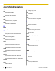
List of Abbreviations List of Abbreviations A CPC Calling Party Control AA Automated Attendant ACD Automatic Call Distribution ANI Automatic Number Identification CS Cell Station CT Call Transfer—QSIG CTI Computer Telephony Integration APT Analog Proprietary Telephone ARS Automatic Route Selection B D DID Direct Inward Dialing DIL Direct In Line BGM Background Music C DISA Direct Inward System Access DND CCBS Do Not Disturb Completion of Calls to Busy Subscriber DPT Call Forwarding—QSI
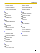
List of Abbreviations IP-PT SLT IP Proprietary Telephone IRNA Single Line Telephone SMDR Intercept Routing—No Answer ISDN Station Message Detail Recording SVM Integrated Services Digital Network L Simplified Voice Message T L-CO TAFAS Loop-CO LCS Trunk Answer from Any Station TEI Live Call Screening LED Terminal Endpoint Identifier TRG Light Emitting Diode Trunk Group TRS N Toll Restriction NDSS Network Direct Station Selection U UCD O Uniform Call Distribution OGM Outgoing
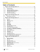
Table of Contents Table of Contents 1 Features and Configurations—A ..........................................................13 1.1 1.1.1 1.1.2 1.1.3 1.1.4 1.1.5 1.1.6 1.1.7 A ........................................................................................................................................14 Absent Message .............................................................................................................14 Account Code Entry ................................................
Table of Contents 5 Features and Configurations—E ..........................................................91 5.1 5.1.1 5.1.2 5.1.3 5.1.4 5.1.5 5.1.6 5.1.7 5.1.8 5.1.9 E ........................................................................................................................................92 EFA (External Feature Access) ......................................................................................92 Emergency Call ..................................................................
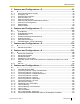
Table of Contents 10 Features and Configurations—L ........................................................175 10.1 10.1.1 10.1.2 10.1.3 10.1.4 L ......................................................................................................................................176 LED Indication ..............................................................................................................176 Line Preference—Incoming ........................................................................
Table of Contents 13.1.26 13.1.27 13.1.28 PS Feature Buttons ......................................................................................................266 PS Ring Group .............................................................................................................266 PT Programming ..........................................................................................................270 14 Features and Configurations—Q ........................................................
Table of Contents 21.4 Revision History ............................................................................................................363 21.4.1 KX-TDA600 PLMPR Software File Version 5.0xxx ......................................................363 21.4.2 KX-TDA100/KX-TDA200 PMPR Software File Version 1.1xxx ....................................363 21.4.3 KX-TDA100/KX-TDA200 PMPR Software File Version 2.0xxx ....................................364 21.4.
Section 1 Features and Configurations—A Document Version 2008-11 Feature Manual 13
1.1.1 Absent Message 1.1 A 1.1.1 Absent Message Description Extension users can prepare a brief text message (Absent Message) that will be displayed to other extension users when they are called. These messages can explain the reason for their absence, and may be edited through system programming and personal programming. The following Absent Messages may be programmed: Type Message No.
1.1.2 Account Code Entry PT Programming Manual References [008] Absent Message Feature Manual References 21.1 Capacity of System Resources Operating Manual References 1.3.1 Absent Message 3.1.2 Personal Programming 1.1.2 Account Code Entry Description An account code is used to identify outgoing CO line calls for accounting and billing purposes. The account code is appended to the Station Message Detail Recording (SMDR) call record.
1.1.3 ARS (Automatic Route Selection) PC Programming Manual References 4.8 [2-6-1] Numbering Plan—Main—Features— Account Code Entry 4.11 [2-7-1] Class of Service—COS Settings—CO & SMDR— Account Code Mode PT Programming Manual References [508] Account Code Mode Feature Manual References 3.1.19 COS (Class of Service) 6.1.3 Flexible Buttons 16.1.1 SMDR (Station Message Detail Recording) Operating Manual References 1.2.1 Making Calls 1.1.
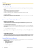
1.1.3 ARS (Automatic Route Selection) [Carrier Selection Procedure Flowchart] The numbers in parentheses indicate the corresponding items found under [Programming Procedures] on the following pages. An extension user accesses a CO line and dials a telephone number. Is the ARS mode (1) enabled? No (Normal CO Line Access) Sends the telephone number as dialed.
1.1.3 ARS (Automatic Route Selection) note that the CO Line Access number is always ignored by ARS and does not need to be programmed here. Calls that are exempt from ARS are connected to the user-selected line, via the default carrier for that line. [Programming Example: ARS Leading Number Exception Table] Leading No. Exception *1 Location No. 1 2 3 *1 555 556 567 ® 10.7 [8-6] Leading Number Exception ® [325] ARS Exception Number In this example: 555, 556, and 567 are local exchanges.
1.1.3 ARS (Automatic Route Selection) Since the preferred carrier may vary depending on the time of day, you can create an ARS-specific time table and break each day of the week into different time blocks. A different carrier can then be assigned to each time block. Routing Plan Time Table: For each Routing Plan, a different carrier can be assigned for each time of day and each day of the week. Each day can have up to four programmable time blocks.
1.1.
1.1.3 ARS (Automatic Route Selection) 10.8 [8-7] Authorization Code for TRG Itemized Billing Code An Itemized Billing Code can be assigned for each extension and for each verification code. If a call is not made from an extension, such as via Direct Inward System Access (DISA) or TIE line, and no verification code is used, the Itemized Billing Code assigned to location 1 in the Verification Code Table will be used. 6.1 [4-1-1] Wired Extension—Extension Settings—Option 1— ARS Itemized Code 6.
1.1.4 Automatic Callback Busy (Camp-on) Section 10 [8] ARS 13.
1.1.6 Automatic Fax Transfer 1.1.5 Automatic Extension Release Description After going off-hook, if an extension user fails to dial any digits within a preprogrammed time period, the user will hear a reorder tone. This operation applies to intercom calls only. This feature is also known as Automatic Station Release. Conditions • • A proprietary telephone (PT)/portable station (PS) user hears a reorder tone for a preprogrammed time period, and then the PT/PS returns to idle status automatically.
1.1.7 Automatic Time Adjustment Destination Availability DISA Analog/ISDN Remote Maintenance Idle Line Access no. + Phone no. Trunk Group Access no. + Trunk Group no. + Phone no. Extension of Another PBX (via TIE Line, Access with PBX Code) Extension of Another PBX (via TIE Line, Access without PBX Code) *1 A PS destination can be used to forward fax calls to a fax machine at another PBX connected by TIE line. A virtual PS can be specified as the destination of fax calls.
1.1.7 Automatic Time Adjustment – On the Daylight Saving Time end date, a reminder set for between 1:00 A.M. and 2:00 A.M. will ring twice. 2. Time Information from Telephone Company Time information can be received when – An incoming or outgoing call through an ISDN line is received/made. – An incoming call through an analog line with Caller ID which includes time information is received. The PBX clock will be adjusted everyday with the first call after 3:05 AM, if enabled through system programming.
1.1.
Section 2 Features and Configurations—B Document Version 2008-11 Feature Manual 27
2.1.1 BGM (Background Music) 2.1 B 2.1.1 BGM (Background Music) Description A proprietary telephone (PT) user can listen to background music (BGM) through the built-in speaker while on-hook and idle. BGM—External: BGM can also be broadcast in the office through external pagers (loudspeakers) and can be turned on and off by an extension assigned as a manager. Conditions [BGM] • Hardware requirement: A user-supplied external audio source, such as a CD player or radio.
2.1.1 BGM (Background Music) → MOH—MOH (Music On Hold) (KX-TDA50 only) 7.2 [5-2] External Pager Operating Manual References 1.3.5 BGM (Background Music) 2.1.
2.1.
Section 3 Features and Configurations—C Document Version 2008-11 Feature Manual 31
3.1.1 Caller ID 3.1 C 3.1.1 Caller ID Description The PBX can receive Caller ID information (a caller’s name and telephone number) from calls received on CO lines. This information can be shown on a proprietary telephone (PT) display when receiving a call and can be used to direct calls from specific callers to specific destinations automatically.
3.1.1 Caller ID Feature Description Details in Caller information is automatically recorded in the ® 3.1.3 Call Log, call log of the extension which received the call. This Incoming information can be used to view a record of incoming calls or make calls to any number in the call log. Incoming Call Log 3.
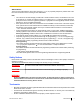
3.1.1 Caller ID A CO line call containing Caller ID information is received. Checks the Caller ID Modification Table assigned to the Trunk Group. Yes Is the caller's area code stored in the Caller ID Modification Table? No Modifies the number according to the method programmed in the corresponding "Local/International Call Data" field. Modifies the number according to the method programmed in the "Long Distance Code" field.
3.1.1 Caller ID [Programming Example: System Speed Dialing Table] *1 *2 *3 Location (System Speed Dialing No.) System Speed Dialing Name*1 Telephone No.*2 CLI Destination*3 000 ABC Company 912125551234 200 001 XYZ Company 913135551234 300 ® 8.1 [6-1] System Speed Dial— CO Line Access Number + Telephone Number ® [001] System Speed Dialing Number Name ® 8.1 [6-1] System Speed Dial— ® [002] System Speed Dialing Name CLI Destination ® 8.1 [6-1] System Speed Dial— 5.
3.1.2 Call Hold • • • • Even if the caller’s name is sent, the name may not be shown depending on the type of SLT. Incoming Call Log information is not shown on the SLT Caller ID shows whether the call is an intercom or CO line call by default. This setting can be disabled through system programming. A caller ID name received from the network via a PRI23 card will not be displayed on an SLT.
3.1.2 Call Hold Conditions • • • • • • • Call Hold Limitation A proprietary telephone (PT) user can hold one intercom call and/or multiple CO line calls at a time. A single line telephone (SLT) user can hold either one intercom call or one CO line call at a time. By using the Call Park feature, PT and SLT users can hold multiple CO line calls and intercom calls simultaneously. (® 3.1.5 Call Park) Music on Hold Music, if available, is sent to the held party. (® 11.1.
3.1.3 Call Log, Incoming Hold (to be Retrieved from Another Extension)*1 Hold Mode 4 *1 • Flashing the hookswitch + Hold Feature No. + Going on-hook Flashing the hookswitch + Hold Feature No. + Hold Feature No. + Going on-hook Transfer to CO Line Transfer to Extension Flashing the hookswitch + Hold Feature No. + CO Line Access No. Flashing the hookswitch + Hold Feature No. + Extension No.
3.1.3 Call Log, Incoming Each extension and incoming call distribution (ICD) group has its own Incoming Call Log. Call Log Button The Call Log button will alert an extension user to any missed (unanswered) calls. A flexible button can be customized as the Call Log button, and will indicate the status of the Incoming Call Log for the extension or corresponding ICD group, as shown below. Light pattern Status of the corresponding call log Red on There are call records in the log which have not been viewed.
3.1.3 Call Log, Incoming Conditions • The following information is logged.
3.1.4 Call Monitor • If the PBX is programmed to automatically modify incoming telephone numbers, the modified numbers will be logged in the Incoming Call Log. Incoming Call Log for Calls to an ICD Group If a call directed to an ICD group is not answered, the call is logged in the Incoming Call Log of the ICD group. If the call is answered, it is logged in the call log of the answering extension only.
3.1.4 Call Monitor Conditions • • • • Class of Service (COS) programming determines extension users who can use this feature. This feature is available only when the busy extension is in a conversation with another extension or outside party. This feature will not function when the busy extension: a. Has set Executive Busy Override Deny (® 5.1.3 Executive Busy Override) or Data Line Security (® 4.1.1 Data Line Security). b. Is receiving an Off-hook Call Announcement (OHCA) (® 12.1.
3.1.5 Call Park 3.1.5 Call Park Description An extension user can place a call into a common parking zone of the PBX. The Call Park feature can be used as a transferring feature; this releases the user from the parked call to perform other operations. A parked call can be retrieved by any extension user. Conditions • • • • • Automatic Call Park It is possible to select an idle parking zone automatically.
3.1.6 Call Pickup → Optional Parameter (or Ringing Tone Type Number) (for Call Park) 6.17 [4-3] DSS Console → Type → Parameter Selection (for Call Park) → Optional Parameter (Ringing Tone Type Number) (for Call Park) Feature Manual References 6.1.3 Flexible Buttons 21.1 Capacity of System Resources Operating Manual References 1.3.6 Call Hold 3.1.6 Call Pickup Description An extension user can answer a call ringing at any other extension.
3.1.7 Call Splitting [Group Call Pickup] • A specified number of call pickup groups can be created, each of which consists of extension user groups. One extension user group can belong to several call pickup groups. (® 7.1.1 GROUP FEATURES) [Example] Call Pickup Group 1 Call Pickup Group 2 Call Pickup Group 3 Extension User Group 1 Extension User Group 2 Extension User Group 3 Extension User Group 4 Extn. 100 Extn. 101 Extn. 102 Extn. 103 Extn. 104 Extn. 105 Extn. 106 Extn.
3.1.8 Call Transfer Conditions • When the extension user is having a conversation with one party, the other party is in consultation hold. (® 3.1.18 Consultation Hold) Operating Manual References 1.3.10 Call Splitting 3.1.8 Call Transfer Description An extension user can transfer a call to another extension or an outside party.
3.1.8 Call Transfer For the KX-TDA50/KX-TDA100/KX-TDA200, if the transfer destination has a destination set as Intercept Routing—No Answer, the call will be routed to that destination. A call is transferred without announcement.
3.1.8 Call Transfer Destination Availability Idle Line Access no. + Phone no. Trunk Group Access no. + Trunk Group no. + Phone no. Extension of Another PBX (via TIE Line, Access with PBX Code) Extension of Another PBX (via TIE Line, Access without PBX Code) *1 If the transfer destination does not answer, the call is sent to Voice Mail and a message can be recorded in the mailbox of the transfer destination. VM Group is only available as a destination for the KX-TDA50/KX-TDA100/KX-TDA200.
3.1.9 CALL WAITING FEATURES Feature Manual References 3.1.19 COS (Class of Service) Operating Manual References 1.3.11 Call Transfer 1.3.49 PDN (Primary Directory Number)/SDN (Secondary Directory Number) Extension (KX-TDA100/ KX-TDA200/KX-TDA600 only) 3.1.9 CALL WAITING FEATURES Description Used to inform a busy extension that another incoming call is waiting. The busy extension user can answer the second call by disconnecting the current call or placing it on hold.
3.1.9 CALL WAITING FEATURES • • answer the second call by disconnecting the current call or placing it on hold using EFA. For details, consult your telephone company. Call Waiting Caller ID (Visual Caller ID): When using the call waiting tone supplied by the telephone company over analog lines, the caller’s telephone number and name can be received. Either the name or the number will flash on the display for five seconds, followed by a 10-second pause, then flash again for five seconds.
3.1.10 Call Waiting Tone 3.1.10 12.1.3 16.1.1 20.1.3 Call Waiting Tone OHCA (Off-hook Call Announcement) SMDR (Station Message Detail Recording) Whisper OHCA Operating Manual References 1.3.12 CALL WAITING FEATURES 1.3.13 Call Waiting Tone 3.1.2 Personal Programming 3.1.10 Call Waiting Tone Description When an extension user attempts to call a busy extension (i.e.
3.1.12 CLI (Calling Line Identification) Distribution 3.1.11 CELLULAR PHONE FEATURES Description This PBX provides features to support the use of cellular phones and other outside destinations with the PBX. Calls can be forwarded from virtual PSs to outside destinations such as cellular phones, and then answered as if the user was at an extension within the PBX.
3.1.12 CLI (Calling Line Identification) Distribution CLI distribution works in conjunction with both Direct In Line (DIL) and Direct Inward Dialing (DID) distribution; it can be enabled or disabled for each CO line (for DIL) and for each DID number, for each time mode. When a call has Caller ID information and CLI distribution is enabled for the current time mode, CLI distribution will direct the call to its destination, ignoring preprogrammed DIL or DID destinations.
3.1.13 CLIP (Calling Line Identification Presentation) 16.1.4 Speed Dialing, System 3.1.13 CLIP (Calling Line Identification Presentation) Description Calling Line Identification Presentation (CLIP): The PBX can send a preprogrammed telephone number to the network when an extension user makes a call. The called party can see the number on his telephone display before answering the call.
3.1.13 CLIP (Calling Line Identification Presentation) Conditions • • • • • • • CLIP, COLP, CLIR, and COLR are only available for the KX-TDA100, KX-TDA200, and KX-TDA600. The availability of this feature is dependent on the contract with the telephone company. The CLIP/COLP number for the connected ISDN port can be used for the ISDN terminal devices which cannot be assigned their own CLIP/COLP number, such as a doorphone.
3.1.14 CO Line Access Feature Manual References 6.1.3 Flexible Buttons 21.2 Exclusive Features Table Operating Manual References 1.3.52 Private Network Features—CLIP (Calling Line Identification Presentation) 1.3.53 Private Network Features—CLIR (Calling Line Identification Restriction) 1.3.55 Private Network Features—COLR (Connected Line Identification Restriction) 3.1.14 CO Line Access Description There are three methods of accessing a CO line.
3.1.14 CO Line Access • • • • If an extension user is on-hook when pressing an idle CO button, the proprietary telephone (PT) automatically enables hands-free operation mode. The user can dial without lifting the handset or pressing the SP-PHONE button or MONITOR button. Group Hunting Order for Idle Line Access An idle CO line is selected from the trunk groups assigned for Idle Line Access.
3.1.15 CO Line Call Limitation Feature Manual References 3.1.19 COS (Class of Service) 6.1.3 Flexible Buttons Operating Manual References 1.2.1 Making Calls 3.1.15 CO Line Call Limitation Description CO line calls are limited by the following features: Feature Description Extension-to-CO Line Call Duration If a call between an extension user and an outside party is established, the call duration can be restricted by the system timer selected for each trunk group.
3.1.16 Conference → CO-CO Duration Time → Extension-CO Duration Time 9.5 [7-5] Miscellaneous— Dial Digits Limitation After Answering—Dial Digits PT Programming Manual References [472] Extension-to-CO Line Call Duration [473] CO-to-CO Line Call Duration [502] CO Line Call Duration Limitation Feature Manual References 3.1.19 COS (Class of Service) 3.1.16 Conference Description An extension user can establish a conference call by adding additional parties to an already existing two-party conversation.
3.1.17 Confirmation Tone Installation Manual References KX-TDA50 2.5.2 ECHO8 Card (KX-TDA5166) KX-TDA100/KX-TDA200 2.6.4 ECHO16 Card (KX-TDA0166) KX-TDA600 2.8.6 EECHO16 Card (KX-TDA6166) PC Programming Manual References 4.4 [2-3] Timers & Counters—Dial / IRNA / Recall / Tone → Unattended Conference—Recall Start Timer → Unattended Conference—Warning Tone Start Timer → Unattended Conference—Disconnect Timer 4.11 [2-7-1] Class of Service—COS Settings—TRS— Transfer to CO 4.
3.1.18 Consultation Hold Type Tone 3-1 Description a. Sent before a conversation is established using the Paging feature. b. Sent to the caller when a conversation is established with an extension in one of the following modes: • Hands-free Answerback mode • Voice-calling mode (Alternate Receiving—Ring/Voice) c. Sent when making a call to or from a doorphone.
3.1.19 COS (Class of Service) Feature Manual References 3.1.7 Call Splitting 3.1.8 Call Transfer 3.1.16 Conference 3.1.19 COS (Class of Service) Description Each extension must belong to a Class of Service (COS). By assigning certain extensions to a COS, it is possible to control the behavior and privileges of extension users (allowing or denying certain extensions access to various features, extensions, and CO lines) depending on the duties appointed to them.
3.1.21 CTI (Computer Telephony Integration) 6.1 [4-1-1] Wired Extension—Extension Settings—Main— 6.10 [4-2-1] Portable Station—Extension Settings—Main— COS COS PT Programming Manual References 2.1.8 COS Programming [602] Class of Service Feature Manual References 21.1 Capacity of System Resources 3.1.20 CPC (Calling Party Control) Signal Detection Description The Calling Party Control (CPC) signal is an on-hook indication (disconnect signal) sent from an analog CO line when the other party hangs up.
3.1.21 CTI (Computer Telephony Integration) by running customized Computer Telephony Integration (CTI) software, available from Panasonic (PC Console, PC Phone, etc.) as well as third-party software vendors. CTI can be achieved in two ways: 1. First Party Call Control 2. Third Party Call Control 1. First Party Call Control A PC is connected to a digital proprietary telephone (DPT) which supports an optional USB Module. Each PC acts independently; it is not necessarily connected to a server.
3.1.21 CTI (Computer Telephony Integration) • • • IP-PT CTI application software must be installed on the connected PC. In addition, some features may require a KX-TDA6920, KX-TDA0920, or KX-TDA5920 SD Memory Card for Software Upgrade to Enhanced Version. When using an IP-GW4 card, the firmware (not LPR software) of the card must be version 1.400 or later.
3.1.
Section 4 Features and Configurations—D Document Version 2008-11 Feature Manual 67
4.1.2 Dial Mode Selection 4.1 D 4.1.1 Data Line Security Description Once Data Line Security is set on an extension, communication between the extension and the other party is protected from signals such as Call Waiting, Hold Recall and Executive Busy Override. Extensions which have devices connected to them such as modems or fax machines may set this feature to maintain secure data transmission, by blocking tones or other interruptions during communication. PC Programming Manual References 4.
4.1.3 Dial Tone → Dialing Mode → DTMF Width → Pulse Speed 3.17 [1-1] Slot—Port Property - T1 Port (KX-TDA100/KX-TDA200/KX-TDA600 only) → CO Dial Mode → DTMF Width → CO Pulse Speed PT Programming Manual References [410] LCOT Dialing Mode [411] LCOT Pulse Rate [412] LCOT DTMF Minimum Duration 4.1.3 Dial Tone Description The following dial tones inform extension users about features activated on their extensions: Each dial tone type has two frequencies, such as dial tone 1A and dial tone 1B.
4.1.4 Dial Tone Transfer Type Description Tone 4A/4B *1 This tone is heard when new messages have been recorded for the extension. Active even when distinctive dial tones are disabled. Conditions • • • • Dial Tone Type A/B Through system programming, it is possible to select dial tone type A or B for dial tones 1 through 4. If "Type A" is selected, all dial tones 1 through 4 will become dial tone type A. The dial tone type for the ARS feature can be selected separately.
4.1.5 DID (Direct Inward Dialing) Conditions • • The modified TRS level only applies to the next one call placed at the user’s extension. Toll Restriction Button A manager extension must store the TRS level granted by the Dial Tone Transfer beforehand, when assigning a flexible button as the Toll Restriction button. PC Programming Manual References 6.5 [4-1-4] Wired Extension—Flexible Button → Type → Parameter Selection (for TRS Level Change) 6.
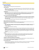
4.1.5 DID (Direct Inward Dialing) [Method Flowchart] A CO line call is received on a DID line. No Is the DID number found in the DID Table? Yes Does the call have Caller ID information and is CLI distribution enabled for the DID number in the current time mode? Does the DID number match an extension number? No No The call is routed to the extension. Yes Does the DID number match an extension number at another PBX or CO Line Access no.
4.1.6 DIL (Direct In Line) If the DID number is "123-4567": 1. The PBX looks for the DID number in the table and finds it in location 1. 2. The PBX checks the time mode. In day mode: Calling Line Identification (CLI) distribution is enabled. The call is routed to its CLI destination, if assigned. If not assigned, the call is routed to the DID destination, extension 105, and "Sales" is displayed. In lunch mode: CLI distribution is disabled.
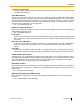
4.1.6 DIL (Direct In Line) [Method Flowchart] A CO line call is received. Does the call have Caller ID information and is CLI distribution enabled for the CO line in the current time mode? No Yes Has the caller been stored in the System Speed Dialing Table and has a CLI destination been assigned? Yes No No Is a DIL destination assigned for the current time mode? Yes The call is routed to its CLI destination. The call is routed to the DIL destination.
4.1.7 DISA (Direct Inward System Access) here is used to determine the Incoming Call Service and greeting message used by the Voice Processing System (VPS) during the current time mode. (19.1.4 Voice Mail DPT (Digital) Integration) Conditions • To use this feature, DIL must be assigned as the distribution method for the desired CO line port. PC Programming Manual References 12.2 [10-2] DIL Table & Port Settings—DIL → DIL Destination—Day, Lunch, Break, Night → Tenant Number → VM Trunk Group No.
4.1.7 DISA (Direct Inward System Access) [Flowchart] A DISA call from an outside party is received. No Is there a port available? Yes The call is routed to an operator, etc. (DISA Intercept when All DISA Ports are busy) (DISA Delayed Answer time expires) The PBX answers the call. (DISA Mute & OGM Start Time after Answering expires) A The OGM plays and the PBX starts to receive the DTMF signaling.
4.1.7 DISA (Direct Inward System Access) Continued from previous page No Security None CO Line Security B All Security Is the dialed number an extension number or floating extension number? No Yes Is the Walking COS/Verification Code Entry feature number dialed? C What is the dialed number? Yes No Yes Is the correct PIN entered? Extension No./ Floating Extension No. Feature No.* (Absent Message, FWD, etc.) CO Line Access No. + Telephone No. The feature is set.
4.1.7 DISA (Direct Inward System Access) Continued from previous page Continued from previous page What method is assigned for DISA Intercept Routing DND? Intercept Routing No Is an Intercept Routing Busy destination assigned? Busy tone press (Busy Tone / DND Tone Continuation time expires) OGM Does the caller while hearing a busy tone (Call Retry)? Yes The call is routed to the intercept destination.
4.1.7 DISA (Direct Inward System Access) *1 *2 *3 Outgoing Message (OGM) No. Floating Extn. No.*1 01 501 02 502 : : Automated Attendant No.*2 0 1 2 3 4 5 6 7 8 9 Busy/DND Message No.*3 100 301 200 103 202 101 102 400 104 205 04 05 : : : : : : : : : : : Floating Extension Number ® 7.4 [5-3-2] Voice Message—DISA Message— ® [730] Outgoing Message (OGM) Floating Extension Number ® 7.
4.1.7 DISA (Direct Inward System Access) DISA Intercept Routing—DND If the destination called by the outside party is in DND mode and Idle Extension Hunting is not available, one of the following can be selected through system programming: a. Busy Tone: The caller will hear a busy tone. b. Enable: DND will redirect the call to the preprogrammed destination on an extension basis. c. OGM: An outgoing message (OGM) will be sent to the caller.
4.1.7 DISA (Direct Inward System Access) CLI CO Line No. : DIL Destination Day Lunch ... Day Lunch ... : : : : : : "CLI" must be set to Disable, to allow incoming calls to be received by DISA. 12.2 [10-2] DIL Table & Port Settings → DIL— DIL Destination—Day, Lunch, Break, Night → CLI for DIL— CLI Ring for DIL—Day, Lunch, Break, Night [Programming Example of System Speed Dialing Table] Location Name CO Line Access + Telephone Number CLI Destination 000 J.
4.1.7 DISA (Direct Inward System Access) • • • • • 82 While hearing a ringback, reorder, or busy tone, retrying the call is possible by pressing " ". System programming selects whether pressing " " during a CO-to-CO line conversation returns to the DISA top menu or sends a DTMF tone. DISA Mute Time It is possible to set the Mute time until the outgoing message (OGM) plays and the PBX starts to receive the DTMF signaling after the caller reaches the DISA line. 4.
4.1.7 DISA (Direct Inward System Access) • • • • • An outside party such as a cellular phone can transfer a CO line call to an extension at the PBX by pressing "#" + extension number, if DISA is connected by the Automatic DISA Activation feature. This feature can be enabled or disabled through system programming. 7.
4.1.7 DISA (Direct Inward System Access) PC Programming Manual References 4.4 [2-3] Timers & Counters—DISA / Door / Reminder / U.
4.1.8 Display Information Operating Manual References 1.3.18 DISA (Direct Inward System Access) 1.3.72 Walking COS 4.1.
4.1.9 DND (Do Not Disturb) →Option 5— Automatic LCD Switch when Start Talking 6.10 [4-2-1] Portable Station—Extension Settings →Option 4— Display Language →Option 5— Incoming Call Display →Option 5— Automatic LCD Switch when Start Talking 12.1 [10-1] CO Line Settings— CO Name Operating Manual References 3.1.2 Personal Programming 4.1.9 DND (Do Not Disturb) Description An extension user can make use of the DND feature.
4.1.10 Door Open 6.3 [4-1-2] Wired Extension—FWD/DND → Call from CO—DND Status Availability → Call from Extension—DND Status Availability PT Programming Manual References [507] DND Override Feature Manual References 3.1.19 COS (Class of Service) Operating Manual References 1.3.19 DND (Do Not Disturb) 4.1.10 Door Open Description Using an extension telephone, an extension user can unlock a door for a visitor.
4.1.11 Doorphone Call 4.11 [2-7-1] Class of Service—COS Settings—CO & SMDR— Door Unlock PT Programming Manual References [207] Door Unlock Time [512] Permission for Door Open Access Feature Manual References 3.1.19 COS (Class of Service) Operating Manual References 1.3.20 Door Open 4.1.11 Doorphone Call Description A visitor can use a doorphone to call its preprogrammed destination. Extension users can call a doorphone.
4.1.11 Doorphone Call Installation Manual References KX-TDA50 2.5.1 DPH4 Card (KX-TDA5161) 2.9.1 Connection of Doorphones, Door Openers, External Sensors, and External Relays KX-TDA100/KX-TDA200 2.6.1 OPB3 Card (KX-TDA0190) 2.6.2 DPH4 Card (KX-TDA0161) 2.9.1 Connection of Doorphones, Door Openers, External Sensors, and External Relays KX-TDA600 2.8.1 OPB3 Card (KX-TDA0190) 2.8.2 DPH4 Card (KX-TDA0161) 2.12.
4.1.
Section 5 Features and Configurations—E Document Version 2008-11 Feature Manual 91
5.1.1 EFA (External Feature Access) 5.1 E 5.1.1 EFA (External Feature Access) Description Normally, an extension user can only access features within the PBX. However, when performing External Feature Access (EFA) the extension user performs features outside of the PBX, such as using the transfer services of the telephone company or host PBX. When EFA is performed, the PBX sends a flash/recall signal to the telephone company or the host PBX (® 8.1.
5.1.3 Executive Busy Override 5.1.2 Emergency Call Description An extension user can dial preprogrammed emergency numbers after seizing a CO line regardless of the restrictions imposed on the extension. Conditions • • • A specified number of emergency numbers can be stored. Emergency numbers may be called, regardless of Toll Restriction (TRS) level (® 17.1.6 TRS (Toll Restriction)), even when: – in Account Code—Forced mode (® 1.1.2 Account Code Entry) – in Extension Dial Lock (® 5.1.
5.1.4 Extension Dial Lock d. Is on a conference call (® 3.1.16 Conference, ® 13.1.12 Privacy Release). e. Is on a doorphone call (® 4.1.11 Doorphone Call). f. Is using Live Call Screening (LCS) or Two-way Record (® 19.1.4 Voice Mail DPT (Digital) Integration). g. Has a call on consultation hold (® 4.1.7 DISA (Direct Inward System Access)). • This feature is not available for a CO-to-CO line call via Direct Inward System Access (DISA). PC Programming Manual References 4.
5.1.5 Extension Feature Clear • Other features can also temporarily change an extension’s TRS level, similar to Extension Dial Lock. If an extension is locked, the TRS level determined by the following features takes priority. The numbers below (1 through 3) indicate the priority of each feature, with 1 having the highest priority, and 3 having the lowest. 1. Dial Tone Transfer (® 4.1.4 Dial Tone Transfer) 2. TRS Override by System Speed Dialing (® 17.1.6 TRS (Toll Restriction)) 3.
5.1.6 Extension PIN (Personal Identification Number) Features After Setting Paralleled Telephone Paired SLT will ring. Hot Line*1 Off Timed Reminder Cleared *1 These features can be programmed to not be canceled by Extension Feature Clear. This feature is also known as Station Program Clear. Conditions • • Extension Dial Lock (® 5.1.4 Extension Dial Lock) and the extension personal identification number (PIN) (® 5.1.
5.1.7 Extension Port Configuration Conditions CAUTION There is a risk that fraudulent telephone calls will be made if a third party discovers a personal identification number (PIN) (verification code PIN or extension PIN) of the PBX. The cost of such calls will be billed to the owner/renter of the PBX. To protect the PBX from this kind of fraudulent use, we strongly recommend: a. Keeping PINs secret. b. Selecting complex, random PINs that cannot be easily guessed. c. Changing PINs regularly.
5.1.7 Extension Port Configuration d. Super Hybrid Port: DPT, APT, SLT, DSS Console, Panasonic VPS, and PT-interface CS e. Hybrid Port (For KX-TDA50 only): APT, SLT, DSS Console, Panasonic VPS, and PT-interface CS EXtra Device Port (XDP): A Super Hybrid port can be used as an XDP port, allowing two telephones (a DPT and an SLT) to be connected to the same port of the PBX.
5.1.8 External Relay 5.1.8 External Relay Description By turning external device relays on and off, the PBX can control external devices such as alarms. When an extension user enters the External Relay Control feature number, the specified relay turns on for a preprogrammed length of time. When this timer expires, the relay turns off automatically. This gives the PBX simple control over other equipment, allowing an extension user to, for example, activate an alarm from his extension.
5.1.9 External Sensor Feature Manual References 3.1.19 COS (Class of Service) Operating Manual References 1.3.27 External Relay 5.1.9 External Sensor Description External sensing devices, such as security alarms or smoke detectors, can be connected to the PBX. When the PBX receives input from a sensor, a call is made to the preset destination, alerting the extension user.
5.1.9 External Sensor • • • • • • After a sensor has been activated, the PBX will ignore any further alerts from the same sensor for the duration specified by a timer. This timer can be set separately for each sensor. As long as the previous sensor call is still being performed, any further alerts from the same sensor are ignored. The assigned sensor name and/or number are shown on the display of PTs and PSs when a sensor call is received.
5.1.
Section 6 Features and Configurations—F Document Version 2008-11 Feature Manual 103
6.1.1 Fixed Buttons 6.1 F 6.1.1 Fixed Buttons Description Proprietary telephones (PTs), DSS Consoles, and Add-on Key Modules feature a wide variety of feature buttons and Line Access buttons, explained below. Note that certain models do not feature certain buttons. For a description of the buttons found on portable stations (PSs), please refer to the Operating Instructions for each PS.
6.1.1 Fixed Buttons Button Usage Flexible CO Used to access a CO line or trunk group when making or receiving a call according to the button’s preprogrammed CO Line Access method (Default: S-CO). Can also be customized as a different feature button. INTERCOM Used to make or receive intercom calls. AUTO ANS (Auto Answer)/ MUTE Used to receive an incoming call in hands-free mode, or used to mute the built-in microphone or handset during a conversation.
6.1.2 Flash/Recall/Terminate 6.1.2 Flash/Recall/Terminate Description A proprietary telephone (PT) user can use the FLASH/RECALL button (Flash/Recall mode or Terminate mode) or Terminate button (Terminate mode) to disconnect the current call and originate another call without hanging up. Flash/Recall Mode: Disconnects the line and the extension user hears the dial tone from the line used last.
6.1.3 Flexible Buttons 6.1.3 Flexible Buttons Description You can customize the flexible buttons and/or programmable feature (PF) buttons on PTs, Add-on Key Modules, and PSs through either system or personal programming. They can then be used to make or receive intercom or CO line calls or be used as feature buttons, as follows: [Button Usage] Button Usage Single-CO (S-CO) Used to access a specified CO line for making or receiving calls. (® 3.1.
6.1.3 Flexible Buttons Button 108 Usage Call Log Used to show a log of received calls. (® 3.1.3 Call Log, Incoming) Log-in/Log-out*1 Used to switch between Log-in and Log-out status. (® 9.1.3 ICD Group Features—Log-in/Log-out) Hurry-up Used to redirect the longest waiting call in the queue of an ICD group to the overflow destination. (® 9.1.6 ICD Group Features— Queuing) Wrap-up*1 Used to switch between Wrap-up/Not Ready and Ready modes. (® 9.1.
6.1.4 Flexible Numbering/Fixed Numbering Button Usage Voice Mail (VM) Transfer Used to transfer a call to the mailbox of a specified extension. (® 19.1.4 Voice Mail DPT (Digital) Integration, ® 19.1.5 Voice Mail DTMF Integration) Check-in Used to switch the status of extensions from Check-out to Check-in. (® 15.1.3 Room Status Control) Check-out Used to switch the status of extensions from Check-in to Check-out. (® 15.1.
6.1.4 Flexible Numbering/Fixed Numbering 1. Flexible Numbering (available while a dial tone is heard) 2. Flexible Numbering (available while busy, DND, or ringback tone is heard) 3. Fixed Numbering (available while dialing or talking) 1. Flexible Numbering (available while a dial tone is heard) Extension numbers and feature numbers which are available while a dial tone is heard can be customized for easy use. The numbers must not conflict.
6.1.
6.1.
6.1.
6.1.
6.1.4 Flexible Numbering/Fixed Numbering Feature Fixed Numbering Conference 3 Door Open 5 Conditions • • • • • The following are examples of feature number conflicts: 1 and 11, 0 and 00, 2 and 21, 10 and 101, 32 and 321, etc. Feature number + Additional number (Parameter) Certain flexible feature numbers require additional digits to make the feature active.
6.1.5 Floating Extension 6.1.5 Floating Extension Description Virtual extension numbers can be assigned to resources to make them as easily accessible as extensions. These numbers are referred to as "floating extension numbers" and can be assigned as a destination of incoming calls, intercepted calls, etc. This feature is also known as Floating Station. Resource Device Group Description Default External Pager Used as the destination for the Trunk Answer From Any Station (TAFAS) feature. (® 17.1.
6.1.6 FWD (Call Forwarding) PT Programming Manual References [623] Incoming Call Distribution Group Name [660] VM Group Floating Extension Number [700] External Pager Floating Extension Number [730] Outgoing Message (OGM) Floating Extension Number [731] Outgoing Message (OGM) Name [811] Modem Floating Extension Number [812] ISDN Remote Floating Extension Number (KX-TDA100/KX-TDA200/KX-TDA600 only) Feature Manual References 13.1.6 PC Programming 19.1.3 Voice Mail (VM) Group 6.1.
6.1.6 FWD (Call Forwarding) Depending on the type of incoming intercom or CO line calls, it is possible to set a different destination for each.
6.1.6 FWD (Call Forwarding) Condition for Original Extension/ Incoming Call Distribution Group Destination Availability Extension of Another PBX (via TIE Line, Access with PBX Code) ü Only available when FWD to CO line is allowed through COS programming. Extension of Another PBX (via TIE Line, Access without PBX Code) ü – *1 If an extension user is not permitted by COS to call a certain extension (® 9.1.
6.1.6 FWD (Call Forwarding) In the above cases, the forwarding counter resets to zero, and the call can be forwarded up to four times again from the destination extension described above. Incoming call 1 A 2 B 3 C Original destination • 1 D 2 E F FWD—No Answer Boss & Secretary feature It is possible to call the original extension from the destination extension regardless of the forward setting.
6.1.7 FWD/DND Button, Group FWD Button 6.12 [4-2-2] Portable Station—FWD/DND PT Programming Manual References [472] Extension-to-CO Line Call Duration [473] CO-to-CO Line Call Duration [504] Call Forwarding to CO Line [605] Call Forwarding—No Answer Time Feature Manual References 3.1.19 COS (Class of Service) 9.1.5 ICD Group Features—Overflow 9.1.9 Idle Extension Hunting 9.1.11 Intercept Routing Operating Manual References 1.3.29 FWD (Call Forwarding) 6.1.
6.1.
6.1.7 FWD/DND Button, Group FWD Button • When both the FWD and DND features are assigned simultaneously, pressing the button changes the settings as follows: FWD • DND Off A FWD/DND button customized on a flexible button is always in FWD/DND Cycle Switch mode, and the mode cannot be changed. PC Programming Manual References 4.
6.1.
Section 7 Features and Configurations—G Document Version 2008-11 Feature Manual 125
7.1.1 GROUP FEATURES 7.1 G 7.1.1 GROUP FEATURES Description This PBX supports various types of groups. 1. Trunk Group CO lines can be grouped into trunk groups based on carrier, CO line type, etc. Several settings can be assigned on a trunk group basis. All CO lines belonging to a trunk group follow the programming for that trunk group. 5.1 [3-1-1] Trunk Group—TRG Settings [402] LCOT Trunk Group Number Each CO line can belong to only one trunk group.
7.1.1 GROUP FEATURES [Example] Call Pickup Group 1 Call Pickup Group 2 Call Pickup Group 3 Extension User Group 1 Extension User Group 2 Extension User Group 3 Extension User Group 4 Extn. 100 Extn. 101 Extn. 102 Extn. 103 Extn. 104 Extn. 105 Extn. 106 Extn. 107 Paging Group Using the Paging feature, extensions can make a page to any paging group or answer a page to their own groups. One extension user group or external pager (loudspeaker) can belong to several paging groups. (® 13.1.
7.1.1 GROUP FEATURES [Example] ICD Group 1 (Floating Extn. No. 601, Name: Sales 1) ICD Group 2 (Floating Extn. No. 602, Name: Sales 2) Extn. 103 Extn. 104 Extn. 105 Extn. 106 Extn. 107 Extn. 100 Extn. 101 Extn. 102 5. VM Group There are two types of VM groups, explained below. Type Description VM (DPT) Group A group of DPT ports which use Voice Mail DPT (Digital) Integration features. One DPT port can belong to only one group.
7.1.1 GROUP FEATURES 5.25 [3-9] PS Ring Group—Member List PS Ring Group 1 Floating Extension No. 301 Name: Sales 1 PS 1 (Extn. 601) PS 2 (Extn. 602) PS Ring Group 2 Floating Extension No. 302 Name: Sales 2 PS 3 (Extn. 603) PS 4 (Extn. 701) PS 5 (Extn.
7.1.
Section 8 Features and Configurations—H Document Version 2008-11 Feature Manual 131
8.1.1 Hands-free Answerback 8.1 H 8.1.1 Hands-free Answerback Description A proprietary telephone (PT) user with a speakerphone or optional headset can talk to a caller without lifting the handset. If the user receives a call in Hands-free Answerback mode, a hands-free conversation is established in the following method: Type Answering Method Intercom Call Established immediately after a beep tone at the called extension and the caller hears a confirmation tone.
8.1.3 Headset Operation Feature Manual References 9.1.13 Intercom Call Operating Manual References 1.3.30 Hands-free Answerback 8.1.2 Hands-free Operation Description A proprietary telephone (PT) user can talk to another party without lifting the handset. Pressing specific buttons, such as REDIAL, automatically activate hands-free mode. Conditions • PTs with the MONITOR Button PTs with the MONITOR button can dial in hands-free mode but cannot have hands-free conversations.
8.1.5 Host PBX Access Code (Access Code to the Telephone Company from a Host PBX) • Headset users cannot use the following features: – Automatic Redial (® 15.1.1 Redial, Last Number) – Receiving the Off-hook Call Announcement (OHCA) (® 12.1.3 OHCA (Off-hook Call Announcement)) – Receiving the Whisper OHCA (® 20.1.3 Whisper OHCA) PC Programming Manual References 3.5 [1-1] Slot—Port Property - Extension Port— Headset OFF/ON 3.
8.1.5 Host PBX Access Code (Access Code to the Telephone Company from a Host PBX) A preprogrammed Pause time will be automatically inserted between the user dialed Host PBX Access code and the subsequent digits (® 13.1.4 Pause Insertion). [Example] Telephone Company Host PBX Access Code: 0 Host PBX Outside Party (01-23-4567) Idle Line Access No.: 9 Extn. 101 Extn. 102 Dials "0-01-23-4567". TRG1 Host PBX Access Code PBX Telephone No. Dials "9-0-01-23-4567". Idle Line Access No. Telephone No.
8.1.6 Hot Line • A Host PBX Access Code can be used to record only long distance calls on SMDR when a CO line port is connected directly to the telephone company (not a host PBX). This is allowed when the long distance code (e.g., "0") is assigned as the Host PBX Access code. All local calls (e.g.
8.1.6 Hot Line PT Programming Manual References [204] Hot Line Waiting Time Feature Manual References 21.1 Capacity of System Resources Operating Manual References 1.3.
8.1.
Section 9 Features and Configurations—I Document Version 2008-11 Feature Manual 139
9.1.1 ICD GROUP FEATURES 9.1 I 9.1.1 ICD GROUP FEATURES Description An incoming call distribution group is a group of extensions programmed through system programming. 5.13 [3-5-1] Incoming Call Distribution Group—Group Settings—Member List [620] Incoming Call Distribution Group Member An incoming call distribution group receives calls directed to the group. Each incoming call distribution group has a floating extension number (default: 6 + two-digit group number).
9.1.1 ICD GROUP FEATURES Calls arrive at ICD group 1. 13 12 F Overflow Feature a) Sends a busy tone (Busy on Busy), or b) Redirects to the overflow destination. 11 10 9 D Queuing Feature 8 Five calls are waiting in the queue. (Calls 4 through 8) 7 6 Calls are distributed using the assigned method. Extn. 101 Extn. 100 Monitors or controls the status of the ICD group. *1 *2 *3 The longest waiting call in a queue can be redirected to the overflow destination by pressing the Hurry-up button.
9.1.1 ICD GROUP FEATURES A call is redirected to a preprogrammed destination when it cannot be answered or queued (Intercept Routing—Overflow in an Incoming Call Distribution Group). It is also possible to send a busy tone (Busy on Busy) or disconnect the line. 5. Incoming Call Distribution Group Controlling Feature Feature Log-in/Log-out Description & Reference Member extensions can join the group to handle calls (Log-in) or leave the group for a break (Log-out).
9.1.2 ICD Group Features—Group Call Distribution • The FWD feature can be assigned on an incoming call distribution group basis. COS for Incoming Call Distribution Groups Each incoming call distribution group is assigned a COS number. Group FWD to an outside party can be enabled or disabled for each COS.
9.1.2 ICD Group Features—Group Call Distribution One of the three distribution methods below can be assigned to each incoming call distribution group. Distribution Method Description Uniform Call Distribution (UCD) Calls are distributed evenly to a different extension each time a call is received. Extensions are hunted in a circular way in the preprogrammed order for the group, starting at the extension after the extension that received the last call. Received the last call. Extn. D Extn. C Extn.
9.1.2 ICD Group Features—Group Call Distribution [How the Group Call Waiting Feature Activates] Programming Conditions Result Group Call Group Call Waiting Mode Distribution Method Distribution UCD Priority Hunting Ring All UCD/Priority Hunting/ Ring Group Call Waiting Capable Distribution Method Telephone PT/PS with idle UCD ICD Group button Priority Hunting Any telephone Not available* Ring * Incoming calls enter the queue immediately. Member extensions do not receive the Call Waiting tone.
9.1.3 ICD Group Features—Log-in/Log-out Conditions • • • Automatic Call Distribution (ACD) – When a KX-TDA6920, KX-TDA0920 or KX-TDA5920 SD Memory Card for Software Upgrade to Enhanced Version is installed in the PBX, and the distribution type is set to Uniform Call Distribution, it is possible to select whether incoming calls are distributed to idle extensions evenly in order (UCD), or to the extension that has been idle the longest (ACD). – ACD does not work for PS Ring Groups.
9.1.3 ICD Group Features—Log-in/Log-out [Log-in/Log-out and Wrap-up Status Example] Incoming call Incoming call Incoming call Ready Call arrives Extn. 101 Extn. 102 Ready Extn. 103 Extn. 104 Extn. 105 Extn. 106 Waiting for call Wrap-up time expires Answering a call Wrap-up button pressed Not Ready Finishing paperwork/ temporary break Ready Not Ready Wrap-up Ready Wrap-up button pressed Call completed Logged-in Wrap-up Finishing paperwork Extn.
9.1.3 ICD Group Features—Log-in/Log-out A flexible button can be customized as the Wrap-up button. It shows the current status as follows: Light pattern • • • • Status Slow red flashing Wrap-up Red on Not Ready Off Ready (Wrap-up mode cancel) When a PS in Wireless XDP Parallel Mode completes a call, neither the PS nor its wired telephone can have Wrap-up time. (® 20.1.
9.1.4 ICD Group Features—Outside Destinations Feature Manual References 6.1.3 Flexible Buttons Operating Manual References 1.3.38 ICD Group Features—Log-in/Log-out 9.1.4 ICD Group Features—Outside Destinations Description Up to 4 outside parties or destinations at another PBX can be assigned as members of an Incoming Call Distribution (ICD) Group, using the following method: A virtual PS is registered as a member of the ICD Group.
9.1.4 ICD Group Features—Outside Destinations Conditions [General] • Hardware Requirement • • • • • • • • The KX-TDA6920, KX-TDA0920 or KX-TDA5920 SD Memory Card for Software Upgrade to Enhanced Version For this feature to be activated, the following conditions must be met: – A virtual PS is assigned as a member of the ICD Group. (® 19.1.2 Virtual PS) – The forwarding type of the virtual PS is set to All Calls. (® 6.1.
9.1.5 ICD Group Features—Overflow [621] Incoming Call Distribution Group Delayed Ringing [622] Incoming Call Distribution Group Floating Extension Number [624] Incoming Call Distribution Group Distribution Method [690] PS Registration Feature Manual References 13.1.16 Private Network Features—Network ICD Group 19.1.2 Virtual PS 9.1.
9.1.5 ICD Group Features—Overflow Destination Availability DISA ü Analog/ISDN Remote Maintenance ü Idle Line Access no. + Phone no. ü Trunk Group Access no. + Trunk Group no. + Phone no. ü Extension of Another PBX (via TIE Line, Access with PBX Code) ü Extension of Another PBX (via TIE Line, Access without PBX Code) ü 2.
9.1.6 ICD Group Features—Queuing [632] Maximum Number of Agents Feature Manual References 9.1.6 ICD Group Features—Queuing 9.1.6 ICD Group Features—Queuing Description When a preprogrammed number of extensions in an incoming call distribution group are busy, additional incoming calls can wait in a queue. The number of calls which can wait in the queue is programmable.
9.1.6 ICD Group Features—Queuing Sequence*1 Queuing TimeTable No. Sequence 01 Sequence 02 Sequence 03 Sequence 04 ... : : : : : : *1 *2 5.14 [3-5-2] Incoming Call Distribution Group—Queuing Time Table—Queuing Time Table— Queuing Sequence—Sequence 01–16 [631] Sequences in Queuing Time Table If a call has not reached a destination by the time the final sequence is completed, the call will be disconnected. Explanation for Queuing Time Table 01: Queuing Time Table 01 The call enters the queue.
9.1.7 ICD Group Features—Supervisory 5.12 [3-5-1] Incoming Call Distribution Group—Group Settings →Overflow Queuing Busy →Overflow No Answer →Queuing Time Table →Miscellaneous— Extension No Answer Redirection Time →Miscellaneous— Maximum No. of Busy Extension 5.14 [3-5-2] Incoming Call Distribution Group—Queuing Time Table 5.18 [3-7-1] VM(DPT) Group—System Settings— Call Waiting on VM Group 5.21 [3-8-1] VM(DTMF) Group—System Settings— Others—Call Waiting on VM Group 6.
9.1.7 ICD Group Features—Supervisory Feature Description Log-in/Log-out Monitor and Remote Control Monitor: The supervisor extension can monitor the log-in/log-out status of the incoming call distribution group members through the corresponding DSS button light. Remote Control: The supervisor extension can change the status of the members by pressing the corresponding DSS button. [Example] JAN.31 08:13AM FRI 601:Sales Section Waiting Calls Now :00006 Max.
9.1.8 ICD Group Features—VIP Call • • If a call to an incoming call distribution group is overflowed: If the display is in idle status, it will change to monitor mode for the corresponding incoming call distribution group automatically. If the display is monitoring another incoming call distribution group, it will not change. Other Features while in Monitor Mode The supervisor can use other features on the extension (making calls, pressing the MESSAGE button, etc.) even while in monitor mode.
9.1.9 Idle Extension Hunting [Example] In the call center, incoming call distribution groups 1 and 3 enable the VIP Call mode, while incoming call distribution groups 2 and 4 disable the VIP Call mode. Calls have been distributed by DIL/DID/CLI distribution. (The circled numbers indicate the arrival order of the calls. ICD Group 1 (for VIPs) ICD Group 2 (for general customers) 6 5 1 3 1st Priority Extn. 101 3rd Priority Extn. 102 Extn.
9.1.9 Idle Extension Hunting Type Description Circular Hunting An idle extension is searched for in the order specified in the idle extension hunting group in a circular way. Incoming call Busy Extn. Extn. Extn. Extn. Assignment order Terminated Hunting An idle extension is searched for in the order specified in the idle extension hunting group until reaching the last assigned extension. Incoming call Last Extn. Busy Extn. Extn. Extn.
9.1.10 INCOMING CALL FEATURES Destination Extension of Another PBX (via TIE Line, Access without PBX Code) • Availability ü FWD/DND Mode While searching for an idle extension within an idle extension hunting group, any extension that has set FWD—All Calls or DND feature will be skipped, and the call will go to the next extension in the group. PC Programming Manual References 5.16 [3-6] Extension Hunting Group 5.
9.1.10 INCOMING CALL FEATURES CO Line Card Port (Channel) Type Networking Type Public Private LCOT T1 PRI ELCOT / LCOT GCOT DID TIE (E&M) OPX (EXTN.) CO Extension QSIG-Master QSIG-Slave IP-GW Default Available 2. Distribution Method Each public CO line port (channel) can use a different method of directing calls to their destinations as they are received. Distribution Method Description Details in Direct In Line (DIL) Directs a call to a preprogrammed destination, ® 4.1.
9.1.10 INCOMING CALL FEATURES 3. Available Distribution Method for Public CO Lines CO Line Card Port (Channel) Type Distribution Method DIL DID LCOT T1 PRI ELCOT / LCOT GCOT DID TIE (E&M) CO Default Available 4. Available Destination The following destination types can be programmed as DIL, DID, or CLI destinations. Destination Type Availability Wired Extension (PT/SLT/T1-OPX) ü PS ü ICD Group ü PS Ring Group ü Floating Extension no.
9.1.11 Intercept Routing Type Description Details in No Answer (IRNA) If a called party does not answer a call within a ® 9.1.11 Intercept preprogrammed time period (Intercept time), the Routing call is redirected to a preprogrammed destination. Busy If a called party is already handling another call, the new call is redirected to a preprogrammed destination. DND If a called party is in Do Not Disturb (DND) mode, the call is redirected to a preprogrammed destination.
9.1.11 Intercept Routing Type No Destination Description If a call has no destination (i.e., if a destination is not assigned), the call is redirected to an operator. (® 9.1.12 Intercept Routing—No Destination) Intercept Routing redirects calls to destinations based on the original destination of the call, as shown in the table below. Different intercept destinations can be programmed for each time mode.
9.1.11 Intercept Routing When the original destination is: • • • • The Available Intercept Destination is: Not assignable (Intercept Routing is not available.) PS Ring Group*2 *2 External Pager (TAFAS) Analog/ISDN Remote Maintenance Other PBX Extension (TIE with no PBX Code) Intercept Routing for DISA will redirect a call only if all of the Direct Inward System Access (DISA) ports are busy.
9.1.11 Intercept Routing Intercept Destination Availability Trunk Group Access no. + Trunk Group no. + Phone no. ü Extension of Another PBX (via TIE Line, Access with PBX Code) ü Extension of Another PBX (via TIE Line, Access without PBX Code) ü Conditions • • • • • • • • • 166 If the intercept destination is busy or in DND mode and therefore cannot receive the call: a.
9.1.12 Intercept Routing—No Destination PC Programming Manual References 4.4 [2-3] Timers & Counters →Dial / IRNA / Recall / Tone— Intercept Routing No Answer (IRNA)—Day, Lunch, Break, Night →DISA / Door / Reminder / U. Conf— DISA—Intercept Timer—Day, Lunch, Break, Night 5.12 [3-5-1] Incoming Call Distribution Group—Group Settings →Overflow No Answer— Time out & Manual Queue Redirection—Destination-Day, Lunch, Break, Night 6.
9.1.13 Intercom Call PC Programming Manual References 4.3 [2-2] Operator & BGM— 12.6 [10-4] Miscellaneous— programmed.) PBX Operator—Day, Lunch, Break, Night Intercept—Routing to Operator - No Destination (Destination is not PT Programming Manual References [006] Operator Assignment Feature Manual References 12.1.5 Operator Features 9.1.13 Intercom Call Description An extension user can call another extension user.
9.1.14 Internal Call Block Type Description DND Tone Indicates the called party has set DND. PC Programming Manual References 4.10 [2-6-3] Numbering Plan—B/NA DND Call Feature— 6.1 [4-1-1] Wired Extension—Extension Settings →Main— Extension Number →Main— Extension Name →Option 4— Intercom Call by Voice 6.
9.1.14 Internal Call Block In this example: a. COS 1 can make calls to all extensions. b. COS 2 can make calls to COS 1 only. (COS 2 cannot make calls to COS 2.) c. COS 3 can make calls to COS 3 only. COS 1 Extn. 100 Extn. 101 COS 2 Extn. 102 COS 3 Extn. 103 Extn. 104 Extn. 105 Extn. 106 Conditions • • • Internal Call Block also prohibits certain features, such as Walking Extension and Walking COS, from being performed between certain extensions.
9.1.15 IP-PT (IP Proprietary Telephone) 9.1.15 IP-PT (IP Proprietary Telephone) Description This PBX supports the connection of IP proprietary telephones (IP-PTs), which function almost identically to normal PTs. However, they connect to the PBX over a Local Area Network (LAN), and send and receive calls using Internet Protocol (IP). IP-PTs have two Ethernet ports for connection, primary and secondary.
9.1.16 ISDN (INTEGRATED SERVICES DIGITAL NETWORK) FEATURES A KX-NT300 series IP-PT can automatically connect to a secondary PBX, when the primary PBX becomes disconnected. Installation Manual References KX-TDA50 2.4.8 IP-EXT4 Card (KX-TDA5470) KX-TDA100/KX-TDA200 2.5.8 IP-EXT16 Card (KX-TDA0470) KX-TDA600 2.7.8 IP-EXT16 Card (KX-TDA0470) PC Programming Manual References 3.22 [1-1] Slot—Card Property - IP Extension 3.24 [1-1] Slot—Port Property - IP-Extension Port 9.1.
9.1.16 ISDN (INTEGRATED SERVICES DIGITAL NETWORK) FEATURES Service Description Calling Line Identification Sends the caller’s telephone number to the Presentation (CLIP) network when making a call. The called party can see the number on his or her telephone display before answering the call. Connected Line Identification Presentation (COLP) Details in ® 3.1.13 CLIP (Calling Line Identification Presentation) Sends the telephone number of the answered party to the network when answering a call.
9.1.16 ISDN (INTEGRATED SERVICES DIGITAL NETWORK) FEATURES 6.10 [4-2-1] Portable Station—Extension Settings—Option 6— ISDN Bearer PC Programming Manual References 3.13 [1-1] Slot—Card Property - PRI type (KX-TDA100/KX-TDA200/KX-TDA600 only) 3.14 [1-1] Slot—Port Property - PRI Port (KX-TDA100/KX-TDA200/KX-TDA600 only) 3.15 [1-1] Slot—Port Property - PRI Port—Connection Command (KX-TDA100/KX-TDA200/KX-TDA600 only) 4.4 [2-3] Timers & Counters—Dial / IRNA / Recall / Tone— Dial—Extension Inter-digit 4.
Section 10 Features and Configurations—L Document Version 2008-11 Feature Manual 175
10.1.1 LED Indication 10.1 L 10.1.1 LED Indication Description The LED of the Message/Ringer Lamp and the following buttons (Line Status Buttons and Corresponding Extension Status Button) can indicate line status with a variety of light patterns. Line Status Buttons: S-CO, G-CO, L-CO, INTERCOM, ICD Group, PDN Corresponding Extension Status Button: DSS, SDN 1.
10.1.1 LED Indication 2. Light Pattern of the Line Status Buttons Line Status Button: CO Line Status Light Pattern S-CO G-CO Off Green on L-CO Idle Intercom Line Status Incoming Call Distribution (ICD) Group Line Status INTERCOM ICD Group This extension is using the line. Slow green flashing This extension is holding the line. Moderate green flashing This extension is holding the line using Exclusive Hold or using the line for an Unattended Conference.
10.1.2 Line Preference—Incoming 4. Flashing Light Patterns 1s Slow Flashing Moderate Flashing Rapid Flashing Conditions • • The incoming CO line call shows on the buttons in the following priority: ICD Group®S-CO®G-CO®L-CO®PDN®INTERCOM The light pattern of a DSS button for incoming calls can be set to "Off" through system programming. In this case, the DSS button light will not indicate the status of the corresponding extension. PC Programming Manual References 4.
10.1.3 Line Preference—Outgoing Type Description PDN (KX-TDA100/KX-TDA200/ KX-TDA600 only) Answers a call arriving at a Primary Directory Number (PDN) button simply by going off-hook. This works even when multiple calls are received simultaneously. (® 13.1.7 PDN (Primary Directory Number)/SDN (Secondary Directory Number) Extension) Prime Line Answers a call arriving at a CO button (on which the "Prime Line" is assigned) simply by going off-hook.
10.1.4 Local Alarm Information Method Prime Line Description When an extension user goes off-hook, the preset line is selected automatically. A prime line can be selected from the Line Access buttons: S-CO, G-CO, L-CO, ICD Group. Conditions • • Line Preference Override A user can override the preset Line Preference temporarily by pressing the desired Line Access button or a Memory Dialing button, such as One-touch Dialing, before going off-hook.
10.1.4 Local Alarm Information [Error Example] ERR #100 (10000) (1) (2) [Explanation] Number in the Example Item Description (1) Error Code Shows three-digit error code. (2) Sub Code Shows five-digit sub code (XYYZZ). X: Shelf number (1–4) YY: Slot number (00–11) ZZ: Physical port number (01–16) Conditions • • • • System Alarm Button Any flexible button can be customized as the System Alarm button.
10.1.4 Local Alarm Information →SMDR— Print Information—Error Log →Maintenance— Local Alarm Display—Extension 1, Extension 2 →Maintenance— Daily Test Start Time—Set →Maintenance— Daily Test Start Time—Hour →Maintenance— Daily Test Start Time—Minute Feature Manual References 6.1.3 Flexible Buttons 16.1.
Section 11 Features and Configurations—M Document Version 2008-11 Feature Manual 183
11.1.1 Manager Features 11.1 M 11.1.1 Manager Features Description An extension assigned as a manager (manager extension) is allowed to use certain features which most extensions cannot. Class of Service (COS) programming determines which extensions are manager extensions and can therefore use the following features: Feature Manager Programming 184 Manager Password Change Description & Reference Changes the manager password.
11.1.2 MEMORY DIALING FEATURES Conditions CAUTION There is a risk that fraudulent telephone calls will be made if a third party discovers a personal identification number (PIN) (verification code PIN or extension PIN) of the PBX. The cost of such calls will be billed to the owner/renter of the PBX. To protect the PBX from this kind of fraudulent use, we strongly recommend: a. Keeping PINs secret. b. Selecting complex, random PINs that cannot be easily guessed. c. Changing PINs regularly.
11.1.2 MEMORY DIALING FEATURES Feature Storing Method Details in ® 16.1.3 Speed Dialing, Personal Personal • • • System System Programming ® 16.1.4 Speed Dialing, System Quick Dialing System Programming (PC Programming only) ® 14.1.1 Quick Dialing Hot Line • • • Personal Programming Personal Operation with the Feature Number System Programming (PC Programming only) ® 8.1.6 Hot Line Incoming Call Log Incoming call information is automatically stored. ® 3.1.
11.1.3 Message Waiting [Secret Dialing Example] When storing the number "9-123-456-7890", to conceal the telephone number "123-456-7890", Enter 9 INTERCOM 1 2 3 4 5 6 7 8 9 0 INTERCOM . Note • • It is possible to store a Memory Dialing feature number at the beginning of Memory Dialing numbers. It is possible to store several feature numbers in one Memory Dialing location.
11.1.3 Message Waiting • 188 If Distinctive Dial mode is enabled, dial tone 4 will be sent to an extension when a message has been left on the extension. (® 4.1.3 Dial Tone) SLT with a Message Waiting Lamp (KX-TDA100/KX-TDA200/KX-TDA600 only) The lamp activates in the same way as the MESSAGE button on a PT provided an EMSLC or MSLC card is connected to the PBX. The preferred Message Waiting Lamp light pattern can be selected from the twelve patterns shown below.
11.1.3 Message Waiting [SLT Message Waiting Lamp Light Patterns] 5.12 s 1.28 s Pattern 1 ON OFF 5.12 s 1.28 s Pattern 2 ON OFF 512 ms 5.12 s 1.28 s ON Pattern 3 Pattern 4 OFF 256 ms 2.56 s 768 ms ON OFF 256 ms 5.12 s 768 ms Pattern 5 ON OFF 256 ms 2.56 s 512 ms Pattern 6 ON OFF 10.24 s 1.28 s Pattern 7 ON OFF 256 ms 20.48 s 1.28 s Pattern 8 ON OFF 256 ms 10.24 s 1.28 s Pattern 9 ON OFF 20.48 s Pattern 10 ON 1.
11.1.3 Message Waiting 10.24 s 10.24 s 20.48 s 10.24 s 20.48 s t t=1.28 s Pattern 11 ON OFF 10.24 s t t=1.28 s Pattern 12 ON OFF • • • • It is possible to leave a Message Waiting notification while hearing a ringback tone, busy tone, or DND tone. Messages are always left on the original destination extension, regardless of that extension’s FWD settings. (® 6.1.6 FWD (Call Forwarding)) Both the calling extension and the called extension can cancel a notification after it has been left.
11.1.4 Music on Hold 11.1.4 Music on Hold Description Music can be played to any party on hold. The following audio sources are available: a. Internal music source b. External music source c. Tone Music Source Assignment [KX-TDA100/KX-TDA200/KX-TDA600] BGM1, BGM2, and tone can be selected as Music on Hold through system programming. External music port 1 is assigned to BGM 1. It is possible to select whether external music port 2, internal audio source 1, or internal audio source 2 is assigned to BGM2.
11.1.5 Mute KX-TDA100/KX-TDA200 2.10.1 Connection of Peripherals KX-TDA600 2.13.1 Connection of Peripherals PC Programming Manual References 4.3 [2-2] Operator & BGM → BGM and Music on Hold—Music Source of BGM2 (KX-TDA100/KX-TDA200/KX-TDA600 only) → BGM and Music on Hold—Music Source of BGM (KX-TDA50 only) → BGM and Music on Hold—Music on Hold 4.
Section 12 Features and Configurations—O Document Version 2008-11 Feature Manual 193
12.1.2 OGM (Outgoing Message) 12.1 O 12.1.1 Off-hook Monitor Description A proprietary telephone (PT) user can let others listen to the user’s conversation through the built-in speaker, during a conversation using the handset. Conditions • Compatible Telephone – KX-DT300 series – KX-T7600 series – KX-T7400 series (display PT only) – KX-NT series To enable this feature, system programming is required. If disabled, hands-free conversation is performed instead. PC Programming Manual References 4.
12.1.2 OGM (Outgoing Message) • • • KX-TDA100/KX-TDA200/KX-TDA600: An OPB card, and MSG4 card or ESVM4 card Number of Messages A maximum of 64 messages can be recorded. A floating extension number is assigned to each outgoing message (OGM) (default: 5 + two-digit OGM number). One MSG4 or ESVM4 card allows four messages to play simultaneously, and one MSG2 or ESVM2 card allows two messages to play simultaneously.
12.1.2 OGM (Outgoing Message) However, it is possible to record music when using an ESVM card in High Recording Quality mode. • • • After recording messages, a manager extension can also play them back for confirmation. A progress tone is sent to a manager extension before recording messages for a preprogrammed time period, or while clearing a prerecorded message assigned to a floating extension number.
12.1.4 One-touch Dialing 12.1.3 OHCA (Off-hook Call Announcement) Description An extension user can talk with a busy extension through the built-in speaker and microphone of the called party’s proprietary telephone (PT). If the existing call is using a handset, a second conversation is made using the speakerphone and microphone so that the called extension can talk to both parties. Conditions • • • • • Class of Service (COS) programming determines which extensions can use this feature.
12.1.5 Operator Features Conditions • • One-touch Dialing Button Any flexible button can be customized as a One-touch Dialing button. Full One-touch Dialing There is no need to go off-hook before pressing a One-touch Dialing button. PC Programming Manual References 6.1 [4-1-1] Wired Extension—Extension Settings—Option 6— 6.5 [4-1-4] Wired Extension—Flexible Button → Type → Dial (for One-touch) 6.10 [4-2-1] Portable Station—Extension Settings—Option 6— 6.
12.1.5 Operator Features The call is directed to the extension’s tenant operator. If a tenant operator is not assigned, the call is directed to the PBX operator. In this case, the current time mode of the extension’s tenant is used to determine the PBX operator that the call is directed to. If neither a tenant operator nor a PBX operator is assigned, the caller will hear a reorder tone. Conditions • • An extension or ICD group can be assigned as both a tenant operator and the PBX operator.
12.1.
Section 13 Features and Configurations—P Document Version 2008-11 Feature Manual 201
13.1.1 Paging 13.1 P 13.1.1 Paging Description An extension user can make a voice announcement to several people at once. The announcement is heard through the built-in speakers of proprietary telephones (PTs) and/or external pagers (loudspeakers) which belong to a paging group. (With the KX-TDA100/KX-TDA200/KX-TDA600, up to two external pagers can be connected; with the KX-TDA50, one external pager can be connected.) The paged person can answer the page from a nearby telephone.
13.1.1 Paging Conditions • • • • Extensions which cannot be paged are: – Portable stations (PSs) – Single line telephones (SLTs) – Ringing or busy PTs – PTs in Paging Deny mode – PTs in Paging DND mode These extensions cannot be paged, but can answer a page. External Pager Priority External pagers can be used with the following priorities: Trunk Answer From Any Station (TAFAS) ® Paging ® Background Music (BGM) (® 17.1.2 TAFAS (Trunk Answer From Any Station), ® 2.1.
13.1.2 Paralleled Telephone 13.1.2 Paralleled Telephone Description By connecting telephones in parallel, you can increase the number of telephones connected to the PBX without adding additional extension cards. Both wired and wireless telephones can be connected in parallel.
13.1.2 Paralleled Telephone Features Wireless XDP Parallel Mode Descriptions For information on this type of parallel connection, refer to the Wireless XDP Parallel mode feature. (® 20.1.4 Wireless XDP Parallel Mode) Connections APT/DPT/SLT + PS PBX PT Extn. 101 PS Extn. 101 SLT Extn. 102 PS Extn. 102 Conditions [APT + SLT] • If one telephone goes off-hook while the other is on a call, a three-party call is established. If one user goes • • on-hook, the other user continues the call.
13.1.2 Paralleled Telephone • • When Digital XDP connection enables the number of DPTs to exceed the maximum capacity that the PBX supports, the following conditions must be met: – KX-TDA50: An MEC card is installed and an additional AC adaptor is connected. – KX-TDA100/KX-TDA200: An MEC card and the PSU-M or PSU-L is installed. – KX-TDA600: The PSU-L is installed. The following features cannot be used on either the master or slave DPT: a.
13.1.3 Password Security 13.1.3 Password Security Description To maintain system security, system passwords are required to access certain programming functions of the PBX. By giving different users access to different passwords, it is possible to control the amount of programming that each user is able to perform. The following types of system passwords are available: Password PT System Password (PT) for User Description Format Used to access user-level PT programming.
13.1.4 Pause Insertion recommend maintaining a backup of the system data. For more information on how to back up the system data, refer to the PC Programming Manual. However, as system passwords can be extracted from backup copies of the system data file, do not allow unauthorized access to these files. PC Programming Manual References 1.1.2 Entering Characters 2.1.2 Access Levels 13.1 [11-1] Main—Password Feature Manual References 21.1 Capacity of System Resources 13.1.
13.1.5 PC Console/PC Phone 13.1.5 PC Console/PC Phone Description CTI First Party Call Control can be conducted by connecting a PC with a KX-DT343/KX-DT346 or KX-T7633/ KX-T7636 DPT (equipped with USB module) through USB ports. By using the KX-TDA0350 PC Phone or KX-TDA0300 PC Console CTI application, users can enjoy many of the KX-TDA series PBX features while utilizing the benefits of a CTI solution.
13.1.6 PC Programming PC Programming Manual References 3.5 [1-1] Slot—Port Property - Extension Port → DPT Type—Type → DPT Type—Location No. PT Programming Manual References [601] Terminal Device Assignment Feature Manual References 21.1 Capacity of System Resources 13.1.6 PC Programming Description Although many PBX features can be programmed using a proprietary telephone (PT) (® 13.1.28 PT Programming), a PC connected to the PBX can use the Maintenance Console software to program in further detail.
13.1.6 PC Programming 2.
13.1.6 PC Programming Installation Manual References KX-TDA50 2.5.8 RMT Card (KX-TDA5196) 3.1 Overview 3.2 PC Connection 3.3 Installation of the PBX PC Programming Software KX-TDA100/KX-TDA200 2.3.1 MPR Card 2.3.3 RMT Card (KX-TDA0196) 2.6.6 CTI-LINK Card (KX-TDA0410) 3.1 Overview 3.2 Connection 3.3 Installation of the KX-TDA Maintenance Console KX-TDA600 2.3.1 EMPR Card 2.3.3 RMT Card (KX-TDA0196) 2.8.7 CTI-LINK Card (KX-TDA0410) 3.1 Overview 3.2 PC Connection 3.
13.1.7 PDN (Primary Directory Number)/SDN (Secondary Directory Number) Extension 13.1.7 PDN (Primary Directory Number)/SDN (Secondary Directory Number) Extension Description Primary Directory Number (PDN) buttons and Secondary Directory Number (SDN) buttons are ideal for use between bosses and secretaries.
13.1.7 PDN (Primary Directory Number)/SDN (Secondary Directory Number) Extension Light Pattern PDN Button Status Moderate • green flashing • SDN Button Status A call on a PDN button is on Exclusive • Call Hold or consultation hold. The PDN extension is adding a member to a conference or using the • line for an Unattended Conference, on a PDN button. A call answered using the SDN button is on Exclusive Call Hold or consultation hold.
13.1.7 PDN (Primary Directory Number)/SDN (Secondary Directory Number) Extension 2. The Call From 111-1111 is Answered by Ext. 103 Ext. 101 (Boss) Ext. 102 (Boss) Ext. 103 (Secretary) PDN buttons SDN buttons PDN buttons SDN buttons PDN buttons (Off) (Off) (Off) (Off) (Off) (Ext. 103) (Ext. 103) (Off) (Off) (Ext. 102) (Off) (Off) (Red On) (Off) (Ext. 102) (Red On) SDN buttons (Off) (Ext. 101) (Green On) (Off) (Ext. 101) 3. The Call From 111-1111 is On Hold by Ext. 103 Ext.
13.1.7 PDN (Primary Directory Number)/SDN (Secondary Directory Number) Extension 7. The Call From 333-3333 is Answered by Ext. 103 Ext. 101 (Boss) Ext. 102 (Boss) Ext. 103 (Secretary) PDN buttons SDN buttons PDN buttons SDN buttons PDN buttons (Off) (Off) (Off) (Off) (Off) (Ext. 103) (Rapid Green Flashing) (Green On) (Ext. 103) (Red On) (Green On) (Ext. 102) (Off) (Red On) (Ext. 102) SDN buttons (Off) (Rapid Red (Ext. 101) Flashing) (Off) (Rapid Red (Ext. 101) Flashing) 8.
13.1.7 PDN (Primary Directory Number)/SDN (Secondary Directory Number) Extension • • • • Through system programming, it is possible for only incoming calls arriving at PDN buttons to be answered simply by going off-hook, by selecting "PDN" as the incoming line preference (® 10.1.2 Line Preference —Incoming). This prohibits calls that arrive on non-PDN buttons (e.g., an SDN button) to be answered when going off-hook.
13.1.9 Power Failure Transfer → Ext. No. / Floating Ext. No. (for SDN) (KX-TDA100/KX-TDA200/KX-TDA600 only) → Optional Parameter (Ringing Tone Type Number) (for Loop CO, Single CO, Group CO, ICD Group, SDN) Feature Manual References 3.1.19 COS (Class of Service) 9.1.2 ICD Group Features—Group Call Distribution 10.1.1 LED Indication 21.1 Capacity of System Resources Operating Manual References 1.3.6 Call Hold 1.3.
13.1.9 Power Failure Transfer Extension Cards: ECSLC24 (4 PFT ports), EMSLC16 (4 PFT ports), CSLC16 (4 PFT ports), ESLC16 (4 PFT ports), DHLC8 (2 PFT ports), SLC8 (2 PFT ports) Only connect one extension card to each CO line card. Note Power Failure Connections must be made within the same shelf. An extension card cannot have a Power Failure Connection with a CO line card of another shelf.
13.1.11 Printing Message 13.1.10 Predialing Description A display proprietary telephone (PT) user can check and correct the number to be dialed on-hook. The call will be initiated after going off-hook. Conditions • Storing the Predialed Number in Personal Speed Dialing The predialed number can be stored in Personal Speed Dialing by pressing the AUTO DIAL/STORE button (® 16.1.3 Speed Dialing, Personal).
13.1.13 PRIVATE NETWORK FEATURES 13.1.12 Privacy Release Description By default, all conversations which take place on CO lines, extension lines and doorphone lines are protected from others interrupting the conversation (Automatic Privacy). Privacy Release allows a proprietary telephone (PT) or portable station (PS) user to suspend Automatic Privacy for an existing CO line call on the S-CO button in order to establish a three-party call. System programming is required to enable or disable this feature.
13.1.13 PRIVATE NETWORK FEATURES Interface VoIP Network Type Internet Protocol (IP) The available interfaces depend on the cards installed in the PBX.
13.1.13 PRIVATE NETWORK FEATURES Explanation 1. TIE Line Routing Flowchart [Making a TIE Line Call from an Extension] A TIE line call is made using one of the following methods: PBX Code Method: TIE Line Access Number + PBX Code + (Extension Number or Other Digits) Extension Number Method: Extension Number Is the dialed number either an extension number of another PBX or a number beginning with the TIE Line Access number? A No Not treated as a call which uses the TIE line.
13.1.13 PRIVATE NETWORK FEATURES [Receiving a Call through a TIE Line] A call is received via a TIE line. The Incoming Number Modification Table checks the CO line port carrying the call, and modifies the number according to the method assigned for that port.
13.1.13 PRIVATE NETWORK FEATURES a. Extension Number Method (Access without PBX Code) Dial the [Extension Number] only. [Example] PBX-1 PBX-2 TIE Line Interface Extn.1011 Dials "3011". Extn.1012 PBX-3 TIE Line Interface Interface Extn. 2011 Interface Extn. 3011 Dials "2011". Explanation: To use this method, it is necessary to change the first one or two digits of extension numbers of either PBX (e.g., 10XX for PBX-1, 20XX for PBX-2) to allow calls to be routed properly.
13.1.13 PRIVATE NETWORK FEATURES [Example] PBX-1 PBX-2 PBX-3 PBX Code 951 PBX Code 952 PBX Code 953 TIE Line Interface Extn.1011 Dials "7-953-1011". TIE Line Interface Interface Extn.1012 Extn. 1011 Interface Extn. 1011 Dials "7-952-1011". [PBX code] [TIE line access no.] [Extn. no.] Explanation: To use this method, it is necessary to know each PBX code in order to identify the location of an extension.
13.1.13 PRIVATE NETWORK FEATURES [Example] Telephone Company CO Line TIE Line Network PBX-1 CO Line PBX-2 DID No: 4567 Destination: 2011 TIE Line Interface Interface Outside Caller Dials "123-4567". Extn. 2011 Extn. 1011 Explanation: An outside caller dials "123-4567". The call is sent to extension "2011" of PBX-2 through the TIE line according to the assignment of the DID or DIL call destination of PBX-1. (® 4.1.5 DID (Direct Inward Dialing)) 12.
13.1.13 PRIVATE NETWORK FEATURES Explanation: An outside caller dials "123-4567". The call reaches the destination (extension 1011 of PBX-1), and the call is forwarded, transferred, or intercepted to extension "2011" of PBX-2 through the TIE line. TIE-to-CO Line Access The PBX sends TIE line calls to the CO lines of another PBX through the TIE lines. a.
13.1.13 PRIVATE NETWORK FEATURES Telephone Company CO Line 211-4567 CO Line TIE Line Network PBX-1 PBX-2 PBX Code 951 PBX Code 952 952-9-211-4567 Interface TIE Line TRG 2 Interface Outside Party Extn. 1011 Extn. 1011 (211-4567) Dials "7-952-9-211-4567" or "802-952-9-211-4567". Explanation: 1.
13.1.13 PRIVATE NETWORK FEATURES Telephone Company CO Line 211-4567 CO Line TIE Line Network PBX-2 PBX-1 9-211-4567 Interface TIE Line TRG 2 Interface Outside Party Extn. 1011 Extn. 2011 (211-4567) Dials "9-211-4567". Explanation: 1. Extension 1011 of PBX-1 dials the Idle Line Access number of PBX-1 "9" and telephone number "211-4567". 2.
13.1.13 PRIVATE NETWORK FEATURES Telephone Company CO Line 211-4567 CO Line TIE Line Network PBX-1 PBX-2 PBX Code 951 PBX Code 952 952-9-211-4567 Interface TIE Line TRG 2 Interface Outside Party Extn. 1011 Extn. 1011 (211-4567) Dials "9-211-4567". Explanation: 1. Extension 1011 of PBX-1 dials the Idle Line Access number of PBX-1 "9" and telephone number "211-4567". 2.
13.1.13 PRIVATE NETWORK FEATURES [Programming Example of PBX-2] Trunk Group No. COS No. 1 3 2 2 3 2 : : Outgoing Call TRG of Incoming Call TRG 1 TRG 2 TRG 3 … : : : : COS 1 COS 2 COS 3 : : Block [Example] Telephone Company CO Line 211-4567 TRG 3 of PBX-2 TIE Line Network PBX-1 9-211-4567 Interface TIE Line TRG 2 of PBX-1 TRG 1 (COS 3) of PBX-2 CO Line PBX-2 Interface verification code entry feature no.
13.1.13 PRIVATE NETWORK FEATURES Explanation: Case 1: 1. Extension 1011 of PBX-1 dials the Trunk Group Access number of PBX-1 "8", TIE line trunk group number (TRG 2), Idle Line Access number of PBX-2 "9", and the telephone number "211-4567". 2. The call is not connected to the outside party through PBX-2 because the COS of TRG 1 (COS 3) is blocked from accessing TRG 3 of PBX-2. Case 2: 1.
13.1.13 PRIVATE NETWORK FEATURES 1. Extension 1012 of PBX-1 dials the TIE line access number "7", PBX code "952", verification code entry feature number, , verification code, verification code personal identification number (PIN), Idle Line Access number of PBX-2 "9", and the telephone number "211-4567". 2. If the specified verification code applies COS 2 of PBX-2, the call is connected to the outside party through PBX-2, because COS 2 is not blocked from accessing TRG 3 of PBX-2. d.
13.1.13 PRIVATE NETWORK FEATURES [Example] Telephone Company (area code: 222) CO Line CO Line Telephone Company (area code: 333) TIE Line Network CO Line 123-4567 PBX-1 PBX-2 PBX Code 951 PBX Code 952 CO Line 952-9-1-333-123-4567 DISA Interface TIE Line Interface TRG 2 Outside Caller Outside Party (333-123-4567) Dials "(DISA phone number)-9-1-333123-4567". Extn. 1011 Extn. 1011 Explanation: 1.
13.1.13 PRIVATE NETWORK FEATURES a. Extension Number Method (Access without PBX Code) 4.8 [2-6-1] Numbering Plan—Main—Other PBX Extension— Dial TIE Line Network PBX-4 PBX-3 Extn. 4xxx Extn. 3xxx b-2nd) 3xxx c) 4xxx TRG 2 If you dial: a) 2xxx b) 3xxx c) 4xxx TRG 1 (2, 3, 4: Other PBX Extension Number [TIE] in the Flexible Numbering Plan) a) 2xxx b-1st) 3xxx Extn. 1xxx PBX-1 Extn. 2xxx PBX-2 [TIE Line Routing and Modification Table of PBX-1] Priority 1 Location Leading No. No.
13.1.13 PRIVATE NETWORK FEATURES 11.1 [9-1] TIE Table— Own PBX Code TIE Line Network PBX-4 PBX-3 PBX Code 954 PBX Code 953 Extn. xxxx Extn. xxxx b-2nd) 953#-xxxx c) 954#-xxxx TRG 2 If you dial: a) 7-952-xxxx b) 7-953-xxxx c) 7-954-xxxx TRG 1 (7: TIE Line Access Number in the Flexible Numbering Plan) a) 952-xxxx b-1st) 953-xxxx Extn. 1xxx Extn. xxxx PBX-1 PBX-2 PBX Code 951 PBX Code 952 [TIE Line Routing and Modification Table of PBX-1] Priority 1 Location Leading No. No.
13.1.13 PRIVATE NETWORK FEATURES To Receive a TIE Line Call a. Extension Number Method (Access without PBX Code) [Example] 1 A TIE line call is sent to PBX-2 from PBX-1. If the number sent from PBX-1 is an extension number of PBX-2 (e.g., 2011), the call will be received at extension "2011". If not, PBX-2 checks the number in the TIE Line Routing and Modified Table of PBX-2. 2 If the match is found in the table, the call will be modified according to the table and send to the corresponding PBX (PBX-3).
13.1.13 PRIVATE NETWORK FEATURES [Example] 1 A TIE line call is sent to PBX-2 from PBX-1. If the number sent from PBX-1 has the PBX code of PBX-2 "952", the call will be received at the corresponding extension of PBX-2 (e.g., 1011of PBX-2). If not, PBX-2 checks the number in the TIE Line Routing and Modified Table of PBX-2. 2 If the match is found in the table, the call will be modified according to the table and send to the corresponding PBX (PBX-3).
13.1.13 PRIVATE NETWORK FEATURES [TIE Line Network Connection Example] Extn.1000 PBX-1 : PBX-2 (A) Slave (A) Master Extn. 2000 : Extn.1999 Extn. 2999 (B) Master QSIG Network (C) Slave (C) Master (B) Slave PBX-3 Extn. 3000 : Extn. 3999 • TIE Line Call by Own PBX Extension Number TIE line calls can be made using your own PBX extension numbering scheme (1–64). Telephone Company CO Line TIE Line Network PBX-1 CO Line PBX-2 DID No.
13.1.13 PRIVATE NETWORK FEATURES Case 3: A public CO line call directed to extension 1033 arrives at PBX-1. ® The target extension number is not found at the local PBX, so the call is redirected to the specified TIE Line, and the call is connected to extension 1033 of PBX-2. – Hardware Requirement • • The KX-TDA6920, KX-TDA0920 or KX-TDA5920 SD Memory Card for Software Upgrade to Enhanced Version – System programming is required to enable this feature.
13.1.14 Private Network Features—Centralized Voice Mail 21.1 Capacity of System Resources Operating Manual References 1.2.1 Making Calls 13.1.14 Private Network Features—Centralized Voice Mail Description Up to 8 PBXs connected in a VoIP or ISDN private network can share the services of a VPS connected to another PBX in DPT integration. This VPS can provide voice mail for extensions attached to any of the PBXs in the network, as if the VPS were connected to the local PBX.
13.1.14 Private Network Features—Centralized Voice Mail [CO Line Call Answered by the VPS, Transferred to Extension at Other PBX (Extension Number Method)] Outside Caller Telephone Company TIE Line Network PBX-1 PBX-2 PBX-3 PBX-4 PBX-5 PBX-6 PBX-7 PBX-8 Private network Mailbox 101 Extn. 101 Hello. Please enter extension number. Mailbox 201 Extn. Extn. 201 202 Mailbox 202 VPS [Explanation] A CO line call is answered by the AA service of the VPS.
13.1.14 Private Network Features—Centralized Voice Mail [Explanation] Extension 201 does not answer the CO line call, so the call is forwarded to the VPS, and answered by mailbox 201. If the outside caller leaves a message, the VPS sends a Message Waiting notification to the extension using Enhanced QSIG information over the private network. When forwarding the call, PBX-2 sends any received call information (Caller ID number/name, etc.
13.1.14 Private Network Features—Centralized Voice Mail • • • • • • • • • • • All PBXs in the network must be KX-TDA series, KX-TDE series, or KX-NCP series PBXs. For information on the hardware requirements for KX-TDE/KX-NCP series PBXs that share the same VPS, refer to the corresponding Feature Manual. Only KX-TVA series VPSs connected using DPT integration support this feature. Mailboxes for extensions connected to other PBXs in the network must be set up manually.
13.1.15 Private Network Features—NDSS (Network Direct Station Selection) 13.1.15 Private Network Features—NDSS (Network Direct Station Selection) Description When PBXs are networked using ISDN or IP-GW cards, it is possible to assign flexible buttons as Network Direct Station Selection (NDSS) buttons. These buttons are used to monitor the status of extensions connected to up to seven other PBXs in the network, and to make or transfer calls to those extensions with one touch, like normal DSS buttons.
13.1.15 Private Network Features—NDSS (Network Direct Station Selection) ISDN-QSIG (PBX Direct Connection) Each QSIG port of a PRI card that will be used to transmit extension status information must be set to do so through system programming. Even if a port is set to not transmit information, it will still receive information from other PBXs. 3.
13.1.15 Private Network Features—NDSS (Network Direct Station Selection) [Example VoIP Network] PBX-1 PBX-2 Network ID 1 4001 NDSS Idle 4001 NDSS Idle IP Network Busy PBX-3 Busy IP-GW PBX-4 Network ID 2 4001 Idle Busy Mixed Network When using the NDSS feature over a mixed network containing both VoIP portions and ISDN line portions, it is possible to set whether status information will be transferred between VoIP and ISDN cards within each PBX.
13.1.15 Private Network Features—NDSS (Network Direct Station Selection) • If no other PBXs are monitoring the selected extension, the monitored PBX stops transmitting status information for that extension. • The monitor PBX stops receiving status information for the selected extension. All NDSS buttons for that extension stop displaying status information. However, the related information is not deleted from the Network Monitor Extensions Table.
13.1.15 Private Network Features—NDSS (Network Direct Station Selection) • • • maximum, the data is discarded. This is used to prevent data from circling unnecessarily around the network. 11.
13.1.16 Private Network Features—Network ICD Group 13.1.16 Private Network Features—Network ICD Group Description An Incoming Call Distribution (ICD) Group can include up to 4 destinations at other PBXs in a private network, including the floating extension number of another ICD Group. This is done by assigning a virtual PS as a member of the ICD Group, and then setting the number of a destination at another PBX as the forwarding destination for that virtual PS.
13.1.17 Private Network Features—PS Roaming by Network ICD Group Feature Manual References 9.1.4 ICD Group Features—Outside Destinations 19.1.2 Virtual PS 13.1.17 Private Network Features—PS Roaming by Network ICD Group Description One PS can be registered to up to 4 PBXs in a private network, and a Network ICD group created for the PS at each PBX, with virtual PSs set to forward to the other PBXs in the network.
13.1.18 PRIVATE NETWORK FEATURES—QSIG • • • • The KX-TDA6920, KX-TDA0920, or KX-TDA5920 SD Memory Card for Software Upgrade to Enhanced Version If no signal is received from a PS for the preprogrammed length of time when an incoming call is received, the communication status of the PS is set to Out of Range, if enabled through system programming. When a PS comes within range of a certain PBX, Out of Range status is automatically released.
13.1.18 PRIVATE NETWORK FEATURES—QSIG Service Description & Reference Connected Line Identification Sends the number of the answered party to the QSIG network when Presentation (COLP) answering a call. ® 13.1.21 Private Network Features—QSIG—CLIP/COLP (Calling/ Connected Line Identification Presentation) and CNIP/CONP (Calling/Connected Name Identification Presentation) Calling Line Identification Restriction (CLIR) Prevents the caller’s CLI being presented to the called party by the caller. ® 13.1.
13.1.19 Private Network Features—QSIG—CCBS (Completion of Calls to Busy Subscriber) Service Description & Reference Completion of Calls to Busy Receives callback ringing when a busy called party on the QSIG Subscriber (CCBS)—by QSIG network becomes free. ® 13.1.
13.1.20 Private Network Features—QSIG—CF (Call Forwarding) PC Programming Manual References 3.14 [1-1] Slot—Port Property - PRI Port (KX-TDA100/KX-TDA200/KX-TDA600 only)—Supplementary Service— COLP, CLIR, COLR, CNIP, CONP, CNIR, CONR, CF (Rerouting), CT, CCBS, E911 3.35 [1-3] Option— New Card Installation—ISDN Standard Mode for PRI23 Card (KX-TDA100/ KX-TDA200/KX-TDA600 only) 13.1.
13.1.21 Private Network Features—QSIG—CLIP/COLP (Calling/Connected Line Identification Presentation) and CNIP/ CONP (Calling/Connected Name Identification Presentation) PC Programming Manual References 3.14 [1-1] Slot—Port Property - PRI Port (KX-TDA100/KX-TDA200/KX-TDA600 only)—Supplementary Service— COLP, CLIR, COLR, CNIP, CONP, CNIR, CONR, CF (Rerouting), CT, CCBS, E911 3.
13.1.21 Private Network Features—QSIG—CLIP/COLP (Calling/Connected Line Identification Presentation) and CNIP/ CONP (Calling/Connected Name Identification Presentation) [COLP/CONP Example] 1) Dials "203". PBX-1 PBX-2 Called party (Extn. No.: 203 Extn. Name: Tom) FWD, IRNA, etc. Caller 3) "Paul 204" is displayed. COLP: 204 CONP: Paul Answering party (Extn. No.: 204 Extn. Name: Paul) 2) Answers the call.
13.1.22 Private Network Features—QSIG—CT (Call Transfer) PT Programming Manual References [003] Extension Number [004] Extension Name Feature Manual References 6.1.3 Flexible Buttons Operating Manual References 1.3.52 Private Network Features—CLIP (Calling Line Identification Presentation) 1.3.53 Private Network Features—CLIR (Calling Line Identification Restriction) 1.3.55 Private Network Features—COLR (Connected Line Identification Restriction) 13.1.
13.1.22 Private Network Features—QSIG—CT (Call Transfer) [Example] 1 Extension 1000 of PBX-1 dials extension number "2000", and the call is sent to extension "2000" of PBX-2 through QSIG network. 2 The call is transferred from extension 2000 to extension "1001" of PBX-1. 3 The call between PBX-1 and PBX-2 is released, and the call is connected directly to the transfer destination of extension 2000. QSIG PBX-1 PBX-2 1 Call to 2000 2 Transferred to 1001 Extn. 1000 Extn. 1001 Extn.
13.1.23 Private Network Features—VoIP (Voice over Internet Protocol) 13.1.23 Private Network Features—VoIP (Voice over Internet Protocol) Description The PBX can connect to another PBX via a private IP network. In this case, voice signals are converted into IP packets (VoIP) and sent through this network. VoIP networks support private network communications using TIE line service. [Example] Telephone Company TRG 1 PBX-1 PBX-2 Extn.1000 Extn.2000 Private IP Network IP-GW : Router Extn.
13.1.23 Private Network Features—VoIP (Voice over Internet Protocol) Priority 1 Location Leading No. No. : Priority 2 Dial Modification TRG : Removed No. of Added No. Digits : : TRG : .. Dial Modification .. Removed No. of Added No. Digits .. : : : : [Explanation] • Calls to destinations with leading number "2" or "3" are automatically routed through the VoIP ports, designated as trunk group 2. IP-GW (IP Gateway Circuit) IP address assignment for the local PBX and other PBXs.
13.1.24 PS Connection 9 (CO line access number) + 1-333-123-1011 [Quick Dialing Table] Quick Dialing No. Destination No. 720 91333123 If the call cannot be completed using the VoIP network, and the dialed leading number is found in the Quick Dialing Table, the call will be automatically rerouted to a CO line and as specified by the corresponding destination number.
13.1.24 PS Connection 2. Connection There are two ways a PS can be used. – As an Extension A PS is assigned its own extension number when it is registered to a PBX. The PS can use this extension number to make and receive calls, just as a wired telephone can. A PS can be a member of an incoming call distribution (ICD) group, can be assigned as the destination for redirected calls, etc., just as a wired telephone can. A PS can also be a member of a PS ring group (® 13.1.27 PS Ring Group).
13.1.25 PS Directory f. Dialing digits to make a CO line call. g. On a call with an extension which is recording the conversation via PC Console or PC Phone. Conditions [General] • If every CS that a PS is in range of is busy when that PS is called, the call will not be connected and the • caller will hear a busy tone. A PS can only be assigned an extension number of 4 digits or less. [KX-TDA600] • When an EMEC card is installed, the total number of PSs that the PBX supports will increase.
13.1.27 PS Ring Group Directory Type Description Programming PS Dialing Directory A list of names and telephone numbers. Used to make Stored in the PS by the a call to one of the stored parties. PS user. Quick Dialing A list of frequently dialed feature numbers as well as Stored in the PS by the names and telephone numbers. Used to quickly PS user. access one of the stored features, or quickly make a call to one of the stored parties.
13.1.27 PS Ring Group b. Group Name: Can be displayed on a ringing PS to indicate that the incoming CO line call is a group call, and not a call directed to the PS’s extension number. This is only available when Incoming CO Line Call Information Display is set to "Called Number". c. Incoming CO Line Call Information Display: Determines which information is shown on the PS display when a group call is received.
13.1.27 PS Ring Group ICD Groups vs. PS Ring Groups Assigning PSs to either an ICD group or a PS ring group will allow multiple PSs to receive group calls simultaneously.
13.1.27 PS Ring Group Conditions • • • • • • • • • • A maximum of 32 PS ring groups can be programmed. Each member of a PS ring group must be a PS, but each member does not need to be in range of the same CS. When a call is directed to a PS ring group, all CSs connected to the PBX will try to ring members of the group. PS ring groups do not have Log-in or Log-out features. There is no way for a PS to log-in to or log-out from a PS ring group.
13.1.28 PT Programming 9.1.1 ICD GROUP FEATURES 21.1 Capacity of System Resources 13.1.28 PT Programming Description A proprietary telephone (PT) can be used to customize the settings of the PBX or of an extension, using the following programming features: Programming Type Description Example Authorized Programmer Personal Programming Used by an extension user to customize the extension’s settings. PT Display Language, Call Waiting Tone, etc.
13.1.28 PT Programming 13.1 [11-1] Main—Password → System Password - PT Programming—Prog ** : User Level → System Password - PT Programming—Prog *# : Administrator Level → Manager Password - PT Programming—Prog *1 PT Programming Manual References 2.1 PT Programming [516] Programming Mode Limitation Feature Manual References 3.1.19 COS (Class of Service) 11.1.1 Manager Features 21.1 Capacity of System Resources Operating Manual References 3.1 Personal Programming 3.2 Manager Programming 3.
13.1.
Section 14 Features and Configurations—Q Document Version 2008-11 Feature Manual 273
14.1.1 Quick Dialing 14.1 Q 14.1.1 Quick Dialing Description An extension user can make a call or access a feature easily. This is enabled by storing the number (extension number, telephone number, or feature number etc.) for Quick Dialing. Quick Dialing is convenient in situations such as the following: – Room service calls in a hotel – Calling your company’s headquarters via the public network. Extension users can think of the Quick Dialing number as an extension number.
14.1.2 Quick Setup Operating Manual References 1.3.57 Quick Dialing 14.1.2 Quick Setup Description Basic PBX parameters can be programmed the first time the PBX is accessed with a PC using the Maintenance Console software. When the PBX is accessed with the Installer Level Programmer Code and default password (® 13.1.3 Password Security), for the first time (i.e.
14.1.
Section 15 Features and Configurations—R Document Version 2008-11 Feature Manual 277
15.1.1 Redial, Last Number 15.1 R 15.1.1 Redial, Last Number Description [General] Every extension automatically saves the last external telephone number dialed, allowing the same number to be dialed again. Outgoing Call Log Information on outgoing CO line calls is automatically logged at each extension. Users of display PTs can view details of a preset number of recently dialed telephone numbers, and easily call the same outside party again.
15.1.2 Ring Tone Pattern Selection → Redial—Save Dial After Connection to Redial Memory → Redial—Call Log by Redial key 6.1 [4-1-1] Wired Extension—Extension Settings—Option 7— Outgoing Call Log Memory 6.10 [4-2-1] Portable Station—Extension Settings—Option 7— Outgoing Call Log Memory PT Programming Manual References [205] Automatic Redial Repeat Times (KX-TDA100/KX-TDA200/KX-TDA600 only) Feature Manual References 21.1 Capacity of System Resources Operating Manual References 1.3.
15.1.2 Ring Tone Pattern Selection The ring tone patterns that arrive at an extension are determined by the pattern plan that is assigned to that extension through system programming. [Programming Example of Ring Tone Pattern Table] CO Line Call/Hold Recall Table No. Intercom Call/Hold Recall 1 Double Single Single 2 Single Double Double : : : TRG1 TRG2 ... : Doorphone Call Port 1 : : Port 2 ...
15.1.3 Room Status Control 15.1.3 Room Status Control Description A proprietary telephone (PT) with a 6-line display designated as the hotel operator extension can be used to view and change the Check-in/Check-out/Cleaned-up (Ready or Not Ready) status of guest rooms associated with extensions. Any wired extension can be used as a room extension without special programming. Flexible buttons on the hotel operator’s extension can be set as Room Status Control buttons.
15.1.3 Room Status Control [Example Use: Checked-in Mode] DSS button Room101 Room102 Room103 Rooms 101 and 103 are currently in checked-in status. Room104 Check-in button Room105 Check-out button Cleaned-up button When in Room Status Control mode, the hotel operator’s extension is treated as a busy extension, similar to when performing PT programming. Callers to that extension will hear a busy tone. All other operations, including pressing other Room Status Control buttons, will be ignored.
Section 16 Features and Configurations—S Document Version 2008-11 Feature Manual 283
16.1.1 SMDR (Station Message Detail Recording) 16.1 S 16.1.1 SMDR (Station Message Detail Recording) Description Automatically logs detailed information for each extension. 1. SMDR Output Port The Serial Interface (RS-232C) port can be used to output Station Message Detail Recording (SMDR) data to a PC, printer, etc. 2. SMDR Output Data The following data can be recorded and sent to the SMDR output port: a. CO line call information (incoming/outgoing) b. Intercom call information (outgoing) c.
16.1.1 SMDR (Station Message Detail Recording) Pattern B: 80-column text with call charge information Date Time (8 digits) (7) Ext (5) CO Dial Number (2) (20) 01/02/02 10:03AM 1210 01 01/02/02 10:07AM 2005 01 (1) (2) (3) 1234567890123456789 (4) Duration Cost (8) (8+2) CD (3) NA 00:00'05 00560.
16.1.1 SMDR (Station Message Detail Recording) Number in the Pattern (5) Data Dial Number Description [CO Line Call] Outgoing CO Line Call Shows the dialed telephone number. Digits shown are as follows: 0 through 9, , # P: Pause F: External Feature Access (EFA) signal =: Host PBX Access code (® 8.1.5 Host PBX Access Code (Access Code to the Telephone Company from a Host PBX)) .
16.1.1 SMDR (Station Message Detail Recording) Number in the Pattern Data Description (9) CD (Condition Code) Shows other call information using the following codes: TR: Transfer FW: Call Forwarding (FWD) to CO line D0: Call using Direct Inward System Access (DISA) or TIE line service RM: Remote maintenance (modem) (® 13.1.
16.1.1 SMDR (Station Message Detail Recording) Item Description DID number Controls whether the DID numbers, names, numbers and names, or nothing is shown. If "none" is selected, will not be shown. 13.1 [11-1] Main—SMDR Options— SMDR Options—DID Number & Name Secret dialing Controls the display of secret dialing, when ARS dial above, is set to show ARS-modified numbers. If enabled, numbers dialed secretly will be shown as dots.
16.1.1 SMDR (Station Message Detail Recording) b. Skip Perforation: determines the number of lines to be skipped at the end of every page. 13.1 [11-1] Main—SMDR— SMDR Format—Blank Footer Length (Number of Lines) [803] SMDR Skip Perforation The page length should be at least four lines longer than the skip perforation length. Explanation: Page Length Skip Perforation Machine Perforation • • • • • • • SMDR data is not deleted even if the PBX is reset.
16.1.1 SMDR (Station Message Detail Recording) • • The dialed number including the Host PBX Access code will be recorded on SMDR only if the modified number setting is selected in the ARS setting for SMDR. When a Host PBX Access code is assigned to a trunk group, calls to extensions of the host PBX are not recorded on SMDR. A Host PBX Access Code can be used to record only long distance calls on SMDR when a CO line port is connected directly to the telephone company (not a host PBX).
16.1.3 Speed Dialing, Personal 4.1.5 DID (Direct Inward Dialing) 4.1.7 DISA (Direct Inward System Access) 8.1.5 Host PBX Access Code (Access Code to the Telephone Company from a Host PBX) 9.1.3 ICD Group Features—Log-in/Log-out 13.1.13 PRIVATE NETWORK FEATURES 21.1 Capacity of System Resources 16.1.
16.1.4 Speed Dialing, System Conditions • • • • Any number, such as a telephone number or feature number, can be stored in Speed Dialing. A name can be assigned to each Personal Speed Dialing number through personal programming, and also to each System Speed Dialing number. Call Directory—Speed Dialing Display proprietary telephone (PT) users can make a call by selecting a stored name shown on the display.
16.1.4 Speed Dialing, System Conditions • • • • • Any number, such as a telephone number or feature number, can be stored in Speed Dialing. A name can be assigned to each Personal Speed Dialing number through personal programming, and also to each System Speed Dialing number. Call Directory—Speed Dialing Display proprietary telephone (PT) users can make a call by selecting a stored name shown on the display.
16.1.5 SVM (Simplified Voice Message) 1.4.1 Call Log, Incoming 1.4.3 Directories 3.1.2 Personal Programming 3.3 System Programming 16.1.5 SVM (Simplified Voice Message) Description Installing an optional Simplified Voice Message (SVM/ESVM) card in the PBX allows the PBX to provide answering machine features. Features for an extension user with a message box: An extension user can record a personal greeting message to greet a caller and ask him to leave a voice message.
16.1.5 SVM (Simplified Voice Message) When using an ESVM card for the SVM feature, it must be mounted on sub-slot 3 (highest slot) of the OPB3 card. [Example] PBX SVM Card 1 (ESVM4): Floating Extension No. 591 (default) Block A Message Box for Extn. 101 Message Box for Extn. 102 Message Box for Extn. 103 Message Box for Extn. 210 2 CH Block B Message Box for Extn. 104 Message Box for Extn. 105 2 CH SVM Card 2 (SVM2): Floating Extension No. 592 (default) 2 CH Message Box for Extn.
16.1.
16.1.5 SVM (Simplified Voice Message) Greeting Message for Each Time Mode When a call is redirected to the SVM/ESVM card, the caller hears the designated greeting message. In addition to the normal greeting message, an extension user can record a different greeting message for each time mode (day/lunch/break/night) (® 17.1.5 Time Service). [Recording Example] • Normal Greeting Message: "You have reached John. I am sorry I cannot take your call right now. Please leave a message.
16.1.5 SVM (Simplified Voice Message) Accessing the Message Box of Another Extension An extension user can access the message box of another extension by using the Walking COS feature to, for example, record a greeting message in a message box for an Incoming Call Distribution (ICD) Group as described below. In addition, if the user’s telephone has a Message button for another extension, the user can easily access the message box of that extension and listen to the voice messages left by callers.
16.1.5 SVM (Simplified Voice Message) • • A display PT user can lock the SVM Log display to prevent the user’s information from being viewed and voice messages from being played back at any extension through personal programming (Display Lock). In this case, the Incoming/Outgoing Call Log displays and the Personal Speed Dialing number display are also locked. An extension personal identification number (PIN) (® 5.1.6 Extension PIN (Personal Identification Number)) is required to lock/unlock the display.
16.1.5 SVM (Simplified Voice Message) 3.33 [1-1] Slot—Card Property - ESVM Type (KX-TDA50 only)— SVM Feature 4.4 [2-3] Timers & Counters—Miscellaneous → SVM—Recording Time → SVM—Dial Tone Continuous Time 4.8 [2-6-1] Numbering Plan—Main—Features— Simplified Voice Message Access 5.1 [3-1-1] Trunk Group—TRG Settings—Tone Detection → Simplified Voice Message Tone Detection—Silence → Simplified Voice Message Tone Detection—Continuous → Simplified Voice Message Tone Detection—Cyclic 6.
Section 17 Features and Configurations—T Document Version 2008-11 Feature Manual 301
17.1.1 T1 Line Service 17.1 T 17.1.1 T1 Line Service Description A T1 line carries twenty-four 64 kbps-voice channels at 1.5 Mbps, and can be used as a public or private line. Voice is digitized by Pulse Code Modulation (PCM). This feature is only available for the KX-TDA100, KX-TDA200, and KX-TDA600. 1. Channel Type [LCOT/GCOT/DID/TIE/OPX] The T1 card supports five different channel types to provide connection at minimum expense.
17.1.2 TAFAS (Trunk Answer From Any Station) Feature (4) OPX Off Premise Extension (OPX) Description A single line telephone (SLT) which is installed off site can perform as if it were installed locally. The SLT makes and receives calls through the PBX. An extension number can be given to the OPX, and extension data such as Class of Service (COS) is also applied. [Example] Telephone Company SLT T1-LCOT T1-OPX T1 Card Extn.103 PBX Dials "103". Extn.
17.1.3 Tenant Service • Pager Volume It is possible to change the volume level of an external pager through system programming. Installation Manual References KX-TDA50 2.10.1 Connection of Peripherals KX-TDA100/KX-TDA200 2.10.1 Connection of Peripherals KX-TDA600 2.13.1 Connection of Peripherals PC Programming Manual References 4.8 [2-6-1] Numbering Plan—Main—Features— TAFAS Answer 4.
17.1.3 Tenant Service [Example of Tenant Configuration] Tenant 1 Tenant 2 Extn. User Group 1 Extn. User Group 5 Extn. User Group 2 Extn. User Group 6 Extn. User Group 3 Extn. User Group 4 Uses Time Table 1 Uses Time Table 2 2. System Management Each of the following system management items can be assigned to each tenant. a. Tenant Operator: Determines the destination for calls directed to the tenant’s operator.
17.1.3 Tenant Service [Programming Example: Internal Call Block] Caller Called Party COS 1 COS 2 COS 3 COS 4 COS 5 COS 6 COS 1 COS 2 COS 3 Block Block COS 4 Block Block COS 5 Block Block Block Block COS 6 Block Block Block Block In this example: Internal Call Block is employed to block calls between certain tenants. Each extension in a tenant is assigned a COS that is not assigned to extensions which belong to another tenant. a. Extensions in Tenant 1 are either COS 1 or 2.
17.1.3 Tenant Service accessing certain trunk groups, each tenant can be given its own trunk groups which no other tenant can access.
17.1.4 Timed Reminder PC Programming Manual References 4.3 [2-2] Operator & BGM → PBX Operator—Day, Lunch, Break, Night → BGM and Music on Hold—Music on Hold 4.5 [2-4] Week Table 4.7 [2-5] Holiday Table 4.12 [2-7-2] Class of Service—External Call Block 4.13 [2-7-3] Class of Service—Internal Call Block 5.6 [3-2] Extension Group 5.12 [3-5-1] Incoming Call Distribution Group—Group Settings—Main— Tenant Number 6.1 [4-1-1] Wired Extension—Extension Settings—Main— Extension Group 6.
17.1.5 Time Service • The Alarm Ringing time, the number of alarm repeat times, and Interval time are programmable through system programming. To use the voice message feature: An extension assigned as a manager can record messages (® 12.1.2 OGM (Outgoing Message)). A different message can be assigned for each time mode (® 17.1.5 Time Service). PC Programming Manual References 4.4 [2-3] Timers & Counters—DISA / Door / Reminder / U.
17.1.5 Time Service Time Mode Switching Description Condition Automatic The current time mode will switch automatically to another time mode at the time programmed in the tenant’s Time Table, and can be switched manually by pressing the Time Service button or by dialing the Time Service Switch feature number.
17.1.5 Time Service [Visualization of Time Schedule for Other Tenants] Monday 00:00 Tuesday 03:00 06:00 09:00 12:00 15:00 18:00 21:00 00:00 Time Table No. 2 Time Table No. 3 Time Table No. 4 Day Lunch Night Break Note that time modes can be arranged as they are needed (for example, night mode can occur in the morning and afternoon, if necessary) and not all time modes need to be used in a tenant’s time schedule.
17.1.5 Time Service [Programming Example: DIL Table] The DIL Table can be programmed to direct calls to a different destination for each time mode based on the CO line receiving the call. Calls can, for example, be directed to an ICD group during the day mode, or to the Voice Mail (VM) service of a VPS during the lunch and night modes. DIL Destination Port No. (CO Line No.) Tenant (Time Table) No.
17.1.5 Time Service Conditions • • The start times of the following time modes can be specified through PC programming as well as PT programming. – Day 1 and 2 – Lunch – Night The start and end times of the following break modes can be specified through PC programming only. – Break 1 – Break 2 – Break 3 Note that if an end time is programmed for a break, the day mode will start or resume at this time, as shown previously in "Visualization of Time Schedule for Tenant 1" example.
17.1.6 TRS (Toll Restriction) 21.1 Capacity of System Resources Operating Manual References 1.3.65 Time Service 2.1.6 Time Service Mode Control 17.1.6 TRS (Toll Restriction) Description Toll Restriction (TRS) can prohibit extension users from making certain CO line calls, based on the Class of Service (COS) assigned to them. 6.1 [4-1-1] Wired Extension—Extension Settings—Main— COS 6.
17.1.6 TRS (Toll Restriction) [Flowchart] An extension user tries to make a CO line call. Was the number dialed using System Speed Dialing? Yes No No Is TRS Override by System Speed Dialing enabled? Yes Checks the TRS level of the extension's COS in the current time mode. Level 7 What is the TRS level? Checks the TRS level of the extension's COS for System Speed Dialing.
17.1.6 TRS (Toll Restriction) Exception Code Tables Exception Code Tables are preprogrammed lists of leading digits or complete telephone numbers which are checked against every dialed number prohibited by a Denied Code Table. When a user dials a number prohibited by a Denied Code Table, it is compared to at least one Exception Code Table. If the dialed number matches an entry found in the applicable Exception Code Table, the call is permitted. There are five Exception Code Tables.
17.1.6 TRS (Toll Restriction) Restricted Allowed Level 3 (Secretary) • • International Calls Cellular Phone Calls • • • Boss’s Cellular Phone Long Distance Calls Local Calls Level 4 (Operator) • • • International Calls Cellular Phone Calls Long Distance Calls • Local Calls : : : In this example, a level 1 user can make any CO line calls. A level 2 user can make international calls to the countries where clients are located, and can also make cellular phone/long distance/local calls.
17.1.6 TRS (Toll Restriction) Denied Code Tables*1 *1 *2 Exception Code Tables*2 Level 1 Not Programmable Not Programmable Level 2 Table for Level 2 Table for Level 2 Level 3 Table for Level 3 Table for Level 3 Level 4 Table for Level 4 Table for Level 4 Level 5 Table for Level 5 Table for Level 5 Level 6 Table for Level 6 Table for Level 6 Level 7 Not Programmable Not Programmable Denied Code Tables—Level 2–Level 6 9.
17.1.
17.1.6 TRS (Toll Restriction) • • • If ARS is applied to a dialed number, TRS will check the user-dialed number, not the modified number produced by ARS. You do not need to program ARS-modified numbers in any of the TRS Tables. Additionally, when using ARS, TRS will ignore the Host PBX Access code or Special Carrier Access code.
17.1.6 TRS (Toll Restriction) [602] Class of Service Feature Manual References 1.1.3 ARS (Automatic Route Selection) 3.1.14 CO Line Access 3.1.19 COS (Class of Service) 16.1.4 Speed Dialing, System 17.1.5 Time Service 21.
17.1.
Section 18 Features and Configurations—U Document Version 2008-11 Feature Manual 323
18.1.1 Upgrading the Software 18.1 U 18.1.1 Upgrading the Software Description It is possible to upload software from a PC to the PBX to upgrade the following: Data File Storing Area Main Processing (EMPR/MPR) software data Operating system data area on either the EMPR card of the KX-TDA600, the MPR card of the KX-TDA100/ KX-TDA200, or the Main Board of the KX-TDA50.
Section 19 Features and Configurations—V Document Version 2008-11 Feature Manual 325
19.1.1 Verification Code Entry 19.1 V 19.1.1 Verification Code Entry Description An extension user can enter a verification code when calling from his own or any other extension, to change the Toll Restriction (TRS) level (® 17.1.6 TRS (Toll Restriction)) or to identify the call for accounting and billing purposes. A verification code personal identification number (PIN) is required to use this feature.
19.1.2 Virtual PS *5 [123] Verification Code COS Number Itemized Billing Code for ARS 8.3 [6-3] Verification Code— PC Programming Manual References 4.4 [2-3] Timers & Counters—Miscellaneous— Extension PIN—Lock Counter 4.8 [2-6-1] Numbering Plan—Main—Features— User Remote Operation / Walking COS / Verification Code 6.1 [4-1-1] Wired Extension—Extension Settings—Option 2— ARS Itemized Code 6.10 [4-2-1] Portable Station—Extension Settings—Option 2— ARS Itemized Code 8.
19.1.2 Virtual PS [Example] Telephone Company Outside Caller TIE Line Network PBX-1 PBX-2 TIE Line Dials "201" Virtual PS 1 Extn. 201 Fwd to outside destination Virtual PS 2 Extn.
19.1.3 Voice Mail (VM) Group Conditions • To use this feature, call forwarding to CO lines must be enabled through COS programming. PC Programming Manual References 3.34 [1-2] Portable Station—PS Registration and De-registration PT Programming Manual References [690] PS Registration Feature Manual References 6.1.6 FWD (Call Forwarding) 19.1.3 Voice Mail (VM) Group Description A VPS can be connected to extension ports of the PBX. The extension ports make a group, called a VM group.
19.1.3 Voice Mail (VM) Group [Example] PBX DPT Port VM (DPT) Group Floating extn. no. 500 (default) VM (DTMF) Group Floating extn. no. 200 Extn.101 Extn.102 Extn.103 Extn.104 Extn.201 Extn.202 Extn.203 Extn.204 DPT Port DPT Port DPT Port DPT Port SLT Port SLT Port SLT Port SLT Port SLT Port VPS (DTMF Integration) VPS (DPT [Digital] Integration) VM (DTMF) Group Assignment: The VPS is connected to the SLT ports of the PBX.
19.1.3 Voice Mail (VM) Group [Programming Example of VM (DTMF) Group] VM (DTMF) Group No. Floating Extension No. Group Name Service Mode 1 2 300 400 Company C Company D AA VM Extension No. of Port Connected to VPS Port 1 2 3 301 302 303 401 402 403 5.22 [3-8-2] VM(DTMF) Group—Group Settings [Programming Example of VM (DPT) Group] VM (DPT) Group No. 1 2 *1 *2 Floating Extension No.*1 500 200 5.19 [3-7-2] VM(DPT) Group—Unit Settings— [660] VM Group Floating Extension Number 5.
19.1.4 Voice Mail DPT (Digital) Integration → DPT Type—VM Port No. 5.18 [3-7-1] VM(DPT) Group—System Settings 5.19 [3-7-2] VM(DPT) Group—Unit Settings 5.21 [3-8-1] VM(DTMF) Group—System Settings 5.22 [3-8-2] VM(DTMF) Group—Group Settings PT Programming Manual References [601] Terminal Device Assignment [660] VM Group Floating Extension Number Feature Manual References 19.1.4 Voice Mail DPT (Digital) Integration 19.1.5 Voice Mail DTMF Integration 21.1 Capacity of System Resources 19.1.
19.1.4 Voice Mail DPT (Digital) Integration 4.4 [2-3] Timers & Counters—Dial / IRNA / Recall / Tone— Recall—Transfer Recall 5.18 [3-7-1] VM(DPT) Group—System Settings— Transfer Recall to Mailbox [201] Transfer Recall Time 6. Listening to a Recorded Message (Direct Mailbox Access) If the VPS receives a message, the VPS will set the Message Waiting feature (e.g.
19.1.4 Voice Mail DPT (Digital) Integration [Example] For DIL Calls: Each location number can have its VM trunk group number (message number) and tenant number. [DIL Programming Example] DIL Destination Night VM Trunk Group No. Tenant No. 105 100 1 1 100 102 100 2 2 : : : : : Port No. (CO Line No.) Day Lunch Break 01 105 100 02 102 : : [VPS Programming—Programming Example of Trunk Group Assignment] Trunk Group No. 1 2 : Company Greeting No.
19.1.4 Voice Mail DPT (Digital) Integration [Example] For DID Calls: Each location number can have its VM trunk group number (message number) and tenant number. [DID Programming Example] DID Destination VM Trunk Tenant Location DID No. DID Name Group No. No. No. Day Lunch Break Night 0001 123-4567 105 100 105 100 John White 1 1 0002 123-2468 102 100 102 100 Tom Smith 2 3 : : : : : : : : : [VPS Programming—Programming Example of Trunk Group Assignment] Trunk Group No.
19.1.4 Voice Mail DPT (Digital) Integration Time mode (day/lunch/break/night) of the preprogrammed tenant is applied to the DID destination and company greeting number. CO Line Call CO Line Call 123-4567 123-2468 Sends the following information: · VM Trunk Group: 1 · Time mode: Day PBX Intercept Sends the following information: · VM Trunk Group: 2 · Time mode: Lunch Tenant 1 Tenant 2 (Company A) (Company B) VPS (Floating Extn. No. 500) Extn. 105 Extn. 102 8.
19.1.4 Voice Mail DPT (Digital) Integration Note Before recording a Two-way telephone conversation, you should inform the other party that the conversation will be recorded. 14. VPS Data Control by the PBX*1 The date and time settings of the VPS are controlled by the PBX. 15. Remote FWD Setting by the VM*1 Extension FWD settings can be programmed using the VPS. *1 This feature may not be supported depending on the software version of the VPS.
19.1.4 Voice Mail DPT (Digital) Integration 5.18 [3-7-1] VM(DPT) Group—System Settings 5.19 [3-7-2] VM(DPT) Group—Unit Settings 6.1 [4-1-1] Wired Extension—Extension Settings—Option 4 → LCS Recording Mode → LCS Answer Mode 6.5 [4-1-4] Wired Extension—Flexible Button → Type → Ext. No. / Floating Ext. No. (for Two-way Record) → Ext. No. / Floating Ext. No. (for Two-way Transfer) → Ext. No. / Floating Ext. No. (for Voice Mail Transfer) → Ext No. of Mailbox (for Two-way Transfer) 6.
19.1.5 Voice Mail DTMF Integration 19.1.5 Voice Mail DTMF Integration Description The PBX and the VPS connected to the PBX can transmit commands using DTMF signals to each other. The PBX sends preprogrammed commands using DTMF to the VPS automatically to change the answering service between Voice Mail (VM) service mode and Automated Attendant (AA) service mode or to inform the extension status (e.g., busy). The VPS sends the commands to the PBX like an SLT.
19.1.5 Voice Mail DTMF Integration 5.21 [3-8-1] VM(DTMF) Group—System Settings → VM DTMF Command—Recording Message → VM DTMF Command—Listening Message → VM DTMF Command—Switching to AA → VM DTMF Command—Switching to VM Command (Default) Switching to VM #6 Switching to AA #8 Recording message H Listening message H Note H = Mailbox Number 3. VM Service a.
19.1.5 Voice Mail DTMF Integration Transmitted Command Parameter In AA Service Mode In VM Service Mode Answer by Mailbox Switching to VM command + Recording message command (#6 + H [H = Mailbox No.]) Recording message command (H [H = Mailbox No.]) AA Switching to AA command (#8) Switching to AA command (#8) None (Default) (DTMF commands are not sent. Work with default of the VPS.) [Example of a) & b)] CO Line Call Sent "#6" + "102".
19.1.5 Voice Mail DTMF Integration [Performance of Pressing the VM Transfer Button and Entering an Extension Number] Transmitted Command In AA Service Mode In VM Service Mode Switching to VM command + Recording Recording message command (H [H = Mailbox message command (#6 + H [H = Mailbox No.]) No.]) [Example] CO Line Call Sent "#6" + "103".
19.1.5 Voice Mail DTMF Integration [Example] PBX Pressing the MESSAGE button Extn. 102 Sent "#6" + " ", "102". Listening message command, mailbox number Switching to VM command VPS (In AA service mode) Mailbox for Extn. 102 4. AA Service If the VPS transfers the call using the AA service, the PBX will inform the VPS of the status of the called destination with the preprogrammed DTMF status signal so that the VPS can confirm the status of the extension without listening to the system tones (e.g.
19.1.5 Voice Mail DTMF Integration → → → → → VM DTMF Status Signal—Confirm VM DTMF Status Signal—Disconnect VM DTMF Status Signal—FWD to VM Ringback Tone VM DTMF Status Signal—FWD to VM Busy Tone VM DTMF Status Signal—FWD to Extension Ringback Tone [Example] 1 An incoming call reaches the VPS. The VPS greets the caller: "Thank you for calling Panasonic. If you know the extension number of the person you wish…". 2 The caller dials the extension number (extn. 102).
19.1.5 Voice Mail DTMF Integration 5.12 [3-5-1] Incoming Call Distribution Group—Group Settings—Miscellaneous— Programmed Mailbox No. 5.21 [3-8-1] VM(DTMF) Group—System Settings 5.22 [3-8-2] VM(DTMF) Group—Group Settings 6.1 [4-1-1] Wired Extension—Extension Settings—Option 1— Programmed Mailbox No. 6.5 [4-1-4] Wired Extension—Flexible Button → Type → Ext. No. / Floating Ext. No. (for Voice Mail Transfer) 6.10 [4-2-1] Portable Station—Extension Settings—Option 1— Programmed Mailbox No. 6.
19.1.
Section 20 Features and Configurations—W Document Version 2008-11 Feature Manual 347
20.1.1 Walking COS 20.1 W 20.1.1 Walking COS Description A user can enter his extension number and extension personal identification number (PIN) (® 5.1.6 Extension PIN (Personal Identification Number)) at another extension, to make the following types of call using his Class of Service, including TRS level, overriding the other extension’s Class of Service. • CO line call • TIE line call • Intercom call • External Relay Control (® 5.1.
20.1.2 Walking Extension Feature Manual References 3.1.19 COS (Class of Service) 4.1.7 DISA (Direct Inward System Access) Operating Manual References 1.3.72 Walking COS 20.1.2 Walking Extension Description It is possible for an extension user to trade extension settings with another extension. When Walking Extension is executed, all extension settings (extension number, Class of Service (COS), One-touch Dialing memory, etc.) of the "old" extension are exchanged with the "new" extension.
20.1.4 Wireless XDP Parallel Mode 20.1.3 Whisper OHCA Description An extension user can speak to a busy extension through the handset. Conditions • • • • • • • Class of Service (COS) programming determines which extensions can use this feature.
20.1.4 Wireless XDP Parallel Mode This mode is similar to XDP Parallel mode used to pair DPTs with SLTs. (® 5.1.7 Extension Port Configuration) In order to use a PS in Wireless XDP Parallel mode, the mode must be turned on using the PS. [Example of Wireless XDP Parallel Mode, XDP Parallel Mode] PBX DHLC Card DPT Wireless Phone (or any SLT) Cell Station CSIF Card Extension Card Wired Telephone (APT, DPT, SLT) XDP Parallel Mode Wireless XDP Parallel Mode Extn. 102 Extn.
20.1.4 Wireless XDP Parallel Mode – Call Pickup Deny Setting (® 3.1.6 Call Pickup) – Executive Busy Override Deny Setting (® 5.1.3 Executive Busy Override) – Itemized Billing Code for Automatic Route Selection (ARS) (® 1.1.3 ARS (Automatic Route Selection)) – Calling Line Identification Presentation (CLIP) Number and CLIP Number Selection (® 3.1.
20.1.4 Wireless XDP Parallel Mode Operating Manual References 1.3.
20.1.
Section 21 Appendix Document Version 2008-11 Feature Manual 355
21.1 Capacity of System Resources 21.
21.1 Capacity of System Resources Item KX-TDA100/ KX-TDA200 KX-TDA50 Hot Line KX-TDA600 32 digits Personal Speed Dialing Without EMEC or MEC: 32 digits, 10 entries/extn. With EMEC or MEC: 32 digits, 100 entries/extn.
21.
21.
21.2 Exclusive Features Table 21.2 Exclusive Features Table The KX-TDA50, KX-TDA100/KX-TDA200, and KX-TDA600 support certain features only available for that PBX model. The table below lists the features that are available depending on the PBX model. KX-TDA100/ KX-TDA200 KX-TDA600 3.1.13 CLIP (Calling Line Identification Presentation) ü ü 9.1.16 ISDN (INTEGRATED SERVICES DIGITAL NETWORK) FEATURES ü ü 13.1.7 PDN (Primary Directory Number)/SDN (Secondary Directory Number) Extension ü ü 17.1.
21.3 Tones/Ring Tones 21.
21.
21.4.2 KX-TDA100/KX-TDA200 PMPR Software File Version 1.1xxx 21.4 Revision History 21.4.1 KX-TDA600 PLMPR Software File Version 5.0xxx New Contents • 16.1.5 SVM (Simplified Voice Message) • 13.1.14 Private Network Features—Centralized Voice Mail PBX Code Method Changed Contents • 4.1.5 DID (Direct Inward Dialing) • 17.1.6 TRS (Toll Restriction) • 11.1.4 Music on Hold • 12.1.2 OGM (Outgoing Message) • 4.1.7 DISA (Direct Inward System Access) • 13.1.24 PS Connection • 21.
21.4.3 KX-TDA100/KX-TDA200 PMPR Software File Version 2.0xxx • 5.1.7 Extension Port Configuration • 6.1.1 Fixed Buttons FLASH/RECALL • 9.1.2 ICD Group Features—Group Call Distribution [How the Group Call Waiting Feature Activates] • 10.1.1 LED Indication Light Pattern of the Message/Ringer Lamp Light Pattern of the Corresponding Extension Status Button • 13.1.1 Paging Paging Group • 13.1.24 PS Connection Handover • 16.1.1 SMDR (Station Message Detail Recording) CD (Condition Code) • 17.1.
21.4.4 KX-TDA100/KX-TDA200 PMPR Software File Version 3.0xxx • 6.1.4 Flexible Numbering/Fixed Numbering • 15.1.1 Redial, Last Number • 16.1.1 SMDR (Station Message Detail Recording) • 17.1.4 Timed Reminder • 17.1.6 TRS (Toll Restriction) • 21.1 Capacity of System Resources KX-TDA0920 SD Memory Card for Software Upgrade to Enhanced Version-only Features • 3.1.21 CTI (Computer Telephony Integration) • 13.1.15 Private Network Features—NDSS (Network Direct Station Selection) 21.4.
21.4.4 KX-TDA100/KX-TDA200 PMPR Software File Version 3.0xxx • 3.1.16 Conference • 4.1.7 DISA (Direct Inward System Access) End of Call Detection • 6.1.4 Flexible Numbering/Fixed Numbering • 6.1.7 FWD/DND Button, Group FWD Button • 8.1.1 Hands-free Answerback • 9.1.1 ICD GROUP FEATURES ICD Group button • 9.1.3 ICD Group Features—Log-in/Log-out Wrap-up Timer • 10.1.3 Line Preference—Outgoing • 13.1.15 Private Network Features—NDSS (Network Direct Station Selection) • 13.1.
21.4.5 KX-TDA100/KX-TDA200 PMPR Software File Version 3.2xxx • 13.1.17 Private Network Features—PS Roaming by Network ICD Group 21.4.5 KX-TDA100/KX-TDA200 PMPR Software File Version 3.2xxx New Contents • 3.1.9 CALL WAITING FEATURES Automatic Call Waiting • 13.1.7 PDN (Primary Directory Number)/SDN (Secondary Directory Number) Extension Changed Contents • 3.1.1 Caller ID • 3.1.3 Call Log, Incoming • 3.1.8 Call Transfer • 3.1.19 COS (Class of Service) • 4.1.
21.4.7 KX-TDA50 PSMPR Software File Version 1.1xxx 21.4.6 KX-TDA100/KX-TDA200 PMPR Software File Version 5.0xxx New Contents • 13.1.14 Private Network Features—Centralized Voice Mail PBX Code Method • 16.1.5 SVM (Simplified Voice Message) Changed Contents • 3.1.3 Call Log, Incoming • 3.1.8 Call Transfer • 4.1.5 DID (Direct Inward Dialing) • 4.1.7 DISA (Direct Inward System Access) • 9.1.11 Intercept Routing • 9.1.15 IP-PT (IP Proprietary Telephone) • 12.1.2 OGM (Outgoing Message) • 13.1.
21.4.8 KX-TDA50 PSMPR Software File Version 2.0xxx • 16.1.1 SMDR (Station Message Detail Recording) CD (Condition Code) • 17.1.5 Time Service Features Using Time Service • 21.1 Capacity of System Resources 21.4.8 KX-TDA50 PSMPR Software File Version 2.0xxx New Contents • 5.1.8 External Relay • 5.1.9 External Sensor • 8.1.4 HOSPITALITY FEATURES • 11.1.1 Manager Features • 13.1.3 Password Security • 13.1.
21.4.9 KX-TDA50 PSMPR Software File Version 3.0xxx 21.4.9 KX-TDA50 PSMPR Software File Version 3.0xxx New Contents • 3.1.11 CELLULAR PHONE FEATURES • 4.1.7 DISA (Direct Inward System Access) DISA Automatic Walking COS DISA Call Transfer from Outside Destination • 9.1.2 ICD Group Features—Group Call Distribution Automatic Call Distribution (ACD) • 9.1.4 ICD Group Features—Outside Destinations • 13.1.13 PRIVATE NETWORK FEATURES TIE Line Call by Own PBX Extension Number • 13.1.
21.4.10 KX-TDA50 PSMPR Software File Version 4.0xxx • 13.1.15 Private Network Features—NDSS (Network Direct Station Selection) • 13.1.18 PRIVATE NETWORK FEATURES—QSIG • 13.1.28 PT Programming • 14.1.1 Quick Dialing • 21.1 Capacity of System Resources KX-TDA5920 SD Memory Card for Software Upgrade to Enhanced Version-only Features • 3.1.21 CTI (Computer Telephony Integration) SD Memory Card required for some features only • 4.1.
21.4.11 KX-TDA50 PSMPR Software File Version 5.0xxx • 9.1.11 Intercept Routing • 11.1.4 Music on Hold • 13.1.13 PRIVATE NETWORK FEATURES Blocking CO line calls made through another PBX and how to override it TIE Line Call by Own PBX Extension Number • 17.1.6 TRS (Toll Restriction) • 20.1.1 Walking COS • 21.1 Capacity of System Resources 21.4.11 KX-TDA50 PSMPR Software File Version 5.0xxx New Contents • 4.1.5 DID (Direct Inward Dialing) • 13.1.
Index Document Version 2008-11 Feature Manual 373
Index A AA ® Automated Attendant 78 Absent Message 14 Account Code Entry 15 Alarm Information, Local 180 Alternate Calling—Ring/Voice 168 Alternate Receiving—Ring/Voice 168 Alternate Receiving/Calling Mode (Ring/Voice) Override 132 Appendix 355 ARS ® Automatic Route Selection 16 Authorisation Code 20 Authorization Code 20 Automated Attendant 78 Automatic Call Hold 37 Automatic Call Park 43 Automatic Call Waiting 49 Automatic Callback Busy (Camp-on) 22 Automatic Extension Release 23 Automatic Fax Transfer 2
Index COS ® Class of Service 62 CPC ® Calling Party Control Signal Detection CT by QSIG ® Call Transfer—by QSIG 259 CTI ® Computer Telephony Integration 63 63 D Data Line Security 68 Delayed Ringing 144 Denied Code Tables 315 Dial Tone 69 Dial Tone Transfer 70 Dial Type Selection 68 Dialling Digit Restriction during Conversation 58 Dialling, One-touch 197 DID ® Direct Inward Dialling 71 Digital XDP 204 DIL ® Direct In Line 73 Direct In Line (DIL) 73 Direct Inward Dialling (DID) 71 Direct Inward System Ac
Index Hurry-up Transfer ® Manual Queue Redirection 154 I ICD Group ® Incoming Call Distribution Group 127, 140 Idle Extension Hunting 158 Idle Extension Hunting Group 127, 158 Idle Line Access (Local Access) 56 Idle Line Preference 179 Incoming Call Distribution Group 127 Incoming Call Log 38 Incoming Call Queue Monitor 155 Intercept Routing 163 Intercept Routing—Busy 163 Intercept Routing—DND 163, 164 Intercept Routing—No Answer (IRNA) 163 Intercept Routing—No Destination 167 Intercept Routing—Overflow
Index PS Roaming by Network ICD Group PT Programming 270 Pulse to Tone Conversion 68 252 Q Queue Redirection, Manual Queuing Feature 153 Quick Dialling 274 Quick Setup 275 154 R Recall 106 Recording into the VPS, Two-way 336 Recording, Direct 297 Redial, Automatic 278 Redial, Interrupt 278 Redial, Last Number 278 Relay Control, External 99 Remote Control 156 Remote Extension Dial Lock 94 Remote Station Lock Control ® Remote Extension Dial Lock 94 Revision History 363 Ring 144 Ring Tone Pattern Selectio
Panasonic Consumer Electronics Company, Division of Panasonic Corporation of North America One Panasonic Way, Secaucus, New Jersey 07094 http://www.panasonic.com/csd Copyright: This material is copyrighted by Panasonic Communications Co., Ltd., and may be reproduced for internal use only. All other reproduction, in whole or in part, is prohibited without the written consent of Panasonic Communications Co., Ltd. © Panasonic Communications Co., Ltd.