
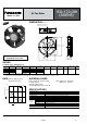
Datasheet


METHOD OF SELECTING FAN MOTOR
FAN MOTOR SERIES/PARALLEL OPERATION
When selecting a fan motor, for normal
use the following method is used.
1) Determine the amount of heat
generated inside the equipment.
2) Decide the permissible temperature
rise inside the equipment.
3) Calculate the volume of air necessary
from Equation (1).
Equation (1)
where
Q: Air volume (m
3
/min.)
H: Heat generated (kW)
T
1: Inlet air temperature(°C)
T
2: Exhaust air temperature(°C)
∆T: Temperature rise(°C)
4) Determine the system impedance of
the equipment by means of Equation (2).
For the flow of air to the equipment, there
is a loss of pressure due to the resistance
to the flow of air from the components
inside the equipment. This loss varies in
accordance with the flow of air. This is
referred to as the system impedance.
∆P=KQ
n
.........Equation (2)
where
∆P: Pressure drop(Pa{mmH
2O})
K: Constant determined for each
equipment
Q: Air volume (m
3
/min.)
n: Coefficient determined by air flow
In this equation, it is generally considered
that n = 2.
Also, it is difficult to calculate the value of
K, since there is no good method other
than an actual test measurement with the
equipment.
Example:
When the heat generated is 100 W with
∆T = 10°C 50°F, the following is the
result.
The intersection of the air volume/static
pressure characteristic curve with the
system impedance curve is called the
operating point. This shows the condition
with the fan motor operating.
In actuality, the system impedance is
approximately assumed, a fan motor is
decided from the catalogue, the
temperature difference “∆T” and air
volume “Q” are measured, and from this
data the fan is judged as suitable or not
as the ordinary method. If the
temperature difference “∆T” is high
indicating the air volume “Q” is not
satisfactory, because the system
impedance is higher than the assumed
value, a change should be made to a fan
motor with a greater air volume.
Fan motor
H
T
2 T1
Heat
generating
section
Equipment
Air volume/static pressure
characteristic curve
Static pressure (Pa{mmH2O})
System impedance
curve
Operating point
0.5
∆P
Air volume (m
3
/min.)
When one fan motor does not satisfy a
sufficient cooling capacity;
Series operation: Higher pressure
characteristic obtained. (Nearly double)
Parallel operation: Larger airflow
characteristic obtained. (Nearly double)
1. In case of series operation
• In case of high system impedance,
static pressure rises.
• In case of low system impedance,
airflow slightly increases.
2. In case of parallel operation
• In case of low system impedance,
airflow increases.
• In case of high system impedance,
pressure slightly rises.
High system
impedance
Static pressure (Pa)
Low system
impedance
Airflow (m
3
/min.)
When two units are put into
series operation
In case of
one unit
Rise in
pressure
Increase in airflow
AIR
High system
impedance
Low system
impedance
When two units are put into
parallel operation
In case
of one unit
Static pressure (Pa)
Airflow (m
3
/min.)
Rise in
pressure
Increase in airflow
AIR
AIR
Technical Information
02/2006
16