ounter c ic n o r t c le e An advanced ns. io t a c li p p a ’s y da perfect for to nd a e p y t it ig -d he 4 Introducing t unter. o c ic n o r t c le 6-digit type e Matsushita Electronic Counter LC4H is the worldwide brand name of automation products.
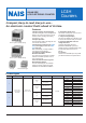
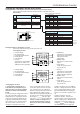
LC4H Counters DIN 48 SIZE LCD ELECTRONIC COUNTER Compact, Easy-to-read, Easy-to-use... An electronic counter that’s ahead of its time. Features AEL51 systems (4-digit display) AEL53 systems (6-digit display) Pin type 1. Bright and Easy-to-Read Display A brand new bright 2-color backlight LCD display. The easy-to-read screen in any location makes checking and setting procedures a cinch. 2. Simple Operation Seesaw buttons make operating the unit even easier than before. 3. Short Body of only 64.5 mm 2.
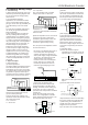
LC4H Electronic Counter Part names DIP switches COUNTER LC4H Counter display 2 3 4 5 6 7 8 ON 1 Controlled output indicator Set value display OP. RST LOCK Reset indicator Lock indicator RESET UP Up keys Reset switch LOCK Down keys DOWN Lock switch (Same for screw-down terminal type) DIP switches COUNTER LC4H Counter display 2 3 4 5 6 7 8 ON 1 Controlled output indicator Set value display Reset indicator OP.
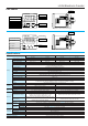
LC4H Electronic Counter Dimensions (units: mm inch) Screw-down terminal type (embedded installation) • LC4H electrical counter 5.5 .217 48 1.890 C OU N T E R Pin type (embedded installation/ front panel installation) 70.1 2.760 55.6 2.189 5.5 .217 64.5 2.539 LC4H (44.5 (1.752 48 1.890 (44.5 (1.752 UP RESET LOCK DOWN 7.5 .295 7.5 .295 Screw-down terminal type (embedded installation) 5.5 .216 48 1.890 COUNTER Pin type (embedded installation/ front panel installation) 70.1 2.760 55.6 2.
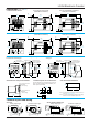
LC4H Electronic Counter Setting the operation mode and counter Setting procedure 1) Setting the operation mode (input mode and output mode) Set the input and output modes with the DIP switches on the side of the unit. DIP switches Table 1: Setting the output mode 1 2 3 4 5 6 7 8 Item DIP switch OFF ON Operation mode Refer to table 1 Minimum reset input signal width Maximum counter setting Input mode 20 ms 30 Hz DIP switch No.
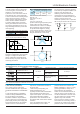
LC4H Electronic Counter Operation mode 1. Input mode For the input mode, you can choose one of the following five modes • Addition • Subtraction UP DOWN • Directive DIR • Independent IND • Phase Input mode PHASE Operation IN1 or IN2 works as an input block (gate) for the other input. *Minimum input signal width: 16.7 ms; 5 kHz: 0.1 ms • Example where IN1 is the count input and IN2 is the input block (gate).
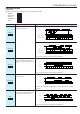
LC4H Electronic Counter 2. Output mode For the operation mode, you can choose one of the following seven modes • Maintain output/hold count HOLD-A • Maintain output/over count I HOLD-B • Maintain output/over count II HOLD-C • One shot/over count SHOT-A • One shot/recount I SHOT-B • One shot/recount II SHOT-C • One shot/hold count SHOT-D Operation mode Maintain output Hold count HOLD-A Operation Output control is maintained after count-up completion and until resetting.
LC4H Electronic Counter Precautions during usage 1. Terminal wiring 1) When wiring the terminals, refer to the terminal layout and wiring diagrams and be sure to perform the wiring properly without errors. 2) For embedded installation applications, the screw-down terminal type is recommended. When using the pin type, use the 11P cap (ATA4861). Do not solder directly to the unit’s round pins. For front panel installation applications, use the 11-pin type DIN rail terminal block (ATC18004).
LC4H Electronic Counter 3. Conditions of usage 1) Avoid locations subject to flammable or corrosive gases, excessive dust, oil, vibrations, or excessive shocks. 2) Since the cover of the unit is made of polycarbonate resin, avoid contact with or use in environments containing methyl alcohol, benzene, thinners, and other organic solvents; and ammonia, caustic sodas, and other alkaline substances. 3) If power supply surges exceed the values given below, the internal circuits may become damaged.
LC4H Electronic Counter INSTALLATIONS 1. Surface mount 1) Use the pin type timer. 2) Put the terminal socket on the board directly or put it on the DIN rail (Fig. 1) 3) Insert the timer into the terminal socket and fix it with clip. (Fig. 2) 4) On DIN rail mounting, mount the timer on the DIN rail tightly. (Fig. 1) 3) a When the water-protected type is used, comfirm the conditions with which timer with rubber gasket and panel are attached tightly.
ACCESSORIES Type mm inch Appearance Terminal wiring (TOP VIEW) Dimensions Mounting hole dimensions • DIN rail socket (11 pin) 11-M3.5×7.5 11-M.138×.295 4.5 .177 hgfe d 51 2.008 2-M4 screw holes UP LC4H (11 pin) 78.0 3.071 71.0 2.795 5.5 .217 40.0 1.575 51.0 2.008 ATC18004 35.6 1.402 2-φ 4.5 2-φ .177 31.0 1.220 71.0 2.795 i c jkab Note: Terminal No. on the main body are identifical to those on the terminal socket. 40±0.2 1.575±.008 Note: Terminal No.