
Datasheet


10
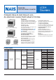
LC4H Electronic Counter
INSTALLATIONS
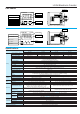
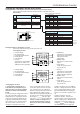
1. Surface mount
1) Use the pin type timer.
2) Put the terminal socket on the board
directly or put it on the DIN rail (Fig. 1)
3) Insert the timer into the terminal
socket and fix it with clip. (Fig. 2)
4) On DIN rail mounting, mount the timer
on the DIN rail tightly.
5) Pin type is connected with terminal
socket ATC18004.
6) DIN rail (AT8-DLA1) is also available
(1m).
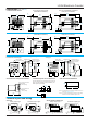
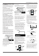
2. Flush mount
1) Use the built-in screw terminal type for
flush mount. (Mounting frame and rubber
gasket are provided when timer is
shipped.)
When the pin type is used, accessories
(AT8-DA4 and ATC18002) are required.
2) Insert the timer into the panel cut and
slide the mounting frame from the back.
Push the mounting frame over the timer
to tighten the screw. Fasten in place with
the screws provided.
3) When the water-protected type is
used, comfirm the conditions with which
timer with rubber gasket and panel are
attached tightly.
Mounting without panel cover and
rubber gasket will be less water-
registant.
4) Loosen the screws on the mounting
frame, spread the edge of frame and
remove it.
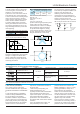
A=(48×n–2.5) (mm)
A=(1.890×n–2.5) inch
If six or more units are to be mounted,
measure the actual dimensions and cut
the panel accordingly.
When lining up
the timers
horizontally, set
the frames in
such a position
so the formed
spring areas are
at the top and
bottom.
When lining up the
timers vertically, set
the frames in such a
position as the formed
spring areas are at the
right and left.
5) Refer to the terminal wiring diagram,
wire the terminals correctly.
6) Panel cutout dimensions
The standard panel cutout dimensions
are shown below. (Panel thickness: 1 to
5mm .039 to .197 inch)
7) Although the timers can be mounted
adjacent to each other, it is
recommended to arrange the mounting
holes as shown in the figure to facilitate
attaching and
detaching the
mounting frame.
When the front
protective cover is
used, cut a hole using these dimensions.
8) Adjacent mounting of PM4H timers
can be accomplished. The front
protective cover
cannot be used for
this type of
mounting. (panel
thickness: 1 to
5mm .039 to .197
inch)
The standard
dimension for A
when n units (n
<
=
5)
are mounted
adjacently.
a
b
+0.6
0
+.024
0
(Fig. 1) (Fig. 2)
Terminal socket
DIN rail
Rubber
gasket
Panel cover Mounting flame
PUSH
Screw
b
a
a
45
+
1.772
+.024
0
0.6
0
45
+0.6
0
1.772
+.024
0
45
+0.6
0
1.772
+.024
0
45
+0.6
0
1.772
+.024
0
80 3.150
A
45
+0.6
0
1.772
+.024
0