
Datasheet


8
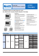
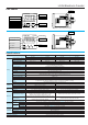
LC4H Electronic Counter
Precautions during usage
1. Terminal wiring
1) When wiring the terminals, refer to the
terminal layout and wiring diagrams and
be sure to perform the wiring properly
without errors.
2) For embedded installation
applications, the screw-down terminal
type is recommended. When using the
pin type, use the 11P cap (ATA4861). Do
not solder directly to the unit’s round
pins.
For front panel installation applications,
use the 11-pin type DIN rail terminal
block (ATC18004).
3) After turning the unit off, make sure
that any resulting induced voltage or
residual voltage is not applied to power
supply terminals 2 through 10 (pin type)
or 1 and 2 (screw-down terminal type). (If
the power supply wire is wired parallel to
the high voltage wire or power wire, an
induced voltage may be generated
between the power supply terminals.)
4) Have the power supply voltage pass
through a switch or relay so that it is
applied at one time. If the power supply
is applied gradually, the counting may
malfunction regardless of the settings,
the power supply reset may not function,
or other such unpredictable occurrence
may result.
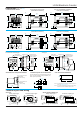
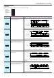
2. Input and output
1) Signal input type
(1) Contact point input
Use highly reliable metal plated contacts.
Since the contact point’s bounce time
leads directly to error in the count value,
use contacts with as short a bounce time
as possible. In general, select Input 1
and Input 2 to have a maximum counting
speed of 30 Hz and to be reset with a
minimum input signal width of 20 ms.
(2) Non-contact point input
Connect with an open collector. Use
transistors whose characteristics satisfy
the criteria given below.
V
CEO = 20 V min.
I
C = 20 mA min.
ICBO = 6µA max.
Also, use transistors with a residual
voltage of less than 2 V when the
transistor is on.
* The short-circuit impedance should be
less than 1 kW.
[When the impedance is 0 W, the current
coming from the input 1 and input 2
terminals is approximately 12 mA, and
from the reset input and lock input
terminals is approximately 1.5 mA.]
Also, the open-circuit impedance should
be more than 100 kΩ.
* As shown in the diagram below, from a
non-contact point circuit (proximity
switches, photoelectric switches, etc.)
with a power supply voltage of between
12 and 40 V, the signal can be input
without using an open collector
transistor. In the case of the diagram
below, when the non-contact point
transistor Q switches from off to on
(when the signal voltage goes from
high to low), the signal is input.
2) The input mode and output mode
change depending on the DIP switch
settings. Therefore, before making any
connections, be sure to confirm the
operation mode and operation conditions
currently set.
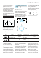
3) For the power supply of the input
device, use a single-phase or double-
phase insulated power transformer. The
second-phase side must not be
grounded.
4) Since the power supply circuitry does
not contain a transformer, be aware that
it is not possible for simultaneous input
from an input contact point or transistor
to a LC4H counter with independent
power supply operation.
5) The input signal is applied by the
shorting of each input terminal with the
common terminal (terminal 3 for pin
types, and terminal 6 for screw-down
terminal types). Never connect other
terminals or voltages higher than DC 40
V, because it may destroy the internal
circuitry.
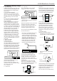
6) Transistor output
(1) Since the transistor output is
insulated from the internal circuitry by
a photocoupler, it can be used as an
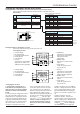
Pin type
Screw terminal type
3 4 5 6 7
6 7 8 9 10
Reset input
Input 1
Input 2
Lock
input
Pin type
Screw terminal type
3
4 5 6 7
6 7 8 9
10
Reset input
DC12 to 40V
Q
(The above example is for reset input)
Load
Load’s power supply
LC4H counter
As NPN output
Load
Load’s power supply
LC4H counter
As PNP output
LC4H counter
Input
terminals
Circuit
Rectifier circuits
Power
supply
Insulated transformer
is necessary
Load’s
power supply
Inductive load
LC4H counter
Diode rating:
I
F (forward current): 1 A
V
R (reverse voltage): 600 V
Pin type
Screw terminal type
3 4 5 6 7
6 7 8 9 10
Reset input
Input 1
Input 2
Lock
input
Power
supply
LC4H counter
LC4H counter
Input
terminals
Input
terminals
Input contact
point or transistor
NPN output or PNP (equal value)
output.
(2) Use the diode connected to the
output transistor’s collector for absorbing
the reverse voltage from induced loads.
7) When wiring, use shielded wires or
metallic wire tubes, and keep the wire
lengths as short as possible.
8) For the load of the controlled output,