Operating Instructions Multi-format Live Switcher AV-HS400AN Model No.
Safety precautions CAUTION: CAUTION TO REDUCE THE RISK OF FIRE OR SHOCK HAZARD AND ANNOYING INTERFERENCE, USE THE RECOMMENDED ACCESSORIES ONLY. RISK OF ELECTRIC SHOCK DO NOT OPEN CAUTION: TO REDUCE THE RISK OF ELECTRIC SHOCK, DO NOT REMOVE COVER (OR BACK). NO USER SERVICEABLE PARTS INSIDE. REFER TO SERVICING TO QUALIFIED SERVICE PERSONNEL. FCC Note: This equipment has been tested and found to comply with the limits for a class A digital device, pursuant to Part 15 of the FCC Rules.
Safety precautions IMPORTANT SAFETY INSTRUCTIONS Read these operating instructions carefully before using the unit. Follow the safety instructions on the unit and the applicable safety instructions listed below. Keep these operating instructions handy for future reference. 10) Protect the power cord form being walked on or pinched particularly at plugs, convenience receptacles, and the point where they exit from the apparatus. 1) Read these instructions. 2) Keep these instructions. 3) Heed all warnings.
Contents 3-4. PinP (picture in picture)....................................39 3-4-1. Selecting the PinP material.......................39 3-4-2. PinP transitions..........................................39 3-4-3. PinP preview..............................................39 3-4-4. PinP adjustments.......................................40 3-4-5. PinP decorations........................................41 3-4-6. Trimming settings.......................................42 Description.............................
Contents 4. Input/output signal settings............... 61 5. System settings................................... 83 4-1. S etting the SDI input signals and analog input signals..............................................................61 4-1-1. Setting the frame synchronizer..................61 4-1-2. Setting the input mode...............................62 4-1-3. Setting the analog input gain.....................63 4-1-4. S etting the analog composite input signals..................................
Description This is a 1 ME digital video switcher which supports a multiple number of HD and SD formats. Despite its compact dimensions, the video switcher comes standard with 4 input connectors and can support 8 input connectors when an option board is used. It also has a multi view display function that allows split-screen display with up to 10 screens.
Precautions for use Handle carefully. Do not drop the product, or subject it to strong shock or vibration. Do not carry or move the product by the fader lever. This is important to prevent trouble. Use the product in an ambient temperature of 32 °F to 104 °F (0 °C to 40 °C). Avoid using the product at a cold place below 32 °F (0 °C) or at a hot place above 104 °F (40 °C) because extremely low or high temperature will adversely affect the parts inside.
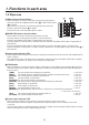
1. Functions in each area 1-1.
1. Functions in each area 1-2. Crosspoint area F1 F2 F3 F4 F5 AMB:FILL / GRN:SOURCE KEY AUX PGM/A 1 DSK PinP AUX BUS DELEGATION 2 3 AUX 4 CLN 5 PVW AUX SOURCE PGM 6 7 1 2 USER 8 9 10 PST/B 3 PGM/A bus crosspoint buttons [PGM/A 1 to 10] These are used to select the PGM/A bus video signals. In the case of the flip-flop system, the main line video (PGM) signals are always selected.
1. Functions in each area 1-3. Wipe area 8 Wipe pattern selector buttons These 12 buttons are used to select the corresponding wipe patterns while the indicator of the [BKGD PATT] button (9) or [KEY PATT] button (9) is lighted. They are used to select the corresponding setting menus when the indicator of the FUNC button (;) is lighted. The indicator of the selected button lights in amber.
1. Functions in each area 1-4. User button area 1 2 USER = User buttons [USER 1, USER 2] These are used to allocate some functions of the menu settings to the USER 1 button and USER 2 button. See 5-3-1.
1. Functions in each area 1-5. Transition area 7 8 PinP IN/OUT 10 11 12 MEMORY KEY PATT XPT SYSTEM WIPE PATTERN / FUNCTION FUNC N/R R WIPE DIRECTION MIX 9 DSK WIPE FTB ON BKGD KEY PinP MIX WIPE CUT DSK AUTO > [BKGD] button This executes the background transition when the [AUTO] button (D) or fader lever (J) has been operated. When the [BKGD] button is pressed and it is selected, its indicator lights in amber.
1. Functions in each area D [AUTO] button This is used to automatically execute transitions (auto transition) using the transition time which has been set. During auto transition its indicator lights in amber. When the button is pressed again during auto transition, the auto transition operation is suspended, and the indicator lights in green. When it is pressed again while auto transition is suspended, the remaining transition is executed. The indicator goes off when auto transition is completed.
1. Functions in each area 1-6. LCD menu area L LCD The setting menus are displayed on the LCD. When the [FUNC] button (;) is pressed and its indicator is lighted and then one of the wipe pattern selector buttons (8) is pressed, the setting menu is displayed. When the buttons listed below are double-clicked, the specified menu is selected. (The menu delegation function) The operation corresponding to the button pressed is also executed.
1. Functions in each area 1-7. Positioner area N Positioner [X/Y] These are used when performing the settings below. PinP position setting Z Wipe start position setting (WIPE, SQ #5) Camera control POSITIONER Flying key position setting Chroma key area In each case, the settings take effect only when the following menu items have been selected. The center values of the positioner are set during the time it takes for the unit to start up after its power is turned on.
1. Functions in each area 1-8. SD memory card area P SD memory card slot The SD memory card (sold separately) is inserted into this slot. SD Logo is a trademark. Q SD memory card access LED This LED lights while the data on the SD memory card is being accessed. Do not turn off the unit’s power or eject the SD memory card while the access LED is lighted. Doing so can damage the data on the SD memory card.
1. Functions in each area 1-9.
1. Functions in each area Y LAN connector [LAN] (RJ-45) (10BASE-T) Z RS-422 interface connector [RS-422] (D-sub 9-pin, female, inch screw) For details on connection, refer to “6. External interfaces”. [ Tally output connector [TALLY] (D-sub 15-pin, male, inch screw) For details on connection, refer to “6. External interfaces”. \ GPI input connector [GPI] (3.5 mm diameter stereo mini jack) For details on connection, refer to “6. External interfaces”.
2. System 2-1.
2. System 2-2.
2.
3. Basic operations 3-1. Background transition 3-1-1. Selecting the bus Press the crosspoint buttons to select the material which will be targeted for the background transition. By pressing these buttons, the signals are selected, and the indicators of the selected buttons light. The color in which the button indicators light differs depending on the operation status. Lighting in red: When the selected input signals are output to PGM. (However, the indicator lights in amber during FTB operations.
3. Basic operations 3-1-3. Selecting the transition mode Press the [BKGD] button in the transition area so that its indicator lights in amber. When the [BKGD] button and [KEY] button are pressed at the same time, both buttons are selected. Use the [MIX] and [WIPE] buttons in the transition area to select the background transition mode. The indicator of the selected button lights in amber. 3-1-4. Manual transition (using the fader lever) Operate the fader lever to execute transitions manually.
3. Basic operations 3-2. Wipe 3-2-1. Selecting the wipe pattern PAGE 1 2 TIME 4 3 WIPE COLOR 5 KEY 7 6 CHR KEY DSK 10 3D BKGD PATT 9 PinP IN/OUT 11 MEMORY SQ SL ON FREEZE 8 WIPE KEY PATT 12 XPT SYSTEM WIPE PATTERN / FUNCTION FUNC The wipe patterns which are allocated to the 12 wipe pattern buttons are used as the basis for wiping, and each button has four pages — wipe, squeeze, slide and 3D — of patterns. (Refer to the table of wipe patterns.
3. Basic operations 3-2-2. Selecting the wipe direction Operate the wipe direction selector buttons to select the wipe direction for the background transition. (The key transitions are set by the menu. The direction which is set here will not be reflected. See 3-3-3.) When the [R] indicator is off: Wiping proceeds in the normal direction. When the [R] indicator is lighted: Wiping proceeds in the reverse direction. When the [N/R] indicator is lighted: ! . 2 .
3. Basic operations 3-2-4. Setting the wipe start position Any start position can be set for wipe pattern WIPE and SQ #5. The start position has one set of values for a background pattern and another set for a key pattern. 1 Press the [FUNC] button to light its indicator, and press the [WIPE] button to display the WIPE menu. 2 Turn [F1] to display the WIPEPos sub menu or the SQPos sub menu.
3. Basic operations 3-2-5. Modifying wipe Setting the lighting effect Lighting effects can be added when the following wipe patterns have been selected: 3D page: #1, #3, #7, #9 1 Press the [FUNC] button to light its indicator, and press the [WIPE] button to display the WIPE menu. 2 Turn [F1] to display the Modify sub menu.
3. Basic operations 3-3. Key This operation combines the background image with another image. The key definition can be adjusted, and an edge can be added to the combined image. Also available as materials besides KEY for combining with the background image are PinP (picture in picture) and DSK (downstream key). The figure below shows their priorities. Background image KEY PinP DSK How key combinations work is shown in the figure below.
3. Basic operations 3-3-1. Selecting the key type 1 Press the [FUNC] button to light its indicator, and press the [KEY] button to display the KEY menu. 2 Turn [F1] to display the KEY sub menu. 3 Turn [F2] to select the Type item.
3. Basic operations 3-3-2. Selecting the key material Selecting the key fill and key source signals Press the KEY button in the AUX bus selection area, and switch the selection of the key fill signal (indicator lights in amber) and key source signal (indicator lights in green). With the indicator of the KEY button lighted in amber, press one of the AUX bus crosspoint buttons 1 to 10 to select the key fill signal.
3. Basic operations 3-3-3. Key transitions MIX WIPE 1 Select key in the transition mode. Press the [KEY] button in the transition area to light its indicator. To execute a background transition and key transition at the same time, press the [BKGD] button and [KEY] button together to turn on both indicators. ON BKGD KEY MIX WIPE 2 Select the transition type. Use the [MIX] button or [WIPE] button in the transition area to select the key transition mode.
3. Basic operations 5 Execute the transition. Press the [AUTO] button to execute the transition automatically for the transition time which has been set. Alternatively, execute the transition manually by operating the fader lever. When the KEYAuto function has been assigned to the [FTB] button, the transition will be executed automatically for the transition time which has been set when the [FTB] key is pressed no matter which transition mode has been selected.
3. Basic operations 3-3-6. Adjusting the chroma key These steps are taken to adjust the chroma key definition. Before proceeding with the adjustments, select “Chroma” as the Type item setting in “3-3-1. Selecting the key type.” Chroma Hue Radius Sat Radius The signal for the chroma key is created using a specific color tone as a reference.
3. Basic operations Adjusting the chroma key 1 Press the [FUNC] button to light its indicator, and press the [CHR KEY] button to display the CHR KEY menu. 2 Turn [F1] to display the Adjust1 sub menu, and turn [F2] to [F5] to set the items.
3. Basic operations Making other adjustments Perform the key density and key invert settings. 1 Press the [FUNC] button to light its indicator, and press the [KEY] button to display the KEY menu. 2 Turn [F1] to display the Adjust sub menu.
3. Basic operations 3-3-7. Key decorations A border, shadow or other edge can be added to the key. Setting the key edge 1 Press the [FUNC] button to light its indicator, and press the [KEY] button to display the KEY menu.
3. Basic operations 3-3-8. Masking the key signals These steps are taken to mask the key signals using the mask signal of the box pattern. 1 Press the [FUNC] button to light its indicator, and press the [KEY] button to display the KEY menu. 2 Turn [F1] to display the Mask sub menu.
3. Basic operations 3-3-9. Flying key Using DVE effects, this key enables the key signals that have been input to be moved, expanded or contracted. In order for the flying key to take effect, select SL #5 as the key transition. When the key transition is executed, the keys are combined by the key signals set using the flying key menu. (The transition effect is fixed at MIX.) Since the flying key uses DVE effects, the image is delayed by one frame.
3. Basic operations 3-4. PinP (picture in picture) Another image can be combined with the background image. 3-4-1. Selecting the PinP material Press the [PinP] button among the AUX bus selector buttons to light its indicator, and press one of the AUX bus crosspoint buttons 1 to 10 to select the PinP signal. The indicators of both the [PinP] button and the selected AUX bus crosspoint button light in amber. (They light in red if the selected signal is being output to the PGM connector.
3. Basic operations 3-4-4. PinP adjustments Adjusting the PinP position and size While the PinP menu is selected, adjust the X and Y coordinates using the positioner in the positioner area, and adjust the size using the rotary encoder [Z]. Alternatively, the settings can be performed on the menus. 1 Press the [FUNC] button to light its indicator, and press the [PinP] button to display the PinP menu. 2 Turn [F1] to display the Position sub menu.
3. Basic operations 3-4-5. PinP decorations A border or soft effect can be added to PinP. 1 Press the [FUNC] button to light its indicator, and press the [PinP] button to display the PinP menu. 2 Turn [F1] to display the Border sub menu.
3. Basic operations 3-4-6. Trimming settings 1 Press the [FUNC] button to light its indicator, and press the [PinP] button to display the PinP menu. 2 Turn [F1] to display the Trim sub menu.
3. Basic operations 3-5. DSK (downstream key) Characters or other images can be combined with the background image. 3-5-1. Selecting the DSK type 1 Press the [FUNC] button to light its indicator, and press the [DSK] button to display the DSK menu. 2 Turn [F1] to display the DSK sub menu. 3 Turn [F2] to select the Type item.
3. Basic operations 3-5-2. Selecting the DSK material Selecting the DSK fill signal and DSK source signal Press the [DSK] button in the AUX bus selection area to switch the selection of the DSK fill signal (indicator lights in amber) and DSK source signal (indicator lights in green). AMB:FILL / GRN:SOURCE While the indicator of the [DSK] button is lighted in amber, press one of the AUX bus crosspoint buttons 1 to 10 to select the DSK fill signal.
3. Basic operations 3-5-3. DSK transitions 1 Set the duration of the transition. On the TIME menu, turn [F1] to display the DSK sub menu. As with a background transition, set the transition time. 2 When the [DSK] button in the transition area is pressed, the DSK image is combined (fade-in) for the transition time which was set. During fade-in, the indicator of the [DSK] button blinks in red, and it lights in red when the transition (fade-in) is completed.
3. Basic operations 3-5-6. DSK decorations A border, shadow or other type of edge can be added to DSK. Setting the edge 1 Press the [FUNC] button to light its indicator, and press the [DSK] button to display the DSK menu.
3. Basic operations 3-5-7. Masking the DSK signals These steps are taken to mask the DSK signals using the mask signal of the box pattern. 1 Press the [FUNC] button to light its indicator, and press the [DSK] button to display the DSK menu. 2 Turn [F1] to display the Mask sub menu.
3. Basic operations 3-6. FTB (fade to black) The user can fade out from a program image to the black screen or fade in to a program image from a black screen. 1 Set the duration of the transition. On the TIME menu, turn [F1] to display the FTB sub menu. As with a background transition, set the transition time. 2 When the [FTB] button in the transition area is pressed, fade-out to the black screen is initiated.
3. Basic operations 3-7. Internal color signals 3-7-1. Setting the color background The color background to be used by the bus can be set. Two methods are available: under one method the Hue (hue), Sat (color saturation) and Lum (luminance) are set, and under the other the 8 preset colors (white, yellow, cyan, green, magenta, red, blue and black) are called. The Hue, Sat and Lum of the called colors can also be adjusted.
3. Basic operations 3-8. Freezing the input signals The input signals can be frozen and used. If any of the input signals has been frozen, the freeze status indicator LED lights. While signals are frozen, the tally signals of the corresponding input will not be output. 3-8-1. Displaying the freeze status 1 Press the [FUNC] button to light its indicator, and press the [FREEZE] button to display the Freeze menu. 2 Turn [F1] to display the Status sub menu.
3. Basic operations 3-9. Switching the AUX output The user can switch the AUX output signals. The signals of any of the AUX bus crosspoint button 1 to 10, PGM (program) signals, PVW (preview) signals or CLN (clean) signals can be selected for output to the AUX bus. [PGM]: The PGM signals are output to the AUX bus. [PVW]: The PVW signals are output to the AUX bus. [CLN]: The clean signals (images whose DSK signals have been removed from the PGM signals) are output to the AUX bus.
3. Basic operations 3-10. Preset memory Up to 10 panel settings can be stored in this memory. The table below lists the settings which are stored.
3.
3. Basic operations STORE: This is used to store the panel settings in the preset memory. 1 Press the [FUNC] button to light its indicator, and press the [MEMORY] button to display the MEMORY menu. 2 Turn [F1] to display the PSMEM sub menu. 3 Turn [F2], select “Store” using the Mode item, turn [F3], and set the preset memory number using the NO.Sel item. 4 Press the [F5] switch (Exec) to store the settings.
3. Basic operations 3-11. Frame memories Still images can be stored in the unit’s two internal frame memories for use. The still images are transferred to the frame memories through the AUX bus and an SD memory card. Conversely, the images in the frame memories can be transferred to an SD memory card. Images in the frame memories can be used as bus images by assigning FMEM1 and FMEM2 using the crosspoint assignment function.
3. Basic operations 3-12. SD memory cards The unit’s frame memory data and system data can be stored on SD memory cards. Conversely, this data can be loaded from the SD memory cards to the unit. Frame memory data (still image data): The unit supports 24-bit (uncompressed) BMP (bitmap) and JPEG (baseline) is the only file formats. JPEG format files can be loaded, but they become BMP format files when they are stored from the unit to the SD memory card.
3. Basic operations 3-12-1. Initializing the SD memory cards In order for an SD memory card to be used in the unit, it must first be initialized by the unit. Initializing the SD memory card formats it (in compliance with the SD standard) and creates the dedicated directory. (All files saved on the SD memory card will be erased.) 1 Insert the SD memory card into the unit’s SD memory card slot. 2 Press the [FUNC] button to light its indicator, and press the [MEMORY] button to display the MEMORY menu.
3. Basic operations 3-12-2. Saving data on SD memory cards 1 Insert the SD memory card which has been initialized by the unit, into the SD memory card slot. 2 On the MEMORY menu, turn [F1] to display the SDCard sub menu. 3 Turn [F2] to select “Save” using the Mode item, and then press the [F2] switch.
3. Basic operations 3-12-3. Loading data from SD memory cards 1 Insert the SD memory card on which the data is stored into the SD memory card slot. Load the file after its data has been stored in the each folder. Data stored in other folders will not be recognized by the unit. System data: “HS400/SYSTEM” folder Still image data: “HS400/IMAGE” folder 2 On the MEMORY menu, turn [F1] to display the SDCard sub menu. 3 Turn [F2] to select “Load” using the Mode item, and then press the [F2] switch.
3. Basic operations 3-12-4. Deleting files on SD memory cards 1 Insert the SD memory card on which the data is stored into the SD memory card slot. 2 On the MEMORY menu, turn [F1] to display the SDCard sub menu. 3 Turn [F2] to select “Delete” using the Mode item, and then press the [F2] switch.
4. Input/output signal settings 4-1. Setting the SDI input signals and analog input signals The user can set the SDI input signals and analog input signals. IN5 to IN8 can be set only when one of the following optional boards has been connected: SDI input board Analog input board Analog composite input board 4-1-1. Setting the frame synchronizer The frame synchronizer can be set to On or Off for each input. The DVI input (option) frame synchronizer is permanently On.
4. Input/output signal settings 4-1-2. Setting the input mode The mode can be set for each input only when HD has been selected as the system format. When SD is selected as the system format, the input mode is always the same as Normal. Normal: Input signals in conformity with the system format take effect. D by D: When SD signals with the same frame rate as the system format have been input, they are input on a dot by dot (1 magnification) basis with no up-conversion.
4. Input/output signal settings 4-1-3. Setting the analog input gain When the analog input board (option) has been connected, the gain of the input signals can be set. Alternatively, when the analog composite input board (option) has been connected, the gain of the Y signals can be set. The setting range is ±30 steps, and the gain changes by approximately ±2 dB. The amount of change in the gain when it is changed by one step is not fixed.
4. Input/output signal settings 4-2. Setting the up-converter (option) Select the settings for the up-converter that is built into the optional boards listed below. SDI input board Analog input board Analog composite input board 1 Press the [FUNC] button to light its indicator, and press the [IN/OUT] button to display the IN/OUT menu. 2 Turn [F1] to display the UpConvt sub menu. An asterisk (]) appears at the left of the parameter currently selected.
4. Input/output signal settings 4-3. Setting the DVI input signals (option) 4-3-1. Setting the DVI input signals The user can set the DVI input signals when the DVI input board (option) has been connected. Signals with the following resolutions can be input. If signals with any other resolution or frequency are input, the picture will turn black.
4. Input/output signal settings DVI format XGA 1024768 Mode HD/1080i 1920 1080 HD/720P 1280 720 Fit-V SD/PAL 720 576 720 480 SD/NTSC 720 480 720 576 Fit-H Full Fit-V 576 675 675 576 480 720 720 480 SXGA 12801024 Fit-H Full WXGA 1280768 720 480 720 576 Fit-V Fit-H Full : Black images are inserted here.
4. Input/output signal settings 4-3-2. Adjusting the DVI input signals Adjust the clock/phase and position of the DVI input signals. 1 Press the [FUNC] button to light its indicator, and press the [IN/OUT] button to display the IN/OUT menu. 2 Turn [F1] to display the DVIPhs sub menu.
4. Input/output signal settings 4-4. Setting the output signals 4-4-1. Types of output signals There are five output signal types: PGM, PVW, AUX, MULTI and KEYOUT. Five lines of output signals can be assigned to OUTPUT1 to 6. PGM: This is the main-line output of the switcher; images with wipe, mix, key and other effects added to them are output. PVW: This is the preview output which enables the next operation to be checked in advance. AUX: Signals selected by the AUX bus are output.
4. Input/output signal settings 4-4-2. Assigning the output signals Assign the output signals to OUTPUT1 to 6. 1 Press the [FUNC] button to light its indicator, and press the [IN/OUT] button to display the IN/OUT menu. 2 Turn [F1] to display the Output sub menu. 3 Turn [F2] to select the signal name using the Signal item, and turn [F3] to set the type of output signal using the Output item.
4. Input/output signal settings 4-5. Setting the sync signals The sync signals to be used by the system can be selected. External sync: For synchronization with an external sync signal (gen-lock). The reference input signal is looped through and output. BBST: Black burst signal (vertical phase of 0H) BBAD: Black burst signal ( Vertical phase of 90H when the 59.94i or 59.
4. Input/output signal settings 4-6. Adjusting the output signal phase The phase of the output video signals can be adjusted. 1 Press the [FUNC] button to light its indicator, and press the [IN/OUT] button to display the IN/OUT menu. 2 Turn [F1] to display the OutPhs sub menu.
4. Input/output signal settings REF (System standard) Approx. 0.2H AVDL Range Approx. –0.2H to +0.8H Approx. 0.2H Internal Fixed DL • 1H Output (+1H) Output Phase Variable Range H Phase (–0.5H to +0.5H) + V Phase vertical (100 lines) AVDL Range Internal Fixed DL Approx. -0.7H to +0.3H Shortest Output (+0.5H) Approx. 0.3H +0.5H Output Phase Variable Range H Phase (–0.5H to +0.5H) + V Phase vertical (100 lines) AVDL Range Approx. +0.3H to +1.3H Longest Output (+1.
4. Input/output signal settings Frame synchronizer Input signals FS: On, Off Mode: Normal, UC or D by D (cannot be selected when the system format is 720p) Output signals 1 Video effects DC (Down-converter) Delay: 90H (75H) or 1F See 4-1-1. 2 See 4-11. When the 1080/59.94i format is used: For 1080/50i, 720/59.94p and 720/50p, the delay of “Output signal 2 DC (90H)” is further delayed by +1F.
4. Input/output signal settings (for 1080/59.94i format) (Example 1) Input signals (non-synchronized) F1 F2 Sync signal (Ref) 1F (frame) F1 F2 Output signal 1 Max. 1F F1 F2 Output signal 2 (90H) Max. 1F+90H F1 F2 Output signal 2 (1F) Max. 2F (Example 2) Input signals (non-synchronized) F1 F2 Sync signal (Ref) 1F (frame) F1 F2 Output signal 1 Max. 1F–90H F1 F2 Output signal 2 (90H) Max. 1F F1 Output signal 2 (1F) Max.
4. Input/output signal settings 4-7. Setting the multi view display The input images, program images and preview images can be output side by side on one screen on the external monitor. 4-7-1. Setting the screen layout The multi view display has three display modes: 10-division mode, 4-division mode and 8-division mode. Inputs 1 to 8, frame memory and color background can be assigned to sub screens 1 to 8.
4. Input/output signal settings 1 Press the [FUNC] button to light its indicator, and press the [IN/OUT] button to display the IN/OUT menu. 2 Turn [F1] to display the Multi1 sub menu.
4. Input/output signal settings 4-7-2. Setting the split frame and characters Set the frame, character brightness and background of the split screens to be displayed on the multi view display. 1 Press the [FUNC] button to light its indicator, and press the [IN/OUT] button to display the IN/OUT menu. 2 Turn [F1] to display the Multi2 sub menu.
4. Input/output signal settings 4-7-4. Changing the material names Change the INPUT1 to INPUT8 material names shown on the multi view display. The default settings, preset settings or user settings can be selected for these names. When the preset settings and user settings are established, the “input number : material name” (1 : CAM1, etc.) display format is used. 1 Press the [FUNC] button to light its indicator, and press the [IN/OUT] button to display the IN/OUT menu.
4. Input/output signal settings 4-8. Setting the on-screen display (OSD) The menu screen is superimposed on the preview output or multi view display output for display. 1 Press the [FUNC] button to light its indicator, and press the [IN/OUT] button to display the IN/OUT menu. 2 Turn [F1] to display the OSD sub menu.
4. Input/output signal settings 4-9. Setting the DVI output signals (option) Set the DVI output signals when the DVI/analog output boards (option) have been connected. 1 Press the [FUNC] button to light its indicator, and press the [IN/OUT] button to display the IN/OUT menu. 2 Turn [F1] to display the DVIOut sub menu. An asterisk (]) appears at the left of the parameter currently selected.
4. Input/output signal settings 4-10. Setting the ancillary data In this section, the function for allowing the ancillary data of the SDI input signals to pass through is set. If SD format signals are input while the HD format has been set as the system format, it will not be possible for their ancillary data to be passed through.
4. Input/output signal settings 4-11. Setting the down-converter Select the settings for the down-converter that is built into the SDI output board (option). 1 Press the [FUNC] button to light its indicator, and press the [IN/OUT] button to display the IN/OUT menu. 2 Turn [F1] to display the DownConv sub menu. An asterisk (]) appears at the left of the parameter currently selected.
5. System settings 5-1. Selecting the video format One system (input/output signal) video format can be selected. 1 Press the [FUNC] button to light its indicator, and press the [SYSTEM] button to display the SYSTEM menu. 2 Turn [F1] to display the Format sub menu. 3 Turn [F2], select the format using the Mode item, and press the [F2] switch to enter the selection. An asterisk (]) appears at the left of the format currently selected.
5. System settings 5-2. Setting the crosspoints 5-2-1. Assigning signals to the crosspoints External video input signals and internally generated signals can be assigned to crosspoint buttons 1 to 10. Displaying the assignment statuses 1 Press the [FUNC] button to light its indicator, and press the [XPT] button to display the XPT menu. 2 Turn [F1] to display the XPTStats sub menu. The status of the assignment is displayed. The names of the assigned signals are abbreviated on the display.
5. System settings The table below lists the default settings.
5. System settings 5-3. Button assignments 5-3-1. Setting the user buttons The user can assign several functions which can be set using the menu items into two user buttons (USER 1 and USER 2). The user buttons light in amber when the assigned function is ON and are off when the assigned function is OFF. Each time the user button is pressed, the function setting alternates between ON and OFF. The table below lists the functions which can be assigned to the user buttons.
5. System settings 5-4. Setting the date and time The user can set the date and time to be used as the SD memory card’s time stamp. Be absolutely sure to set them when an SD memory card is to be used. Setting the date 1 Press the [FUNC] button to light its indicator, and press the [SYSTEM] button to display the SYSTEM menu. 2 Turn [F1] to display the Date sub menu. 3 Turn [F2] to set the year using the Year item. 4 Turn [F3] to set the month using the Month item.
5. System settings 5-5. Network settings Proceed with the network settings to perform such tasks as updating the software version via LAN. The network initial setup is: IP address: 192.168.0.10, subnet mask: 255.255.255.0 and gateway: 0.0.0.0 (unused). When using the host computer with settings matching the network setup, it is not necessary to setup via the menu. For the setting to take effect, the system must be rebooted. Turn the system’s power off and then back on.
5. System settings 5-6. Other settings 5-6-1. Setting the LCD backlight The LCD backlight can be set to ON or OFF. 1 Press the [FUNC] button to light its indicator, and press the [SYSTEM] button to display the SYSTEM menu. 2 Turn [F1] to display the System sub menu. 3 Turn [F3], and select On or Off for the backlight using the LCD-BL item.
5. System settings 5-6-4. Setting the GPI The user can set the functions that are to be controlled from the GPI ports and set whether to enable the control. 1 Press the [FUNC] button to light its indicator, and press the [SYSTEM] button to display the SYSTEM menu. 2 Turn [F1] to display the GPI sub menu, and turn [F2] to set the function to be controlled by the GPI port 1 using the GPI1 item.
5. System settings 5-7. Camera control A camera and pan-tilt head can be controlled from this unit. Up to five cameras can be controlled via a controller (AW-RP655N or AW-RP555N) connected to the unit’s RS422 interface connector. The unit can also be connected directly to a pan-tilt head, and the camera and pan-tilt head can be controlled. To control a camera in this way, select “P/TCont” or “P/TDirt” as the Protcol item setting. See 5-6-3.
5. System settings Example of connections (when the unit and a controller are connected) Controllers that can be connected: AW-RP655N, AW-RP555N For details on connecting the pan-tilt heads and controller or connecting the pan-tilt heads and cameras, refer to the operating instructions of each device.
5. System settings Example of connections (when the unit and a pan-tilt head are connected) Pan-tilt heads that can be connected: AW-HE100N, AW-PH400P, AW-PH405N, AW-PH360N Connections for AW-HE100N, AW-PH405N or AW-PH360N Analog component signals (For the connection specifications, refer to the Operating Instructions of the AW-HE100N.
5. System settings Connections for AW-PH400P CONTROL IN IP/RP connector POWER OUTPUTS SLOT2 SLOT1 Y Pb 6 4 INPUTS 5 3 8 6 DVI/ANALOG OUTPUTS Pr 7 5 SLOT2 SLOT1 DVI INPUTS DVI-I DVI-I ON DVI-I OFF SLOT 2 SLOT 2 ~IN Y Pb ANALOG OUTPUTS Y Pr Pb Y Pr ANALOG INPUTS Y Pr Pb Pb Pr SLOT 1 SLOT 1 SDI OUTPUTS 4 PGM 2 OUT 1 3 IN OUT SDI INPUTS IN 2 OUT LAN 1 IN OUT REF RS-422 TALLY GPI IN SIGNAL GND AV-HS400AN AW-PH400P Cable length: Max. 656 ft.
5. System settings Camera control settings 1 Press the [FUNC] button to light its indicator, and press the [SYSTEM] button to display the SYSTEM menu. 2 Turn [F1] to display the CamCTL1 sub menu.
5. System settings 9 Turn [F4] to set the control (panning, tilting, lens focusing and lens zooming) speed using the Speed Item. Fast: Control is exercised at the fastest speed. Middle: Control is exercised at the medium speed. (This cannot be selected for the control of lens focusing or lens zooming.) Slow: Control is exercised at the slowest speed. : When controlling the pan-tilt head’s power to On, turn [F5] to select On, and press the [F5] switch.
5. System settings 5-8. Status displays 5-8-1. Alarm status displays These displays indicate a trouble status (alarm) in the power supply or fan. 1 Press the [FUNC] button to light its indicator, and press the [SYSTEM] button to display the SYSTEM menu. 2 Turn [F1] to display the Alarm sub menu.
5. System settings 5-8-2. Displaying the version information and option information Information on the unit’s software and hardware versions and the statuses of the options are displayed. 1 Press the [FUNC] button to light its indicator, and press the [SYSTEM] button to display the SYSTEM menu. 2 Turn [F1] to display the MainVer sub menu. 3 Turn [F2] to select the item whose version is to be displayed using the Select item. 4 The version information is displayed in the Version item.
5. System settings 5-9. Initialization Initialization returns the set data to the factory shipment status. (The network settings and the date and time settings are not initialized.) 1 Press the [FUNC] button to light its indicator, and then press the [SYSTEM] button to display the SYSTEM menu. 2 Turn [F1] to display the Initial sub menu.
6. External interfaces This unit comes with RS-422, GPI and tally connectors to serve as external interfaces. 6-1. RS-422 connector This enables the unit to be controlled by an external device. Use it with the settings below. (D-sub 9-pin, female, inch screw) Baud rate: 38400 bps Parity: Stop bit: ODD 1 bit 5 4 9 3 8 2 7 1 6 Pin assignment Pin No.
6. External interfaces 6-2. GPI connector These connectors enable the unit to be controlled from an external source. Signals are input using contacts. The following types of control are exercised using the contacts as triggers. Use stereo mini plugs with a 3.5 mm diameter for connection to the unit.
6. External interfaces 6-3. Tally connector The tally connector comes with tally output, output enable, power supply or fan alarm output pins. The output signals from the tally output pins are for lighting the tally lamps, and these outputs are open collector outputs. 1 2 3 4 5 6 7 8 (D-sub 15-pin, male, inch screw) 9 10 11 12 13 14 15 Pin assignment Pin No.
7. Image transmission functions This unit comes with a function for transmitting still images from the host computer to the unit via LAN and a function for importing still images from the unit into the host computer. The image transmission software must be installed in the host computer from the CD-ROM supplied in order to use these functions. For details on installation, refer to “How to install the software”.
7. Image transmission functions How to install the software This section describes how to install the image transmission software (HS400 Tool). Windows XP is used as the host computer’s operating system in the example given here. 1. Insert the CD-ROM supplied with the unit into the CD-ROM drive of the host computer in which the program will be installed. (Here, E: will serve as the name of this drive for example.) 2. Execute the setup program (E:\HS400TOOL\ENG\SETUP.EXE). 3.
7. Image transmission functions Operation This section describes how to operate the image transmission software (HS400 Tool). On the Start menu of Windows, select [Programs] [Panasonic] [AV-HS400Tool] [HS400Tool]. The main screen now appears. Click the [CLOSE] button. Set the unit’s IP address in the IP Address setting box.
7. Image transmission functions 1. Select the mode. Check that “To HS400” appears in the [Mode] field. If “From HS400” appears instead, click the [From HS400] button so that “To HS400” appears. 2. Select the transmission destination of the images in the [Target] field. FMEM1: Unit’s frame memory 1 FMEM2: Unit’s frame memory 2 3. When the [Select Image] button is clicked, the file selection dialog box appears on the screen.
7. Image transmission functions 1. Select the mode. Check that “From HS400” appears in the [Mode] field. If “To HS400” appears instead, click the [To HS400] button so that “From HS400” appears. 2. Select the images to be imported to the host computer in the [Target] field. FMEM1: Images in unit’s frame memory 1 FMEM2: Images in unit’s frame memory 2 3. When the [Get] button is clicked, the image is imported from the unit.
8. Setting menu table A setting is entered when an item displayed (↓) is selected and then the [F1], [F2], [F3], [F4] or [F5] switch is pressed. (It will not be entered unless the switch is pressed.) Menu TIME Sub menu Turn F1 to select.
8. Setting menu table Menu KEY Sub menu Turn F1 to select. KEY Parameter 1/9 Setting range FillMatt 3/9 Default value Parameter Setting range Default value Parameter Setting range Edge 4/9 Default value Parameter Setting range EdgeCol 5/9 Default value Parameter Setting range Adjust 2/9 Mask 6/9 MaskAdj 7/9 Trans 8/9 FlyKEY 9/9 CHR KEY Auto 1/3 Adjust1 2/3 Adjust2 3/3 FREEZE Status 1/2 Freeze 2/2 Parameter 1 Turn F2 to select. Type Lum, Linear, Chroma, Full Linear Clip 0.0 to 108.0 0.0 Hue 0.
8. Setting menu table Menu DSK Sub menu Turn F1 to select. DSK Parameter 1/7 Setting range Default value Adjust Parameter 2/7 Setting range Default value FillMatt Parameter 3/7 Setting range Parameter 2 Parameter 3 Turn F3 to select. Turn F4 to select. Fill Bus, Matte Bus Gain Density 0.0 to 200.0 0.0 to 100.0 100.0 100.0 Sat Lum 0.0 to 100.0 0.0 to 108.0 0.0 Width 0 to 4 Edge 4/7 Default value Parameter Setting range EdgeCol 5/7 Default value Parameter Setting range 0.
8. Setting menu table Menu IN/OUT Sub menu Turn F1 to select.
8. Setting menu table Menu IN/OUT Sub menu Turn F1 to select. DVIOut Parameter 12/15 Setting range UpConvt 13/15 CmpsitIn 14/15 DownConv 15/15 MEMORY PSMEM 1/4 FMEM 2/4 SDCard 3/4 CardInfo 4/4 XPT XPTStats 1/3 Parameter 1 Parameter 2 Parameter 3 Turn F2 to select. Turn F3 to select. Turn F4 to select.
8. Setting menu table Menu SYSTEM Sub menu Turn F1 to select.
8. Setting menu table Menu SYSTEM Sub menu Turn F1 to select. Date Parameter 13/16 Setting range Default value Time Parameter 14/16 Setting range Default value MainVer Parameter 15/16 Setting range OptVer 16/16 Parameter Setting range Parameter 1 Parameter 2 Parameter 3 Parameter 4 Turn F2 to select. Year 2000 to 2099 — Hour 0 to 23 — Select Soft, Control, Panel, Input, M/E Select IN-SL1, IN-SL2, OUT-SL1, OUT-SL2 Turn F3 to select.
9.
10. Specifications and standard accessories Specifications Inputs 8 video input lines (maximum) 4 standard video input lines: SDI inputs 4 Maximum of an additional 4 video input lines as options: SDI inputs 2, analog component (HD/SD) inputs 2, DVI inputs 2, analog composite inputs 2 Up to two optional boards from among the various optional input boards (incorporating two up-converter lines) can be additionally connected.
10. Specifications and standard accessories SDI outputs HD: Serial digital (SMPTE 292M) SD: Component digital (SMPTE 259M) BNC connector, PGM 1 (2 outputs), OUTPUT 1 to 6, up to 6 lines ] OUTPUT 3 to 6 are optional outputs. HD [SMPTE 292M (BTA S-004B) standard complied with] • Output return loss More than 15 dB (5 MHz to 750 MHz) More than 10 dB (750 MHz to 1.5 GHz) • Output level 0.
10. Specifications and standard accessories Control I/O LAN (10BASE-T) 10 Mbps 1 (RJ-45) Serial communication interface RS-422 1 (D-sub 9-pin, female, inch screw) • Pan-tilt head system (pan-tilt head and camera) control supported • GVG standard protocol subset supported Open collector outputs (negative logic) 1 to 8 (D-sub 15-pin, male, inch screw) Tally output GPI 2 (3.5 mm diameter stereo mini jack) SD memory cards Memory size supported: Max.
Appendix (glossary) Defined below are the terms used in this manual. Word Explanation AB Bus system A bus control mode. By executing a transition, the A bus and B bus signals are output to the program images alternately. Ancillary Data The auxiliary data other than the video signals which is transmitted inside the data stream of the video serial interface. The data superimposed on the vertical blanking period is referred to as the V ancillary data (VANC).
Appendix (glossary) Word Explanation Frame Memory A memory which can hold the video signals equivalent to one frame. Frame Synchronizer A function which matches the synchronization of non-synchronized video input signals. Freeze A function which continues the display of the same image, creating the impression that the image has been “frozen”. FTB [Fade to Black] This is the effect where the background image is faded out to the black screen.
Appendix (glossary) Word Explanation PVW [Preview] The function for checking ahead of time the image which will be output after the next transition. The image is output from the PVW system. PGM [Program Bus] The bus which always carries the program output signals. PST [Preset Bus] The bus which carries the program output signals after the next background transition. Preset Memory The memory in which the control panel statuses can be saved and recalled.
PANASONIC BROADCAST & TELEVISION SYSTEMS COMPANY UNIT COMPANY OF PANASONIC CORPORATION OF NORTH AMERICA Headquarters: 3 Panasonic Way 4E-7, Secaucus, NJ 07094 (201) 348-5300 EASTERN ZONE: 3 Panasonic Way 4E-7, Secaucus, NJ 07094 (201) 348-7196 WESTERN ZONE: 3330 Cahuenga Blvd. West, Los Angeles, CA 90068 (323) 438-3608 Government office: (201) 348-7587 Broadcast PARTS INFORMATION & ORDERING: 9:00 a.m. – 5:00 p.m. (PST) (800) 334-4881/24 Hr.