
User Manual
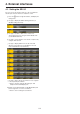
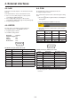
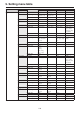
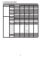
Table Of Contents
- Contents
- Before use
- 1. Basic operations
- 1-1. Background transition
- 1-2. Wipe
- 1-3. Key
- 1-4. PinP (picture in picture)
- 1-5. DSK (downstream key)
- 1-6. Key Link
- 1-7. FTB (Fade to Black)
- 1-8. Internal color signals
- 1-9. Switching the AUX output
- 1-10. Memory
- 1-10-1. Memory registration and recall items
- 1-10-2. Storing the settings in the memory (Store)
- 1-10-3. Recalling the operations stored in the memory (Recall)
- 1-10-4. Memory preview
- 1-10-5. Deleting the operations stored in the memory (Delete)
- 1-10-6. Selecting the buses whose settings are to be registered and or played back
- 1-10-7. Registering the material selection items
- 1-10-8. Setting effect dissolve (shot memory)
- 1-10-9. Editing event memory timelines
- 1-10-10. Registering memories (Register)
- 1-11. Video memories
- 1-12. Memory card
- 1-13. Waveform monitor settings
- 1-14. Setting the status display
- 2. Input/output signal settings
- 2-1. Input signal settings
- 2-1-1. Setting the frame synchronizer
- 2-1-2. Setting the input mode
- 2-1-3. Setting the delay amount
- 2-1-4. Freezing the input signals
- 2-1-5. Setting the material names
- 2-1-6. Setting the up-converter
- 2-1-7. Setting the video process function
- 2-1-8. Setting the analog input gain (option)
- 2-1-9. Setting the analog composite input signals (option)
- 2-1-10. Setting the DVI input signals
- 2-1-11. Displaying the DVI input signal information
- 2-1-12. Adjusting the DVI input signals
- 2-1-13. Automatic adjustment of the black level and white level (analog input signals)
- 2-2. Output signal settings
- 2-3. Setting the sync signals
- 2-4. Adjusting the output signal phase
- 2-5. Setting the multi view display
- 2-6. Setting the ancillary data and embedded audio data
- 2-1. Input signal settings
- 3. System settings
- 4. External interfaces
- 5. Setting menu table
- Appendix (glossary)
- Index
112
4. External interfaces
w Control using the GPI Input port
Assign Item Description of function assigned Control method
AUTO AUTO button in transition area
Operations are performed using
contact inputs (30 ms or more).
CUT CUT button in transition area
KEY ON KEY ON button in transition area
DSK ON DSK ON button in transition area
PinP1 ON PinP1 ON button in transition area
PinP2 ON PinP2 ON button in transition area
FTB FTB button in transition area
BKGD AUTO AUTO button when the background is selected
BKGD CUT CUT button when the background is selected
KEY AUTO AUTO button when the key is selected
KEY CUT CUT button when the key is selected
REC Still1 Still1 recording
REC Still2 Still2 recording
REC Clip1 Clip1 recording start
REC Clip2 Clip2 recording start
STOP Clip1 Clip1 recording stop or playback stop
STOP Clip2 Clip2 recording stop or playback stop
PLAY Clip1 Clip1 playback start
PLAY Clip2 Clip2 playback start
AUX XPT
1 to 24
Crosspoint buttons (1 to 24) used to switch the AUX buses.
Select the AUX buses (AUX1 to AUX4) to be controlled using the
menu.
REDTly DSBL Red tally signal is not output
Functions are enabled using
contact inputs (or disabled in open
status).
GRNTly DSBL Green tally signal is not output
AUXTly DSBL AUX tally signal is not output
No Assign No function assigned
When a plug-in software application is introduced, the functions inherent to that application are sometimes added as the
functions which are assigned.
: This function can be actuated in any model whose system version is V2.00.00 and up.
These operations cannot be performed in a model with a system version of below V2.00.00.