
User Manual
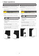
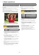
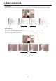
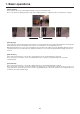
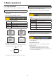
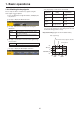
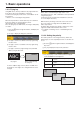
Table Of Contents
- Contents
- Before use
- 1. Basic operations
- 1-1. Background transition
- 1-2. Wipe
- 1-3. Key
- 1-4. PinP (picture in picture)
- 1-5. DSK (downstream key)
- 1-6. Key Link
- 1-7. FTB (Fade to Black)
- 1-8. Internal color signals
- 1-9. Switching the AUX output
- 1-10. Memory
- 1-10-1. Memory registration and recall items
- 1-10-2. Storing the settings in the memory (Store)
- 1-10-3. Recalling the operations stored in the memory (Recall)
- 1-10-4. Memory preview
- 1-10-5. Deleting the operations stored in the memory (Delete)
- 1-10-6. Selecting the buses whose settings are to be registered and or played back
- 1-10-7. Registering the material selection items
- 1-10-8. Setting effect dissolve (shot memory)
- 1-10-9. Editing event memory timelines
- 1-10-10. Registering memories (Register)
- 1-11. Video memories
- 1-12. Memory card
- 1-13. Waveform monitor settings
- 1-14. Setting the status display
- 2. Input/output signal settings
- 2-1. Input signal settings
- 2-1-1. Setting the frame synchronizer
- 2-1-2. Setting the input mode
- 2-1-3. Setting the delay amount
- 2-1-4. Freezing the input signals
- 2-1-5. Setting the material names
- 2-1-6. Setting the up-converter
- 2-1-7. Setting the video process function
- 2-1-8. Setting the analog input gain (option)
- 2-1-9. Setting the analog composite input signals (option)
- 2-1-10. Setting the DVI input signals
- 2-1-11. Displaying the DVI input signal information
- 2-1-12. Adjusting the DVI input signals
- 2-1-13. Automatic adjustment of the black level and white level (analog input signals)
- 2-2. Output signal settings
- 2-3. Setting the sync signals
- 2-4. Adjusting the output signal phase
- 2-5. Setting the multi view display
- 2-6. Setting the ancillary data and embedded audio data
- 2-1. Input signal settings
- 3. System settings
- 4. External interfaces
- 5. Setting menu table
- Appendix (glossary)
- Index
29
1. Basic operations
1-4. PinP (picture in picture)
Another image can be combined with the background image.
This unit supports two PinP channels.
1-4-1. Selecting the PinP channel and
material
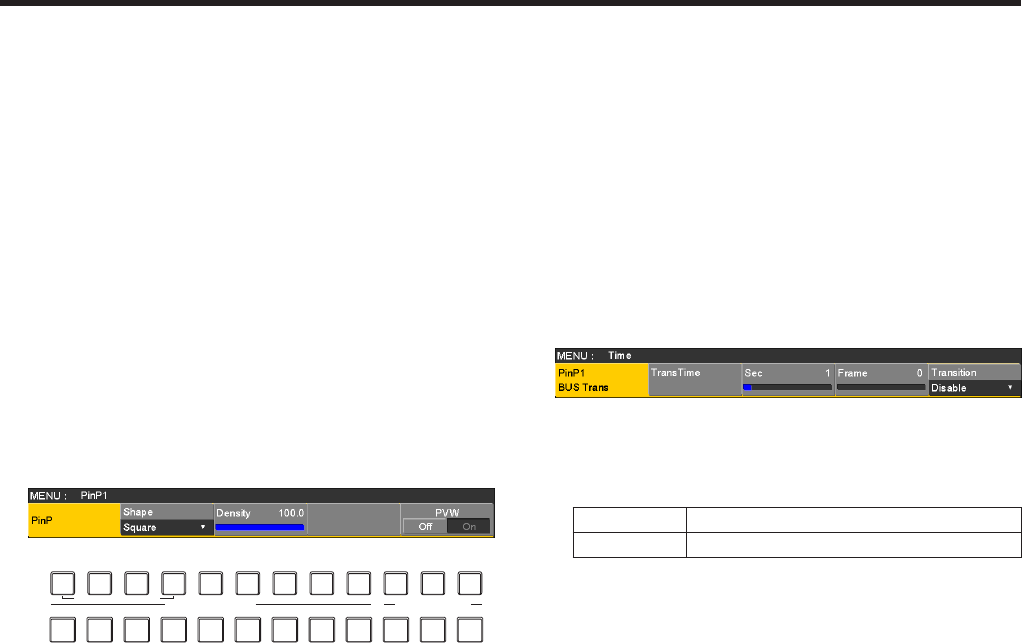
Press the [PinP1] button (or [PinP2] button) among the AUX
bus selector buttons.
When the [PinP1] button (or [PinP2] button) is lit, the PinP1
menu (or PinP2 menu) is displayed on the built-in display.
The state in which the PinP1 materials (or PinP2 materials)
are selected is now established for the AUX bus crosspoint
buttons.
The selected AUX bus crosspoint button lights in amber.
(It will light in red if the selected signal is a PGM output
signal.)
AMBER : FILL / GREEN : SOURCE
KEY PinP1 PinP2 DSK AUX1 AUX2 AUX3 AUX4 DISP MV
AUX BUS DELEGATION
AUX
AUX/DISP SOURCE
SHIFT
PGMPVW
1-4-2. Transition between PinP materials
When a PinP bus material has been selected, the effect to be
produced when images are switched can be executed as a
MIX transition. (Bus transition function)
p When one material set to the Dot by Dot mode and
another material have been switched, cut switching where
the images change in an instant is performed.
1Press the t button to light its indicator, and display the
Time menu.
2Use [F1] to display the PinP1 BUS Trans sub menu (or
PinP2 BUS Trans sub menu).
3Use [F3] and [F4] to set the transition time.
4Use [F5] to set enable or disable for the bus transition
function.
Enable Enable
Disable Disable
While the transition is underway, the indicator of the transition
source button lights, and the indicator of the transition
destination button blinks.
When the transition is completed, the indicator of the
transition source button goes off, and the indicator of the
transition destination button lights.
When another signal has been selected while a transition is
underway, the processing for the transition will continue from
the interim point.