
Operating Instructions

23
1. Parts and their functions
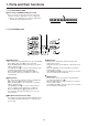
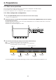
1-1-5. Display area
4
INS
Live Switcher AV-HS410
U1 U2 U3 U4 U5 U6 U7 U8
USER BUTTON
MENU
MODE
PICT
DSK
TIME
PLUGIN
BKGD
CBGD
KEY
CHRKEY
PinP1
PinP2
MENU
HOLD
XPT
MV
IN
OUT
CONFIG
SYS
MENU
OFF
WFM
VECT
VMEM
SD Card
SHOT
EVENT
DISPLAY MENU SELECT
MENU
INPUT
VMEM
BKGD
PATT
KEY
PATT
TAKE
ENTER
� /
+
PAGE
PLAY
REC
STOP
XPT
DSBL
<
CLIP 1
STILL 1
MEMORY / WIPE PATTERN / 10 KEY
<<
TRIM OFF
>>
CLIP 2
STILL 2
REV
TRIM OUT
TRIM IN
9
PASTE
6
MOD
3
REV
C
UNDO
8
COPY
5
DEL
2
>
.
>>
7
NEW
1
<
0/10
<<
STORE
RE
CALL
EDIT
DEL
SHOT
MEM
EVENT
MEM
PLUGIN
MEM1
PLUGIN
MEM2
>
F1 F2 F3 F4 F5
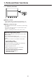
Built-in display
The images, waveforms and menus are displayed by operating the display mode buttons () and menu selection buttons
().
To show images on the built‑in display, press the [DISP] button of the AUX bus selector buttons (6) and light its indicator.
MV, PVW and PGM images can be displayed.
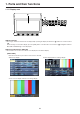
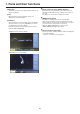
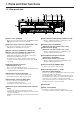
Display mode buttons (DISPLAY)
These buttons are used to select what is to be displayed on the built‑in display.
[MENU MODE]:
Each time this button is pressed, the menu mode is switched.
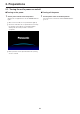
Menu‑only display
1 line of menu display and full‑screen image display
Menu display/Subscreen/Image display