
Datasheet


AV1 (GW) Interlock Switches
–5–
AECTB20E 201701-T
3 Form A type
CAUTIONS FOR USE
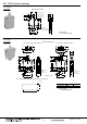
External dimensions
3 Form A type without button guard
7.6
10.6
13.8
14.8
6.35
8
18
51
2.1
47.8
50
7.6 0.8
0.8
0.8
33.3
(FP)
(OP)
(TTP)
8 dia.
30.4
±0.8
45.6
±0.8
15.2
±0.8
.250
Quick-
connect
terminal
3 Form A type with button guard
7.6
10.6
13.8
14.8
6.35
8
18
51
2.1
47.8
50
7.6 0.8
0.8
0.8
33.3
(FP) (TTP)
(OP)
30.4
±0.8
45.6
±0.8
15.2
±0.8
.250
Quick-
connect
terminal
14
6
20.9
18
8 dia.
Recommended panel opening dimensions (common)
15
A
R1.3 max.
Panel thickness 1.0 2.5
Dimension A 47.0 47.3
Contact gap
3 Form A: Min. 8mm
CAD Data
Tolerance: ±0.1
■ Switch mounting
(Screw mounting type)
1) Mount the switch to a smooth surface
using M4 screws. Tighten the screws with
0.3 to 0.5 N·m torque. To prevent
loosening of the mounting screws, it is
recommended that spring washers be
used in combination with adhesive
material for locking the screws.
(One-touch mounting type)
Mount on cut panel shapes with
dimensions shown in the drawing.
If you are considering panels that fall
outside recommended shapes and
dimensions, please contact us.
2) With respect to the position of the
operating device and the switch body, set
the position as indicated in the condition.
If this condition is exceeded, the
mechanical and electrical performance
will be impaired. In addition, the force
applied by the operating device should be
in a perpendicular direction. Even if the
pushbutton is used in the full total travel
position (OT), there will be no influence
on the life of the switch.
(Screw mounting type)
(Snap-in mounting type)
■ Connection method
With respect to the terminal connections,
it is recommended that receptacles with
insulating sleeves, easy lock connectors
or positive lock connectors be used.
Also, consideration should be given to the
wiring not to apply force to the terminal
section normally.
■ Operation speed
In perpendicular operation, avoid using
operating speeds beyond range of 10 to
300 mm/sec.
■ Environment
Avoid using and storing these switches in
a location where they will be exposed to
corrosive gases, silicon, or high dust
levels, all of which can have an adverse
effect on the contacts.
AV1
switch
AV1
switch
Free condition Operation condition
More than
17 mm
10 to
10.5 mm
Operating
device
Operating
device
Operating
device
Free condition Operation condition
More than
14.5 mm
7.5 to 8 mm