
Datasheet


Technical Terminology & Cautions for Use
–3–
AECTB36E 201701-T
TECHNICAL NOTES ON ELECTRICAL CHARACTERISTICS
CAUTIONS IN A CIRCUIT
1) The snap-action switch is designed for AC operations. While it
has small contact gaps and no arc absorber, it may be used for
low-capacity DC operations.
Please refer to the rating of each products
2) For applications with very small switching voltage or current,
choose the low-level load type (Au contact).
3) When selecting a contact type of a snap-action switch to be
used for low-level load switching, the following should be noted.
Silver contacts’ surfaces are prone to be oxidized and form a
sulfide film. The switch operates with no problems at the
beginning of use. However, as the contact surfaces develop films
with time, the film may not be broken by the switching operation,
causing a conduction failure. Therefore, please choose the Au
contact type for switching a load of 0.1 A or below.
4) Application to Electronic Circuits
• The snap-action switch contacts can sustain bounce or chatter
when closed. Bounce or chatter can cause noise or pulse count
errors when the snap action switch is used in electronic circuits.
• If contact bounce or chatter poses problems in the vicinity of
the OP and RP, use a suitable absorption network, such as a C/
R network.
5) Check the surge current, normal current and surge duration.
6) Contact resistance given in performance specifications is
measured with a voltage drop method using 6 to 8 V DC, 1 A
(except for low-level load type). Contact resistance across COM
and NC terminals is measured in the free position, while contact
resistance across COM and NO terminals is measured in the
total travel position.
7) To prevent contact welding failure, be sure to use a serial
resistance for each capacitive load.
8) If snap-action switch operation is synchronized with the AC
supply phase, this may cause: shortened electrical life, contact
fusion failure, contact transfer, or other reliability problems.
Small current and voltage application range (Au contact)
500
100
50
5
2
1
4 8 12 16 20 24
10
DC voltage (VDC)
Current (mA)
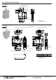
1) Contact protection is recommended when snap-action
switches are used in an inductive load circuit.
2) Do not connect the
contacts on individual
switches to different
type or different poles of
the power supply.
Examples of power
supply connections
(connection to different
poles)
Example of wrong
power supply
connection (connection
to different poles of
power supply)
This may lead to mixed
DC and AC.
3) Avoid circuits which
apply voltage between
contacts. (This may lead
to mixed deposition.)
Circuit diagram Cautions for use
Contact for snap-action switch
(1) r = more than 10 Ω
(2) In an AC circuit
Impedance of R is to be slightly smaller
than impedance of r and c.
Contact for snap-action switch
Can be used for both AC and DC.
Impedance of r is nearly equal to
impedance of R.
C: 0.1 μF
Contact for snap-action switch
(1) For DC circuits only.
Contact for snap-action switch
Can be used for both AC and DC.
rc
R
r
c
R
R
diode
ZNR
Varistor
Induction load
PL
Wrong
Solenoid load
Lamp load
PL
Right
Solenoid load
Lamp load
Load connected to same pole
L
Load
L
Load
AC
DC
Wrong
Wrong
L
100V
200V