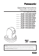
Operating Instructions HD Integrated Camera Model No. Model No. Model No. Model No. Model No. Model No. Model No. Model No. AW‑HE40HWP AW‑HE40HKP AW‑HE40HWE AW‑HE40HKE AW‑HE40SWP AW‑HE40SKP AW‑HE40SWE AW‑HE40SKE ● How the Operating Instructions are configured : The describes the procedure for basic operation and installation. Before installing this unit, be sure to take the time to read through to ensure that the unit will be installed correctly.
Trademarks and registered trademarks ●● Microsoft®, Windows®, Windows® 7, Windows® 8, Windows® 8.1, Internet Explorer® and ActiveX® are either registered trademarks or trademarks of Microsoft Corporation in the United States and other countries. ●● Intel® and Intel® CoreTM are trademarks or registered trademarks of Intel Corporation in the United States and other countries.
Contents Before use 4 46 Others 1/4 screen Overview Others 2/4 screen 4 47 Required personal computer environment Others 3/4 screen 4 48 Disclaimer of warranty Others 4/4 screen 5 49 Network security Maintenance screen 5 50 Firmware Version screen 50 Basic shooting operations 6 IP Network screen 51 How to turn the power on and off 7 Camera menu item table 52 Turning the power on 7 Turning the power off Displaying the web screen 7 55 Displaying th
Before use ■■Overview ●● The unit is a compact full HD camera integrated with a pan-tilt head and featuring a 1/2.3-type MOS sensor and digital signal processor (DSP). ■■Required personal computer environment CPU When using 1080/60p [59.94Hz] and 1080/50p [50Hz] Intel® CoreTM i7 3.4 GHz or higher recommended Other than above Intel® CoreTM2 Duo 2.4 GHz or higher recommended Memory For Windows: 1 GB or higher (2 GB or higher for Microsoft® Windows® 8.
Before use (continued) IMPORTANT ●● Failure to provide the required personal computer environment may slow down the delineation of the images on the screen, make it impossible for the web browser to work and cause other kinds of problems. ■■Network security As you will use the unit connected to a network, your attention is called to the following security risks.
Basic shooting operations 1 2 3 Set the subject brightness to the appropriate level. Turn on the power of all the units and devices in the system. Select the unit to be operated. Even when using only one unit, it must still be selected from the wireless remote control or controller. 4 Select the shooting mode. Select one of the four (Full Auto, Manual1, Manual2 and Manual3) preset shooting modes (scene files), each of which corresponds to a set of circumstances in which the subject will be shot.
How to turn the power on and off ■■Turning the power on ■■Turning the power off When performing the operations using the wireless remote control When performing the operations using the wireless remote control 1 Set all the power switches of the units and devices connected in the system to ON. ●● The unit does not have a power switch. When power is supplied to it, the status display lamp will light up orange. 2 3 1 2 The POWER ON mode is established, images are output, and control can be exercised.
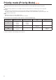
Priority mode (Priority Mode) Changing the priority mode enables the unit to perform operation for various applications. (page 44, page 65) IP: Enables IP image transmission over multiple channels. The IP transmission of H.264 images is also supported. SD card: Inserting an SD card (optional accessory) into the unit enables recording H.264 images to the SD card. The data recorded to the SD card can be played back on the Web screen, downloaded to a personal computer, and transferred to an FTP server.
Selecting the units When performing the operations using the wireless remote control 1 When performing the operations using the controller When using an AW-RP50, AW-RP120 or AK-HRP200: Press the [CAM1], [CAM2], [CAM3] or [CAM4] button. Refer to the Operating Instructions of the controller. The unit’s status display lamp blinks green when a signal matched by the remote control ID has been received, and it blinks orange when a signal that is not matched by the remote control ID has been received.
Selecting the shooting modes (scene files) ■■How to select the shooting mode 4 (continued) Press the [○] button. The “Camera” sub‑menu is displayed on the monitor. ** Camera ** When performing the operations using the wireless remote control Scene Contrast Level Day/Night Night-Day Level 2, 8 1 Full Auto 0 Day ---- Return 3, 5, 7 5 4, 6, 7 6 1 2 Press the [CAM1], [CAM2], [CAM3] or [CAM4] button to select the unit. 7 The Top Menu is displayed.
Shooting When performing the operations using the wireless remote control ●●Changing the camera’s direction Moving the camera toward the left or right (panning): Press the [◄] or [►] button. Moving the camera up or down (tilting): Press the [▲] or [▼] button. Moving the camera diagonally: Press the [▲] or [▼] button and [◄] or [►] button at the same time. Returning the camera to the reference position: Press the [HOME] button for 2 seconds.
What to do when encountering problems in the basic shooting operations If the trouble is not resolved by taking the action suggested below, refer to “Troubleshooting” (page 124). When performing the operations using the wireless remote control The unit does not move. ●● Press the [CAM1], [CAM2], [CAM3] or [CAM4] button to select the unit which is to be operated. If only one unit is being used, it is normally selected using the [CAM1] button. ●● Check that the IR ID has been set correctly.
More advanced operations Manual shooting (pages 14 to 15) ●● ●● ●● ●● Manual adjustment of focus Manual adjustment of iris Manual adjustment of shutter speed Manual adjustment of gain Black level (master pedestal) adjustment (page 21) ●● This adjustment is performed to align the black level (pedestal level) of a multiple number of cameras.
Manual shooting ■■Manually adjusting the focus The lens focus can be adjusted manually. ■■Manually adjusting the iris The lens iris can be adjusted manually. When performing the operations using the wireless remote control When performing the operations using the wireless remote control 1 Press the [M/FOCUS] button to switch the focus to manual adjustment. 2 Press the [F] or [N] button of [FOCUS] to adjust the focus.
Manual shooting (continued) ■■Manually adjusting the shutter speed The shutter speed can be set using two methods. One is a method that specifies the time (where a time such as 1/250 sec. is designated), and the other is a method that specifies the frequency (where synchro scan, 60.15 Hz, etc. is designated). When shooting a TV screen or PC monitor screen, the horizontal noise generated when the screen is shot can be minimized by adjusting the frequency to the screen frequency using synchro scan.
Preset memories The unit enables up to 100 settings for the camera direction (panning and tilting), zoom, focus, iris, gain and white balance to be registered in its preset memories, and called. However, the number of settings that can be registered and called depends on the type of wireless remote control or controller that is used for operation. ●● The focus and iris operating modes (manual and auto settings) are not registered. The current focus and iris values are registered.
White balance adjustment ■■White balance adjustment ●●Automatic adjustment (AWB: AWB A or AWB B) In order for the white to be reproduced accurately, the ratio between the three primary colors (RGB) is adjusted. If the white balance has shifted out of adjustment, not only will the white be reproduced poorly but the color tones of the entire screen will also be degraded. ●● This adjustment must be performed when using the unit for the first time or when the unit has not been used for a prolonged period.
White balance adjustment 5 (continued) Press the [▲] or [▼] button to bring the cursor to “White Balance Mode”. When performing the operations using the controller When using an AW-RP50, AW-RP120 or AK-HRP200: 6 Press the [○] button. “White Balance Mode” starts blinking. 7 8 Press the [▲] or [▼] button to change the White Balance Mode to be used to “AWB A” or “AWB B”, and press the [○] button to enter the selection. Press the [MENU] button for 2 seconds. The camera menu display is exited.
White balance adjustment (continued) ●●Auto tracking white adjustment (ATW) ●●3200K and 5600K presets When white balance adjustment is set to “ATW”, the white balance will be corrected automatically, even if the light source or color temperature changes. When “3200K” or “5600K” is selected for the white balance, the white balance is set using a color temperature of 3200K (equivalent to halogen light) or 5600K (equivalent to daylight), respectively.
White balance adjustment (continued) ●●Manual adjustment (R gain and B gain adjustment) 5 Press the [○] button. “White Balance Mode” starts blinking. White balance can be adjusted manually. 6 Note ●● R/B gain adjustments can only be performed when White Balance Mode is set to “AWB A”, “AWB B” or “VAR”. When performing the operations using the wireless remote control ●● Steps 1 through 6 represent the procedure for selecting the “AWB A”, “AWB B” or “VAR” memory.
Black level (master pedestal) adjustment ■■Black level (master pedestal) adjustment 6 The black level can be adjusted when using a multiple number of cameras including the unit. Ask your dealer to perform this adjustment. (Use an oscilloscope or waveform monitor for the adjustment.) Adjust the black level in accordance with the units and devices used.
Basic operations Camera menus are displayed on the monitor when the unit’s settings are to be selected. The monitor is connected to the video signal output connector. The basic camera menu operations involve displaying sub‑menus from the Top Menu items, and selecting settings on the sub‑menus. Some sub‑menus have menu items for performing more detailed settings. Only the steps taken using the wireless remote control will be described here for the operations conducted to select and set the items.
Basic operations Camera menu operation (continued) Wireless remote control Exiting the camera menu Press the [MENU] button for operations 2 seconds. Controller AW‑RP50 AW-RP120 AK-HRP200 Press the [CAMERA OSD] button for Press and hold the [CHARA/MENU] 2 seconds. button for about 2 seconds. Notes ●● Perform the menu operations and exit from the menus using the controller which displayed the Top Menu.
Basic operations (continued) ■■When performing the 8 1 9 operations using the wireless remote control 2 Press the [CAM1], [CAM2], [CAM3] or [CAM4] button to select the unit which is to be operated. Press the [MENU] button for 2 seconds. The Top Menu is displayed. 3 Press the [▲] or [▼] button to bring the cursor to the item to be selected. Each time the [▲] or [▼] button is pressed, the cursor moves. The cursor can be moved in the same way using the [◄] and [►] buttons. 4 Press the [○] button.
Basic operations (continued) ■■Operations on the AW‑RP50 Remote Camera Controller F1 F2 POWER ALARM MENU PAGE STORE DELETE IRIS AUTO 1 2 3 4 5 GAIN/PED R/B GAIN R/B PED AWB/ABB SHUTTER 6 7 8 9 10 DETAIL 1 SETUP SCENE/MODE CAMERA PRESET MEMORY / MENU 2 3 SYSTEM 4 F1 CAMERA OSD F2 EXIT USER1 USER2 5 PT ACTIVE CAMERA STATUS / SELECTION AUTO For operating the camera menus.
Basic operations (continued) ●●Color temperature setting (COLOR ●●Preset speed table setting (PRESET 1 1 TEMP) Press the [MENU] button on the AW-RP50. SPEED) The [MENU] button lights, and the [PRESET MEMORY/ MENU] buttons become selectable. 2 Press the [4 (AWB/ABB)] button in the [PRESET MEMORY/MENU] area. The [MENU] button lights, and the [PRESET MEMORY/ MENU] buttons become selectable. 2 The button lights, and the AWB/ABB menu appears on the LCD panel. 3 Turn the F1 dial to select “VAR”.
Basic operations (continued) ●●Freezing images during preset playback ●●Digital image stabilization function 1 1 (FREEZE DURING) Press the [MENU] button on the AW-RP50. setting The [MENU] button lights, and the [PRESET MEMORY/ MENU] buttons become selectable. 2 Press the [9 (SETUP)] button in the [PRESET MEMORY/MENU] area. The [MENU] button lights, and the [PRESET MEMORY/ MENU] buttons become selectable. 2 The button lights, and the SETUP menu appears on the LCD panel.
Basic operations (continued) ●●Digital extender (D.EXTENDER) function setting 1 Press the [MENU] button on the AW-RP50. The [MENU] button lights, and the [PRESET MEMORY/ MENU] buttons become selectable. 2 Press the [9 (SETUP)] button in the [PRESET MEMORY/MENU] area.
Basic operations (continued) ■■Operations on the AW‑RP120 Remote Camera Controller For operating the camera menus. CAMERA OSD: When this is pressed for 2 seconds, the selected camera menu is displayed, overlapping the camera output image. When it is pressed for 2 seconds while a camera menu is displayed, the menu is exited. F1: Turn F1 to move the cursor up and down in the camera menu or to change setting values.
Basic operations (continued) ●●Color temperature setting (COLOR ●●Freezing images during preset playback 1 1 TEMP) Press the [EXIT] button and the [ATW] button of [WHITE BAL] simultaneously. The [A], [B], and [ATW] buttons of [WHITE BAL] light, and color temperature setting mode is enabled. The color temperature setting value appears on the LCD screen during this time. 2 Turn the F1 dial to change the color temperature.
Basic operations (continued) ●●Digital extender (D.EXTENDER) function setting 1 Press the [MENU] button on the AW-RP120. The [MENU] button lights. 2 Press the FUNCTION menu [23] button. The button lights, and the OPTION menu appears on the LCD panel. 3 Turn the F1 dial to select “D. EXTENDER”, then press the F1 dial.
Basic operations (continued) ■■Operations on the AK‑HRP200 Remote Operation Panel HEAD POWER AUTO VF POWER BARS TEST 5600K MATRIX SKINDTL WHITE BLACK KNEE OFF DTL OFF SET UP SHUTTER ON STEP/SYNC SCENE/USER FILE SHIFT SCENE 1 SCENE 2 SCENE 3 USER 1 USER 2 USER 3 SCENE 4 STORE GAIN VR LOCK DTL UP FLARE/PED CC ND SHT M.GAIN CAMERA SYNC M.PED 10-19 DATA SET For operating the camera menus.
Basic operations (continued) The following operations can be performed from the AK-HRP200 Remote Operation Panel. For details on operations, refer to the AK-HRP200 Operating Instructions . Control/display component Label AW-HE40 : Supported : Supported with some restrictions —: Not supported HEAD POWER Remarks 1 Camera power switch 2 Viewfinder power switch VF POWER — 3 Color bar signal output switch BARS/TEST Does not transition to TEST_ON.
Basic operations (continued) Control/display component Label AW-HE40 : Supported : Supported with some restrictions —: Not supported Remarks SHT The shutter value is fixed during transition from SYNC. • For 59.94p, 59.94i: 1/100 • For 29.97p: 1/100 • For 50p, 50i: 1/120 • For 25p: 1/120 SYNC The display for 7SEG will be “----” during SYNC. CAM No.
Camera menu items ■■Setting the camera menu items ■■Top Menu screen When the unit’s settings are to be selected, the camera menus are displayed on the monitor. The monitor is connected to the video signal output connector. The basic camera menu operations involve displaying sub‑menus from the Top Menu items, and selecting settings on the sub‑menus. Some sub‑menus have menu items for performing more detailed settings.
Camera menu items (continued) ■■Camera screen (when Full Auto is selected) ■■Camera screen (when Manual1 to 3 is selected) This menu is used for the camera image settings. ** Camera ** ** Camera ** Scene Contrast Level Day/Night Night-Day Level Scene Contrast Picture Matrix Full Auto 0 Day ---- Manual1 Return Return Scene [Full Auto, Manual1, Manual2, Manual3] Selected here is the shooting mode that matches the shooting situation.
Camera menu items (continued) ■■Contrast 1/2 screen *** Contrast 1/2 *** Contrast Mode Auto Contrast Level 0 Shutter Mode ---Step/Synchro ---Frame Mix ---Auto F.Mix Max Gain 0dB Gain Auto AGC Max Gain 24dB Return Frame Mix [Auto, Off, 6dB, 12dB, 18dB, 24dB] Select for frame addition (gain-up using sensor storage) amount. This item can be set when “Off” is selected as the “Shutter Mode” item setting. When frame addition is performed, it will appear as if the images are missing some frames. Auto F.
Camera menu items (continued) ■■Contrast 2/2 screen *** Night-Day Level [Low, Mid, High] Contrast 2/2 *** Day/Night Night-Day Level Day ---- Adjust the level used while switching from Night mode to Day mode when Day/Night is set to “Auto”. ● This can only be configured when Day/Night is set to “Auto”. Return Use this to return to the previous menu. Return Day/Night [Day, Night, Auto] This is used to select normal shooting or low light shooting (by exposing the subjects to infrared rays).
Camera menu items (continued) ■■Picture 1/3 screen R Gain, B Gain [–30 to +30] *** Picture 1/3 *** Chroma Level White Balance Mode Color Temperature R Gain B Gain Pedestal 0 AWB A ---0 0 0 Return Chroma Level [–3 to +3] Set here is the color intensity (chroma level) of the images. When “AWB A”, “AWB B” or “VAR” is selected as the White Balance Mode setting, the white balance can be finely adjusted after automatic white balance (AWB) has been performed.
Camera menu items (continued) ■■Picture 2/3 screen Notes *** Picture 2/3 *** Detail Detail Level H Detail Level L Flesh Tone Mode HDR DRS Gamma Type Gamma Level Low 18 9 Off Off Off Normal Mid Return Detail [Off, Low, High] The image detail (image sharpness) is adjusted here. When “Low” or “High” is selected, the detail is enhanced. Detail Level H [Detail Level L setting +1 to 18] The image sharpness level is adjusted here when “High” has been selected as the “Detail” setting.
Camera menu items (continued) ■■Picture 3/3 screen *** Picture 3/3 *** Back Light COMP. DNR Off Low Return Back Light COMP. [Off, On] “On” or “Off” is set here for the backlight compensation function. Under backlight conditions, the function prevents darkening as a result of light striking the backs of subjects, and makes it possible to shoot images in shade or shadow more brightly. The function takes effect when “Auto” has been selected as the Contrast Mode, Gain or Frame Mix item setting.
Camera menu items (continued) ■■16-axis color matrix (These operations can be performed only when Manual1 to 3 has been selected as the Scene setting.) Matrix Type [Normal, EBU, NTSC, User] The preset color matrix data is loaded, and the saturation and phase are compensated accordingly. When “User” is selected, the saturation and phase can be finely adjusted using the 16-axis color matrix (B to Cy_B_B).
Camera menu items (continued) ■■System screen This is the menu in which the camera’s output image settings are configured. ## System ## Output Others Return Output This displays the Output screen on which to select the camera’s output image settings. Others This displays the Others screen on which to select the settings for the installation status of the camera’s pan-tilt head unit and operating speed as well as the settings relating to the other functions.
Camera menu items (continued) ■■Output screen Priority Mode [IP, SD card, USB] ### Output ### Format Frequency Priority Mode 1080/59.94i 59.94Hz IP Return Format For 59.94Hz: [Auto, 1080/59.94p, 1080/59.94i, 1080/29.97PsF, 1080/29.97p, 720/59.94p] For 50Hz: [Auto, 1080/50p, 1080/50i, 1080/25PsF, 1080/25p, 720/50p] The video format is changed on this screen. The formats of the images which can be output differ between the AW-HE40H and AW-HE40S.
Camera menu items (continued) ●●Changing the format ●●Changing the frequency When the format is changed on the Output screen from its current setting, the pre-format-change confirmation screen appears. When the currently selected frequency is changed in the Output screen, the frequency-change confirmation screen appears. Note Pre-format-change confirmation screen ●● When using a monitor that does not support the 59.94 Hz or 50 Hz frequencies, images may not be output after the frequency is changed.
Camera menu items (continued) ■■Others 1/4 screen ### Others 1/4 ### Install Position Desktop Preset Speed Table Fast Preset Speed 10 Preset Scope Mode A Freeze During Preset Off Speed With Zoom POS. On Focus Mode Auto Focus ADJ With PTZ. ---Return Install Position [Desktop, Hanging] “Desktop” or “Hanging” is selected here as the method used to install the unit.
Camera menu items (continued) ■■Others 2/4 screen Tally [Disable, Enable] “Enable” or “Disable” is set here for the function which turns on or turns off the tally lamp using the tally control signal. ### Others 2/4 ### Zoom Mode Max Digital Zoom Image Stabilizer Tally IR Control IR ID D.Zoom ×16 Off Enable Enable CAM1 Return Zoom Mode [Opt.Zoom, i.Zoom, D.Zoom, D.Extender] Configure the maximum zoom magnification. Opt.Zoom: Use only the optical zoom. Up to 30x optical zoom is possible. i.
Camera menu items (continued) ■■Others 3/4 screen ### Others 3/4 ### CAM/BAR Bars Type OSD Off With Tally OSD Status Camera Type2 Off Off Return CAM/BAR [Camera, Colorbar] Switch between color bar display and camera image display on the monitor and the web setup screen. Note ●● When the color bar is displayed, a test tone (1 kHz) is output according to the Audio setting in the camera menu. Bars Type [Type1, Type2] Change the type of color bar to display.
Camera menu items (continued) ■■Others 4/4 screen Protocol Model Select [SEVIHD1, SBRC300, SBRCZ330, Reserved1 to 7] ### Others 4/4 ### Audio Input Volume Plugin Power ALC Equalizer Protocol Model Select Off ------On Off Set the protocol model for standard serial communication. Do not select “Reserved1” to “Reserved7”. Return Use this to return to the previous menu. SEVIHD1 Return Audio [Off, On] Enable/disable the audio input signal from the device connected to the audio input connector.
Camera menu items (continued) ■■Maintenance screen ■■Firmware Version screen ### Firmware Version ### ## Maintenance ## Firmware Version IP Network Initialize Ver.1.0 Return Return Firmware Version This is selected to display the Firmware Version screen on which to check the version of the firmware used. This displays the unit’s firmware version. Return Use this to return to the previous menu.
Camera menu items (continued) ■■IP Network screen ●●Concerning initialization ### IP Network ### When “Initialize” is selected on the Maintenance screen, the Initialize screen appears. IP Address Initialize screen 192. 168. 0. 10 Subnet Mask 255. 255. 255. 0 Default Gateway 192. 168. 0. 1 Return IP Address This is selected to display the IP address which has been set for the unit. Subnet Mask This is selected to display the subnet mask which has been set for the unit.
Camera menu item table Camera menu Top Menu Camera Item Scene Contrast Contrast 1/2 Scene Full Auto Contrast Mode Contrast Level Shutter Mode Step/Synchro (When “Step” is selected as the “Shutter Mode”) ---0 ------- 52 Manual1 to Manual3 Auto 0 Off [59.
Camera menu item table Camera menu Top Menu Camera Scene Matrix Item Matrix 2/3 Matrix 3/3 System (continued) Output Matrix Type R_R_Yl Saturation Phase R_Yl_Yl Saturation Phase Yl Saturation Phase Yl_Yl_G Saturation Phase Yl_G_G Saturation Phase G Saturation Phase Matrix Type G_Cy Saturation Phase Cy Saturation Phase Cy_Cy_B Saturation Phase Cy_B_B Saturation Phase Format Frequency Others Others 1/4 Others 2/4 Others 3/4 Factory setting Full Auto ------------------------------------------------
Camera menu item table Camera menu Top Menu System Others Others 4/4 Maintenance Firmware Version IP Network Initialize 54 (continued) Item Factory setting Full Auto Manual1 to 3 Audio Input Volume Off Line Middle Plugin Power ALC Equalizer Off On Off Protocol Model Select SEVIHD1 ---IP Address Subnet Mask Default Gateway ---- Version shipped 192.168.0.10 255.255.255.0 192.168.0.
Displaying the web screen With a personal computer connected to the unit, it is possible to view the camera’s IP videos or select various settings from the web browser. Select an IP address for the personal computer within the private address range while ensuring that it is different from the address of the unit. Set the subnet mask to the same address as the unit. Unit’s IP address and subnet mask (factory settings) IP address: 192.168.0.10 Subnet mask: 255.255.255.0 Range of private addresses: 192.168.0.
Displaying the web screen (continued) Note ●● If the personal computer does not have the plug‑in viewer software already installed, an installation confirmation message is displayed before the live screen [Live] is displayed. In a case like this, follow the on-screen instructions to install the software. Switching between the Live screen [Live] and Web setup screen [Setup] When the live screen [Live] is displayed, click the button.
Web screen operations The live screen [Live] includes a “single display mode” that displays IP images from a single camera and a “multi display mode” that displays IP images from multiple cameras. See below for details on the single display mode, and see page 62 for details on the multi display mode. Live screen [Live] : Single display mode You can display images from the camera on a personal computer and perform camera operations, such as pan, tilt, zoom, and focus control.
Web screen operations (continued) 1. Menu switching [Other Menu >>] / [Stream Menu >>] Switch between menu displays. Clicking [Other Menu >>] when the Stream menu is displayed displays the Other menu. Clicking [Stream Menu >>] when the Other menu is displayed displays the Stream menu. ●● The Stream menu is always displayed when the web screen is updated and the Live screen is displayed from another screen. However, this is not the case when recording to an SD card. 2.
Web screen operations (continued) 5. SD Card Operation buttons [SD Card Operation] Perform the operations for recording the video and audio captured with the unit to an SD card. [Rec] Starts recording to an SD card. The SD access lamp on the top right of the screen is displayed in red during recording. Stops recording to an SD card. [Stop] Displays a list of the recorded content. [Play List] 6.
Web screen operations (continued) 9. Main area (IP video display area) 12.Control pad and its buttons To adjust the image in the horizontal or vertical direction (panning or tilting), leftclick the pad and the buttons. The more the outside of the pad is clicked, the faster the camera operates. Adjustment is also possible by dragging the mouse. Right-click the pad to initiate zooming and focusing.
Web screen operations (continued) 15.Preset [Preset] [Home] [Move] When the Web screen is open, this is blank. When the preset position is selected from the pull‑down menu and the [Move] button is clicked, the camera direction moves to the preset position which was registered ahead of time. Preset positions are registered on the preset position screen. The camera direction moves to the preset position which is now selected on the pull‑down menu.
Web screen operations (continued) Live screen [Live] : Multi display mode In this mode, the images of a multiple number of cameras can be monitored on one screen (called the ‘multi screen’). The image of 4 cameras or max. 16 cameras can be monitored at one time. When the camera title of any of the images is clicked, the live screen [Live] (single display mode) of the camera concerned is displayed as a separate window.
Web screen configurations Logging into the Web setup screen [Setup] 1. Turn on the power of the unit from the standby mode state. 4. Click the [OK] button. Click [OK] again when the following screen appears. 2. Click the [Setup] button. (page 56) The login screen appears. Notes 3. Enter the user name and password. The factory settings for the user name and password are as follows.
Web screen configurations (continued) Web setup screen [Setup] The settings for the unit are selected on this screen. Note ●● The setting menu operations can be performed only by users whose access level is “1. Administrator”. For the procedure used to set the access level, refer to page 87. 9 8 1 2 3 4 5 6 7 1. Basic button [Basic] When the Basic button is pressed, the Basic screen is displayed in the main area. “Basic screen [Basic]” (page 65) 6.
Web screen configurations (continued) Basic screen [Basic] Priority mode tab [Priority Mode] Set the priority output of video. Clock settings tab [Date&Time] Configure the settings for the clock. Set the clock using any of the three methods: “PC synchronization”, “NTP”, and “Manual”. Priority Mode Configure the setting for the priority output of video. Setting value: IP Enables IP image transmission over multiple channels. The IP transmission of H.264 images is also supported.
Web screen configurations (continued) Manual - Summer time (daylight saving) Sets whether to use summer time. Selects the time zone that corresponds with the region in which the unit is going to be used. Setting value: In Sets the time to summer time. Out Cancels summer time. Auto Switches to summer time according to the start/end time and date settings (time, day, week, month). Live page tab [Live page] Configure the setting for the camera title.
Web screen configurations (continued) SD card tab [SD memory card] Configure the format settings for the video to be recorded to an SD card or initialize a card. ●● The priority mode needs to be set to “SD card”. For details, refer to “Priority mode tab [Priority Mode]” (page 65). Record tally Turn the function for the tally lamp to light when recording to an SD card on/off.
Web screen configurations (continued) Image screen [Image/Audio] IP video settings tab [Video over IP] The JPEG image and H.264 image settings as well as the settings related to image quality are selected on this screen. zz Initial display settings for “Live” page Stream Select the images to display when the Live screen [Live] is opened. Setting value: H.264(1) Display videos (H.264(1)). H.264(2) Display videos (H.264(2)). H.264(3) Display videos (H.264(3)). H.264(4) Display videos (H.264(4)).
Web screen configurations (continued) There are restrictions on the simultaneous transmission of JPEG and H.264. For details, refer to page 72. zz JPEG(1) • JPEG(2) • JPEG(3) Configure the settings for JPEG images. JPEG transmission Set whether to transmit JPEG images. Factory settings: On Image capture size Select from the following resolutions for the images to be displayed when displaying JPEG images.
Web screen configurations (continued) Image capture size Select the resolution for H.264 images. Selectable options will vary depending on the selected resolution setting. Setting value: H.264(1) 1920×1080 1280×720 640×360 (when HDR is “Low” or “High”) H.264(2) 1280×720 640×360 320×180 H.264(3) 1280×720 640×360 320×180 H.264(4) 1280×720 640×360 320×180 Factory settings: H.264(1): 1920×1080 H.264(2): 1280×720 H.264(3): 640×360 H.
Web screen configurations (continued) Transmission type Select the transmission format for H.264 images. Setting value: Unicast port (AUTO) Up to 14 users can access a single camera at the same time. [Unicast port (Image)] and [Unicast port (Audio)] will be configured automatically when images and audio are sent from the camera. We recommend selecting the [Unicast port (MANUAL)] setting when the port number transmitting the H.264 images does not need to be fixed (e.g., during use within a network).
Web screen configurations (continued) List of settings for transmission output of IP video Settings H.264(1) Resolution H.264(2)*1 H.264(3)*1 H.264(4)*2 1280×720*1 1280×720 1280×720 1280×720 1280×720*1 640×360*3 640×360 640×360 640×360 640×360 320×180 320×180 320×180 320×180*1 30fps 30fps 30fps 30fps 30fps 15fps 15fps 15fps 15fps 15fps 5fps 5fps 5fps 5fps 5fps 25fps 25fps 25fps 25fps 25fps 12.5fps 12.5fps 12.5fps 12.5fps 12.
Web screen configurations (continued) Audio [Audio] Configure audio settings. Notes ●● Images and audio are not synchronized. Therefore, images and audio may be slightly out of sync. ●● The audio may skip depending on the network environment. Plugin Power Turn plug-in power off/on. Factory settings: Off ALC Turn automatic level adjustment for the audio off/on. Factory settings: On Equalizer Set the equalizer function. Setting value: Off Do not use the equalizer function.
Web screen configurations (continued) Image adjust / preset position screen [Image/Position] zz Contrast [Contrast] Display the image quality adjustment / preset position screen. Image adjust When you click the [Setup] button, the image adjust screen [Image adjust] appears. Preset position When you click the [Setup] button, the preset position screen [Preset position] appears. (page 80) zz Image adjust screen [Image adjust] Adjust the image quality.
Web screen configurations (continued) Shutter Mode zz Gain Select for camera shutter mode. This item can be set when “Manual” has been selected as the “Contrast Mode” setting. When a higher shutter speed is selected, fast-moving subjects do not become blurred easily but the images will be darker. Setting value: Off The shutter is set to OFF (so that it cannot be tripped). Step The step shutter is set (the steps can be changed).
Web screen configurations (continued) zz Picture White Balance Mode The white balance mode is selected here. Select the mode when the coloring is not natural because of the nature of the light source or other factors. If the white color serving as the reference can be recognized, subjects can be shot with natural coloring. Setting value: ATW This mode automatically corrects the white balance, even if the light source or color temperature changes.
Web screen configurations (continued) Detail The image detail (image sharpness) is adjusted here. When “Low” or “High” is selected, the detail is enhanced. Setting value: Off, Low, High Factory settings: Low Detail Level H The image sharpness level is adjusted here when “High” has been selected as the “Detail” setting. Setting range: Detail Level L setting +1 to 18 Factory settings: 18 Detail Level L The image sharpness level is adjusted here when “Low” has been selected as the “Detail” setting.
Web screen configurations (continued) Gamma Type Selected here is the type of gamma curve. Normally, the “Normal” setting is used. When “Cinema” is selected, images giving off an atmosphere like movies can be shot. Setting value: Off, Normal, Cinema Factory settings: Normal Gamma Level This item is used to adjust the gamma compensation level. This is enabled when Gamma Type is set to “Normal”. When “Low” is set, the images appear sedate and composed.
Web screen configurations (continued) zz User Color Matrix Setup screen (color matrix settings screen) The User Color Matrix Setup screen is displayed when “User” is selected as the “Color Matrix” setting on the Image adjust screen and the [Setup] button is clicked. B to Cy_B_B: Saturation The saturation of B to Cy_B_B can be finely adjusted. Setting range: –31 to +31 Factory settings: 0 B to Cy_B_B: Phase The phase of B to Cy_B_B can be finely adjusted.
Web screen configurations (continued) zz Preset position screen [Preset position] Preset Perform operations and adjustments related to preset positions. To display the Preset position screen, click the [Setup] button for [Preset position] in the image adjust / preset position screen [Image/Position]. The settings in this screen (with the exception of [Preset]) are applied immediately. This selects the preset position to be operated from the pull‑down menu.
Web screen configurations (continued) Control pad and its buttons To adjust the image in the horizontal or vertical direction (panning or tilting), leftclick the pad and the buttons. The more the outside of the pad is clicked, the faster the camera operates. Adjustment is also possible by dragging the mouse. Right-click the pad to initiate zooming and focusing.
Web screen configurations System screen [System] (continued) This is the menu in which the camera’s output image settings are configured. zz Output This item’s setting is reflected when the [Set] button is pressed. Format The video format is changed on this screen. The formats of the images which can be output differ between the AW-HE40H and AW-HE40S. For details on how to change the format, refer to “Changing the format” (page 45). Setting value: For 59.94Hz: Auto, 1080/59.94p, 1080/59.94i, 1080/29.
Web screen configurations (continued) zz Others Freeze During Preset This item’s setting is reflected when the [Set] button is pressed. Install Position “Desktop” or “Hanging” is selected here as the method used to install the unit.
Web screen configurations (continued) Image Stabilizer Turn the digital image stabilization function off/on. Factory settings: Off Notes ●● The field of view will be narrower when the image stabilization function is active. ●● When “On” is selected, video will be delayed by 1 frame. ●● When switching between “Off” and “On”, the image may go black and the audio may be muted temporarily. ●● Image stabilization cannot be performed while Frame Mix is active.
Web screen configurations (continued) CAM/BAR Switch between color bar display and camera image display on the monitor and the web setup screen. Setting value: Camera, Colorbar Factory settings: Camera Note ●● When the color bar is displayed, a test tone (1 kHz) is output according to the Audio setting in the camera menu. zz Protocol Model Select Set the protocol model for standard serial communication. Do not select “Reserved1” to “Reserved7”.
Web screen configurations (continued) Multi screen setup screen [Multi-screen setup] The cameras whose images are to be displayed on the multi screen are set here. IP address Input here the IP address of the camera whose images are to be displayed on the multi screen or the host name. With one group consisting of 4 cameras, up to four groups of cameras (a total of 16 cameras) can be registered. Input as follows if the HTTP port number of the camera whose images are to be displayed has been changed.
Web screen configurations (continued) User management screen [User mng.] The users and personal computers (IP addresses) that can access the unit from personal computers and mobile terminals are registered in the User mng. screen [User mng.]. User authentication screen [User auth.] Click the [User auth.] tab of User mng. screen [User mng.]. Configure the user authorization settings for the personal computers and mobile terminals that can access the unit.
Web screen configurations (continued) Host authentication screen [Host auth.] Click the [Host auth.] tab of User mng. screen [User mng.]. Configure the host authorization settings that restrict the personal computers (IP addresses) that can access the unit. Priority stream screen [Priority stream] Click the [Priority stream] tab of User mng. screen [User mng.].
Web screen configurations (continued) Network setup screen [Network] Configure network settings in the Network setup screen. The Network setup screen consists of the two tabs of [Network] and [Advanced]. Network setup screen [Network] Click the [Network] tab of the Network setup screen. zz IPv4 network DHCP Whether the DHCP function is to be used is set by selecting “On” or “Off” here.
Web screen configurations (continued) DNS DHCPv6 Whether the DNS server address is to be acquired automatically (Auto) or manually (Manual) is input here. If “Manual” has been selected, the DNS settings must be established. If “Auto” is selected when the DHCP function is going to be used, the DNS server address is acquired automatically. For further details, consult your system administrator.
Web screen configurations (continued) HTTP max segment size(MSS) Select whether to limit the maximum segment size (MSS) transmitted by a camera when viewing camera images using HTTP. Setting value: Unlimited(1460byte) Unlimited (1460 byte) Limited(1280byte) Limited (1280 byte) Limited(1024byte) Limited (1024 byte) Factory settings: Unlimited(1460byte) Normally, it is recommended that the default setting be used.
Web screen configurations (continued) Advanced network setting screen [Advanced] Click the [Advanced] tab in the network setup screen [Network]. Settings relating to the FTP, NTP, UPnP, and HTTPS functions are performed here. Click the links to each item to move to the respective setting page. zz FTP Configure settings related to the FTP server. Notes ●● CGI control from an external device is required to use the FTP function. ●● To use the FTP function, set the priority mode to “SD card”.
Web screen configurations (continued) zz NTP NTP server address Settings relating to the NTP server address and port No. are performed. When [Manual] is selected in the [NTP server address setting], input the IP address or host name of the NTP server. Maximum number of characters 0 to 128 half-size characters Characters that can be entered Half-size alphanumeric characters, half-size symbols :.
Web screen configurations (continued) zz UPnP This unit supports UPnP (Universal Plug and Play). Using the UPnP function allows the following to be set automatically. ●● Sets the router’s port forwarding function. (However, a UPnP-compatible router is necessary.) This setting is useful when accessing the camera from the Internet or a portable terminal. zz HTTPS Using the HTTPS function enables access to the camera to be encrypted and communication safety to be improved.
Web screen configurations (continued) CA Certificate - CA Certificate install This displays information relating to server certificates (security certificates) issued by the Certificate Authority (CA), which are to be or are already installed.
Web screen configurations (continued) HTTPS settings [HTTPS] This encrypts access to the camera and sets HTTPS to improve communication safety. Setting HTTPS is performed by following the procedures below. 1 2 3 4 5 1. Generating a CRT key (SSL encryption key) (page 97) When using self-signed certificates When using server certificates 2. Generating a self-signed certificate (page 98) 3.
Web screen configurations (continued) Generating a CRT key (SSL encryption key) [CRT key generate] Notes ●● A CRT key cannot be generated when self-signed certificates and server certificates are enabled. ●● The size of the key that can be used by the Certificate Authority (CA) differs when using a server certificate. Confirm in advance the size of the key that can be used. ●● Generating a CRT key takes about 1 minute for 1024 bit and about 2 minutes for 2048 bit.
Web screen configurations (continued) Generating a self-signed certificate [Self-signed Certificate - Generate] Note ●● A self-signed certificate cannot be generated when a CRT key has not been generated. 1. Click the [Execute] button in [Self-signed Certificate - Generate]. [Self-signed Certificate - Generate] is displayed.
Web screen configurations (continued) Generating a Certificate Signing Request (CSR) [CA Certificate - Generate Certificate Signing Request] Notes ●● A certificate signing request (CSR) cannot be generated if a CRT key has not been generated. ●● To generate a certificate signing request (CSR), perform the following settings in advance in the web browser Internet options. Perform the following settings in the [Security] tab (accessed from [Tools] in the menu bar - [Internet Options] - [Security]).
Web screen configurations (continued) Installing a Server Certificate [CA Certificate - CA Certificate install] Notes ●● A server certificate (security certificate) cannot be installed if a Certificate Signing Request (CSR) has not been generated. ●● The server certificate must have been issued by the Certificate Authority (CA) in order to install it. 1. Click the [Browse] button in [CA Certificate - CA Certificate install]. The [Open File] dialog is displayed. 2.
Web screen configurations (continued) Setting the Connection Method [Connection] 1. Set the method to access the camera in [Connection]. HTTP: Only HTTP connection is possible. HTTPS: Only HTTPS connection is possible. Note ●● When using an HTTPS connection, network connection with the AW-RP50, AW-RP120, and AK-HRP200 will be disabled. 2. Set the Port No. to be used with HTTPS in [HTTPS Port]. Port Nos.
Web screen configurations (continued) zz Install the security certificate When using HTTPS to access the camera, the security warning screen will be displayed if the security certificate of the said camera has not been installed in your personal computer. To prevent this warning screen being displayed, the security certificate must be installed in accordance with the following procedures. If it is not installed, the security warning screen will be displayed every time the camera is accessed. 3.
Web screen configurations (continued) 5. Click [Next], which is displayed in the certificate import wizard. Note 8. Click [Next]. 9. Click [Finish]. ●● In the case of Internet Explorer 10 and 11, select the [Save destination] and click [Next]. 6. Select [Place all certificates in the following store] and click [Browse]. 10.Click [Yes]. 7. Select [Trusted Root Certification Authorities] and click [OK]. When importing is finished, the “The import was successful.” screen is displayed. 11.
Web screen configurations (continued) Maintenance screen [Maintenance] [Error log] Among the various maintenance operations performed on this screen are system log checks, system version upgrading and initialization of the unit. The Maintenance screen consists of six tabs: [System log], [Product info.], [Status], [Default reset], [Backup] and [Activate]. System log screen [System log] Up to 100 event logs and up to 32 error logs can be saved to the internal memory of the unit.
Web screen configurations (continued) Product information screen [Product info.] The versions of the unit’s software can be checked on this screen. The [Model no.], [MAC address], [Serial no.], [Firmware version] and other information about the unit is displayed. Firmware file 1. Download the latest software to your personal computer.
Web screen configurations (continued) Status confirmation screen [Status] Confirm the status of the unit. Reset settings screen [Default reset] The unit’s setting data is initialized and the unit is restarted on this screen. Reset to the default (Except the network settings) zz UPnP When the [Execute] button is clicked, the unit’s settings are returned to their defaults. Port number(HTTP) The following settings are not initialized.
Web screen configurations (continued) Back up screen [Backup] On this screen, the unit’s settings can be saved to a personal computer or settings saved in a personal computer can be loaded into the unit for use. Upload The unit’s setting files, which were saved in the personal computer by the download function, are uploaded. Click the [Browse] button to display the dialog box, and specify the saved file.
Web screen configurations (continued) Activate screen [Activate] You can perform activation (register an unlock key code) to add available functions. For details, refer to “Activation” (page 122). Download Obtain the serial number and other information for the remote camera. Upload Upload an activation file to the unit.
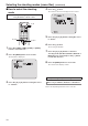
Recording to and playing back from a memory card The unit can record and playback in MP4 format to/from the following SD cards compliant with the SD standards. ●● Set the priority mode to “SD card” before use. For details, refer to “Priority mode tab [Priority Mode]” (page 65). Inserting and ejecting an SD card (optional accessory) Connector panel Notes ●● IP control, IP video transmission, and PoE+ power supply can be used at the same time as these functions if you use a LAN cable.
Recording to and playing back from a memory card 4. Start and stop recording by clicking the [Rec] button and [Stop] button of the “SD Card Operation” item. (continued) ●● If the web screen is updated during recording, display becomes the Other menu of the Live screen. ●● When the unit records to a microSDHC memory card, it usually splits the recording into 4 GB files.
Recording to and playing back from a memory card Playing Back (continued) Play List screen Select content individually. Select all content. Switches to top page. Returns to the previous page. Goes to the next page. Switches to last page. Displays the number of pages. 1. Click the [Play List] button of the “SD Card Operation” item. Displays the recording start date and time of the content. Displays the recording duration of the content.
Recording to and playing back from a memory card (continued) Downloading a file Click this button on the playback screen to download the file currently playing back to the connected personal computer. Specify the save destination on the personal computer. ●● If downloading does not start and no operation is performed for a while, downloading may not be possible. If the file could not be downloaded, click again to start downloading. Notes 3.
Web camera functions The unit can be used as a Web camera if you connect the unit and a personal computer or other device with a commercially available USB cable. The unit is compliant with USB Video Class and USB Audio Class. The video and audio of the unit can be transmitted to a personal computer or other device by using communication software or other software. ●● Set the priority mode to “USB” before use.
Web camera functions (continued) Camera control [Camera Control] Zoom [Zoom] This allows you to enlarge (zoom in) and reduce (zoom out) images. Setting range: 1 (wide end) to 2731 (optical telephoto end) Focus [Focus] The lens focus can be adjusted manually. Setting range: 1 (Near) to 2731 (Far) ●● This cannot be controlled when the focus mode is “Auto”. ●● If this item is set to auto mode, the focus mode is set as “Auto”. Also, if auto mode is canceled, the focus mode is set as “Manual”.
Web camera functions (continued) Audio input mixer [Audio Input Mixer Properties] Enable/Disable (Mute) [Enable] The audio input signal from the device connected to the audio input connector can be turned off or on in the same way as “Audio” of the camera menus and Web settings. Setting value: 0 (Off), 1 (On) Notes ●● In USB priority mode, H.264 image transmission cannot be performed for IP video. ●● When the device is connected by USB, the IP video JPEG(1) setting is forcefully changed to 320×180/5fps.
Displaying the web screen using a mobile terminal Connect the mobile terminal to the unit, and display the unit’s images (MJPEG format only). Refreshing to the latest images takes place automatically. Operations such as panning, tilting and zooming can also be performed from the mobile terminal. The following models are supported as mobile terminals. (as of May 2015). Mobile terminal Pan/Tilt Specifications iPad iPhone iPod touch iOS 8.3 Android™ terminals Android 4.
Displaying the web screen using a mobile terminal (continued) Preset Resolution switching When this button is pressed, the buttons for selecting the preset positions are displayed on the screen. When one of the displayed buttons is pressed, the camera’s pan/tilt position moves to the preset position that was registered ahead of time. The settings that are reproduced at this position are the settings which were established on the [Preset Scope] menu (page 46, page 81, page 83).
Displaying the web screen using a mobile terminal (continued) Iris Focus When this button is pressed, the buttons for performing the iris operations are displayed on the screen. This switches the iris between auto and manual. At the auto setting, the button label is green. This adjusts the iris in the “close” direction. It does not work during automatic adjustments. This adjusts the iris in the “open” direction. It does not work during automatic adjustments.
Displaying the web screen using a mobile terminal (continued) Camera menu (OSD menu) operation When this button is pressed, the buttons for performing the camera menu operations are displayed on the screen. At the same time, the camera menus are also displayed on the monitor images of the unit. The unit’s camera menu operations can be performed by pressing the , , and buttons.
Limiters The unit comes with settings (referred to as “limiters”) that restrict the panning and tilting movement ranges. Depending on where the unit has been installed, a subject which the user does not wish to be shot may be present in the movement ranges. In a case like this, the unit’s shooting range can be limited by setting the limiters at the positions just before the subject which the user does not wish to be shot.
Limiters (continued) ■■Setting the limiters ■■Releasing the limiters The limiter positions can be set by following the steps below. When the position is set, the tally lamp blinks once. The limiter positions that are set can be released by following the steps below. When the position is released, the tally lamp blinks twice. 1 Press one of the [CAM1] to [CAM4] buttons to select the unit.
Activation AW‑SFU01 (optional accessory) is required to perform activation. Perform activation as described below. 1. Checking whether activation has been performed 2. Obtaining the activation code Obtaining the activation code The activation code can be obtained by accessing the activation code generation site and then having the serial number information of the unit and key code included with AW‑SFU01 authenticated. 1. Click [Setup] [Maintenance] [Activate] from the Web screen. 3.
Activation (continued) Activating the unit Checking that activation is complete 1. Click [Setup] [Maintenance] [Product info.] from the Web screen. 1. Click [Browse] of the “Upload” item and then specify the folder in which the obtained “ACTIVE.LST” is stored. 2. Click the [Execute] button of the “Upload” item. 3. Click the [OK] button. After uploading completes, the unit restarts automatically. 4. Click the [OK] button. The web screen appears. 2.
Troubleshooting ●●Operation Symptom Cause and remedial action Reference pages ●● Is the AC adaptor securely connected to the AC outlet? ––– ●● If the power plug of the AC adaptor connected properly? ––– ●● Is the network cable for the PoE+ (IEEE802.3at) compatible power supply device and the unit connected properly? P.35 ●● Power may not be supplied if the total power limit is exceeded on power supply devices that allow connections to multiple PoE+ terminals.
Troubleshooting Symptom The unit turns in the opposite direction to the one operated (continued) Cause and remedial action ●● Has the stand-alone (Desktop) installation setting been selected correctly? ●● The reversal setting may have been established at the controller if the unit is connected to the controller. Refer to the Operating Instructions of the controller. Reference pages P.46, P.
Troubleshooting Symptom (continued) Cause and remedial action ●● Are you accessing via “http://” while the HTTPS function is enabled? Perform access via “https://” when using the HTTPS function. Entry of the port number is also required. No access is possible from the web browser P.51, P.89 ●● Does the subnet mask setting match the network subnet of the connection destination? Check out the subnet mask settings of the unit and access devices, and then consult with the network administrator. P.
Troubleshooting (continued) ●●Video/Audio Symptom Cause and remedial action ●● Has the unit been connected properly to the other connected devices? No pictures are displayed or the pictures are disturbed ●● If the system is configured in such a way that the picture is also switched when the unit to be operated is selected, has the correct unit been selected? Reference pages P.18 to 25 P.9 ●● Has the video signal setting been selected correctly? P.44, P.
Troubleshooting (continued) Symptom Cause and remedial action Reference pages The images appear jerky when the 1080/29.97PsF or 1080/25PsF format is selected ●● Operation is problem-free. What happens with the PsF (progressive segmented frame) system is that the same images as the progressive system are output by recording the same images in field 1 and field 2 so that the resulting images may appear somewhat jerky. ––– ●● Activate the ATW (Auto tracking white adjustment) function. P.
Troubleshooting (continued) Symptom Cause and remedial action Reference pages The brightness changes cyclically or the colors change, and horizontal stripes can be seen passing across the screen ●● These phenomena (flicker) may occur under the illumination produced by fluorescent lighting, mercury bulbs or other types of discharge tubes. In cases like this, it is recommended that the electronic shutter speed be set as follows. When the Frequency is set to “59.
Troubleshooting (continued) ●●IP videos Symptom Cause and remedial action [When using Windows] ●● Is the plug-in viewer software installed? Install the plug-in viewer software. No images are displayed The images are not refreshed P.48 [When using Windows] ●● If “Every time I visit the webpage” is not selected for “Check for newer versions of stored pages” in the Temporary Internet Files settings, the IP videos on the Live screen may not be displayed properly. Follow the steps below.
Troubleshooting Symptom (continued) Cause and remedial action [When using Windows] ●● Press the [F5] key on the keyboard of the personal computer to request that the settings be acquired. [When using Mac] ●● Press the [Command] + [R] keys on the keyboard of the personal computer to request that the settings be acquired. Reference pages ––– ●● Follow the steps below to delete the temporary Internet files (Cache). [When using Windows] A In Internet Explorer, select [Tools] [Internet Options].
Troubleshooting Symptom The authentication screen appears repeatedly (continued) Cause and remedial action Reference pages ●● Has the user name or password been changed? If you change the user name and password of the user currently logged in from a separate web browser while the unit is being accessed, the authentication screen appears each time the screen display is changed. Close the web browser, and initiate access to the unit again. P.
Troubleshooting Symptom When multiple web browsers are running to display H.264 images, images from multiple cameras appear sequentially in a single web browser.
Troubleshooting (continued) ●●Web browser settings Depending on the OS installed on the personal computer, the following may occur. Follow the instructions below when the following has occurred. By performing the following solutions, other applications and the security level may not be affected. [When using Windows] The “information bar” described in the following explanations refers to the message bars that appear in Internet Explorer. For Internet Explorer 9.0, 10.0, and 11.
Index Numerics 16-axis color matrix ........................................................... 42 A Access level ................................................................. 87, 88 Activate ............................................................................ 108 Activation ........................................................................... 88 Activation counter ............................................................ 105 Advanced ...................................................
Index (continued) G Gain ..................................................................... 37, 75, 113 Gamma ............................................................................ 113 Gamma Level .............................................................. 40, 78 Gamma Type ............................................................... 40, 78 H H.264(1) • H.264(2) • H.264(3) • H.264(4) ......................... 69 H.264 transmission ...........................................................
Index (continued) Preset Setting .................................................................... 81 Preset Speed ......................................................... 46, 81, 83 Preset Speed Table ............................................... 46, 81, 83 Primary DNS server address ............................................. 90 Primary server address ..................................................... 90 Priority Mode ...........................................................
Web Site: http://www.panasonic.