Operating Instructions Indoor Pan-tilt Head Model No. AW-PH405N Before operating this product, please read the instructions carefully and save this manual for future use.
Safety precautions FCC Note: This equipment has been tested and found to comply with the limits for a class A digital device, pursuant to Part 15 of the FCC Rules. These limits are designed to provide reasonable protection against harmful interference when the equipment is operated in a commercial environment. This equipment generates, uses, and can radiate radio frequency energy, and if not installed and used in accordance with the instruction manual, may cause harmful interference to radio communications.
Safety precautions IMPORTANT SAFETY INSTRUCTIONS Read these operating instructions carefully before using the unit. Follow the safety instructions on the unit and the applicable safety instructions listed below. Keep these operating instructions handy for future reference. 1) Read these instructions. 10) Protect the power cord form being walked on or pinched particularly at plugs, convenience receptacles, and the point where they exit from the apparatus. 2) Keep these instructions.
Contents Safety precautions ................................................................................................................................................. 2 Operating precautions . ......................................................................................................................................... 5 Introduction ............................................................................................................................................................
Operating precautions Handle the unit carefully. Do not use the unit outdoors. Dropping the unit or subjecting it to strong impact may give rise to malfunctioning or accidents. Maintenance Wipe the unit using a dry cloth. To remove stubborn dirt, dip a cloth into a diluted solution of kitchen detergent, wring it out well, and wipe the unit gently. Turn off the power before connecting or disconnecting the cables.
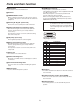
Accessories Operating instructions ...................................................... Rotary arm ......................................................................... Camera mounting base . ................................................... Mounting screws for the rotary arm and camera mounting base (with flat washers, spring washers) M522 mm . ............................................................ Camera cable .....................................................................
Parts and their function
Parts and their function Rotary head PROMPTER connector This rotates in the horizontal direction. The prompter is connected to this connector. The maximum current which can be supplied from the DC 12 V OUT socket is 2.5 A. When the prompter is connected, the pan-tilt head’s speed is reduced to about one-third. When connecting the prompter, be absolutely sure to short-circuit the DETECT terminal (Pin No.14) and the GND terminal (Pin No.15).
Parts and their function Rotary head connector panel ND/EXT connector [ND/EXT] LENS P/S ON/OFF switch [LENS P/S] This is for the control of the ND filter and lens extender of the motorized lens unit. Connect this connector when using a motorized lens unit with ND filter and lens extender functions. The cable described in “Cable specifications” on page 26 is required in order to connect this connector.
Parts and their function Pedestal connector panel CONTROL IN RP connector [RP] AUX connector [AUX] This is the connector for the control of signals of the camera and pan-tilt head. It is connected to the TO PAN/TILT HEAD connector on the AW-RP655 multi-function controller and AW-RP555 multi hybrid control panel. Use a 10BASE-T (equivalent to UTP category 5) straight cable for the connecting cable. This is the output connector for the camera’s video signals.
Installation Assembling the pan-tilt head When assembling the pan-tilt head, use the Allen key (provided) and screwdriver, and secure the head by tightening the screws firmly. After mounting the pan-tilt head, check there is no play in its installation. Attaching the camera mounting base Attach the camera mounting base to the rotary arm using the three mounting screws (M522 mm, with flat washers, spring washers) provided. The installation direction differs depending on how the base is installed.
Installation Mounting the tally lamp Connect the cable connector which is taped to the top of the pan-tilt head to the tally cable connector. Mount the tally lamp on the top of the pan-tilt head using the two screws provided. Mount the lamp while paying attention to the wire. The cable for the tally cable connector is about 2-1/16” (50 mm) long. When connecting the cable to the connector, do not pull it out beyond this length.
Installation Concerning the safety modes This unit comes with two safety modes which are designed to safeguard the user and others from injury and to prevent damage to the pan-tilt head. 1. Mode for ensuring safety in the case of collisions When the rotary arm of the pan-tilt head or some other unit installed on the head keeps colliding with an obstruction or a person (approx. 6 seconds when the head rotates at 45 degrees per second), the mode for ensuring safety in the case of collisions is established.
Installation Procedure for changing the settings of the CPU circuit board switches Follow the steps below to change the settings of the CPU circuit board switches. Remove the four screws, and gently remove the housing case. Disconnect the tally cable connector. Set the switches on the CPU circuit board. After you have performed the settings, connect the tally cable connector, and then return the housing case to its original position, and attach it using the screws.
Installation Setting the CPU circuit board switches CPU circuit board Magnification of the CPU circuit board Setting SW1 These switches are used to set the operations of the AW-PH405. Before changing their settings, make sure that the power has been turned off. No.1: Auto focus (AF)/extender (EXT) selector switch.
Installation Pan-tilt head mounting conditions Pan-tilt Mounting head weight specifications Approx. 22 lbs (10 kg) Stand-alone installation or installation on the celling Compatible cameras Camera weight Convertible camera series AW-E350 AW-E650 AW-E655 AW-E750 AW-E860 Approx. 2.6 lbs (1.2 kg) max. Multi-purpose camera series AK-HC1500G Approx. 3.3 lbs (1.
Installation For a stand-alone installation Note For installation on the ceiling When installing the pan-tilt head, do not forcibly turn the rotary head or rotary arm manually. Doing so may result in malfunctioning.
Installation Mounting the camera [Convertible camera AW-E350/E650/E655/E750/E860] When mounting the camera, take sufficient care to ensure that the camera will not come off or fall down. Mount the lens onto the convertible camera. (Before mounting a large lens, consult with your dealer.) Mount the convertible camera after aligning it with the guide pins. Use a tool to tighten up the mounting screws so that they are securely tightened. For a stand-alone installation Set the guide pin.
Installation Attaching the wire [Convertible camera AW-E350/E650/E655/E750/E860] The camera comes with a wire for preventing the camera from dropping. Follow the instructions below to use it to couple the camera to the pan-tilt head. When mounting the cameras with fan (AW-E655, AW-E750, AW-E860) Use the wire mounting screw (M48 mm with flat washer and spring washer) to attach one end of the wire to the pan-tilt head’s arm. Mount the mounting spacer on the top panel of the camera.
Installation Mounting the camera [Multi-purpose camera AK-HC1500G] When mounting the camera, take sufficient care to ensure that the camera will not come off or fall down. Mount the lens onto the multi-purpose camera. (1) Lenses that can be used • Use any of the portable lenses which are listed below.
Installation Concerning the balance of the installed unit The weight balance may be impaired when the pan-tilt head is used in combination with a camera and long lens. Follow steps to 3 below to check the balance, and then mount the camera. If, after this, the balance is still impaired and operations cannot be performed smoothly, it means that the balance must be adjusted. Consult your dealer.
Installation Precautions for mounting the camera Bearing in mind the length of the lens, set the movement range of the pan-tilt head using the limiters in such a way that the hood at the edge of the lens will not come into contact with the surface on which the pan-tilt head is installed when the pan-tilt head is tilted. Note To point the lens any further straight down in a stand-alone installation, insert a spacer between the pan-tilt head and mounting surface to raise the pan-tilt head position.
Installation Attaching the wire [Multi-purpose camera AK-HC1500G] The camera comes with a wire for preventing the camera from dropping. Follow the instructions below to use it to couple the camera to the pan-tilt head. Use the wire mounting screw (M48 mm with flat washer and spring washer) to attach one end of the wire to the pan-tilt head’s arm. Use the wire mounting screw (Inch screw with flat washer and spring washer) to attach the other end of the wire on the top panel of the camera.
Connections Turn off the power of all the equipment before proceeding with the connections. Connect the AC power cable supplied with the AW-PH405 for the AW-PH405 indoor pan-tilt head. Use 10BASE-T straight cables to connect the RP connectors on the pan-tilt heads with the CONTROL OUT TO PAN/TILT HEAD (1 to 5) connectors on the AW-RP655 multi-function controller and AW-RP555 multi hybrid control panel.
Connections For the AK-HC1500G Note Set the menu items to protocol 4.
Cable specifications When connecting a Canon lens with motorized extender unit Connector: HR10A-10P-10P (73) made by Hirose Electric Connector: H R10A-7P-6S (73) made by Hirose Electric CVCC (12 V) CGND EXT Return EXT Signal ND Return ND Signal CanonEXT () SHELL CanonEXT () GND Connect this connector to the EXT connector on the lens GND SHELL Connect this connector to the ND/EXT connector on the pan-tilt head When connecting a Fujinon extender change unit Connector: H R10A-7P-5P (73) made by
Replacing the consumable parts Replacing the motor Replace the motor when it ceases to operate properly. For details on the motor replacement, consult your dealer. Replacing the belt Replace the belt when the preset stop accuracy has deteriorated. For details on the belt replacement, consult your dealer. Replacing the gear Replace the gear when the preset stop accuracy has deteriorated. For details on the gear replacement, consult your dealer. The motor, gear and belt are consumables.
Appearance Unit: inch (mm) 12-9/16 (319) 5-3/8 (137) 7-3/16 (182) 2-13/16 3-13/16 (71) (97) 1-7/8 (47) 8-1/4 (209) 16-3/8 (416) 6-1/2 (165) 1-5/8 (42) 6-5/8 (168) ø6-5/16 (160) ø6-5/16 (160) ø5-3/4 (146) ø5-3/4 (146) ø6-5/16 (160) 4-M6 screws 28
Specifications Supply voltage: AC 120 V, 60 Hz Power consumption: 120 W indicates safety information.
Memo ———————————————————————————————————————————— ———————————————————————————————————————————— ———————————————————————————————————————————— ———————————————————————————————————————————— ———————————————————————————————————————————— ———————————————————————————————————————————— ———————————————————————————————————————————— ———————————————————————————————————————————— ———————————————————————————————————————————— ———————————————————————————————————————————— ———————————————————————————————————————————— ———————————
Memo ———————————————————————————————————————————— ———————————————————————————————————————————— ———————————————————————————————————————————— ———————————————————————————————————————————— ———————————————————————————————————————————— ———————————————————————————————————————————— ———————————————————————————————————————————— ———————————————————————————————————————————— ———————————————————————————————————————————— ———————————————————————————————————————————— ———————————————————————————————————————————— ———————————
PANASONIC BROADCAST & TELEVISION SYSTEMS COMPANY UNIT COMPANY OF PANASONIC CORPORATION OF NORTH AMERICA Executive Office: One Panasonic Way 4E-7, Secaucus, NJ 07094 (201) 348-7000 EASTERN ZONE: One Panasonic Way 4E-7, Secaucus, NJ 07094 (201) 348-7621 Southeast Region: 1225 Northbrook Parkway, Ste 1-160, Suwanee, GA 30024 (770) 338-6835 Central Region: 1707 N Randall Road E1-C-1, Elgin, IL 60123 (847) 468-5200 WESTERN ZONE: 3330 Cahuenga Blvd W.