Operating Instructions Multi-Format Monitor Model BT-H1700AE MUTING DEGAUSS UNDER SCAN PULSE CROSS COLOR OFF MENU BLUE CHECK ASPECT AREA MARKER SLOT 1 A VOLUME BEDIENUNGSANLEITUNG MANUEL D’INSTRUCTIONS MANUALE DI ISTRUZIONI INSTRUCCIONES : : : : SLOT 2 B C POWER SLOT 3 D E F INPUT SELECT MULTI-SYSTEM-MONITOR MONITEUR MULTI-FORMAT MONITOR MULTI-FORMATI MONITOR MULTIFORMATO Before attempting to connect, operate or adjust this product, please read these instructions completely.
LCT1261-001A (EN) 2 02.6.
MULTI-FORMAT MONITOR BT-H1700AE Thank you for purchasing this Panasonic multi-format monitor. Before using it, read and follow all instructions carefully to take full advantage of the monitor’s capabilities. For Customer Use: Enter below the Serial No. which is located on the rear of the cabinet. Retain this information for future reference. Model No. : BT-H1700AE Serial No. : CONTENTS SAFETY PRECAUTIONS ........................................................................ 2 CONTROLS AND FEATURES .
SAFETY PRECAUTIONS In order to prevent any fatal accidents caused by misoperation or mishandling the monitor, be fully aware of all the following precautions. WARNING : THIS APPARATUS MUST BE EARTHED. WARNINGS To prevent fire or shock hazard, do not expose this monitor to rain or moisture. Dangerous high voltages are present inside the unit. Do not remove the back cover of the cabinet. When servicing the monitor, consult qualified service personnel. Never try to service it yourself.
ENGLISH For Your Safety Caution for AC Mains Lead FOR YOUR SAFETY PLEASE READ THE FOLLOWING TEXT CAREFULLY. This product is equipped with 2 types of AC mains cable. One is for continental Europe, etc. and the other one is only for U.K. Appropriate mains cable must be used in each local area, since the other type of mains cable is not suitable. FOR CONTINENTAL EUROPE, ETC. Not to be used in the U.K. FOR U.K.
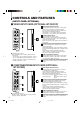
CONTROLS AND FEATURES FRONT VIEW 1 2 3 4 5 7 8 11 12 13 14 MUTING DEGAUSS UNDER SCAN PULSE CROSS COLOR OFF VOLUME MENU SCREENS CHECK ASPECT AREA MARKER 18 19 20 21 22 23 SLOT 1 A UNDER SCAN PULSE CROSS COLOR OFF MENU BLUE CHECK ASPECT AREA MARKER SLOT 1 SLOT 2 B C E E F F 1 Tally lamp 9 10 15 16 17 8 EMBEDDED AUDIO channel switch button 2 PHASE adjustment knob Adjusts picture hue.
REAR/SIDE VIEW ENGLISH REMOTE MAKE SLOT2 26 27 SLOT3 SLOT1 RS-232C 30 28 MAIN POWER 29 14 COLOR OFF button/lamp Press the COLOR OFF button. The button lights and the screen becomes monochrome. When the COLOR OFF button is pressed while lit, the light goes off and the normal screen is restored. Use this function to confirm the noise in the brightness signal or to confirm the white balance. NOTE: This function is invalid with the RGB-input screen.
CONTROLS AND FEATURES (INPUT CARD: OPTIONAL) 䡵 VIDEO INPUT CARD (OPTIONAL: BT-YA701P) 1 Video input/output terminals Input (IN) and output (OUT) terminals for video signals. The IN and OUT terminals are bridge-connected. (When no cable is connected to the OUT terminal, the input signal is automatically terminated.) Select VIDEO 1 : press INPUT SELECT A/C/E button Select VIDEO 2 : press INPUT SELECT B/D/F button VIDEO 1 IN OUT VIDEO 2 1 2 S-video input terminal OUT IN Y/C IN 2 EXT.
ENGLISH 䡵 SDI INPUT CARD (OPTIONAL: BT-YA703P) 1 Output terminal for a selected component serial digital signal Output terminal for a selected digital signal (the input displayed on the screen). The output signal is cablecompensated. NOTE: When the monitor’s power is OFF, no digital signal is output. SWITCHED OUT 1 IN SDI 1 2 IN 4 SDI 2 AUDIO 1 2 Input terminals for component serial digital signals Input terminals for the digital signal.
PREPARATION 䡵 INSTALLING THE INPUT CARD 䡵 ATTACHING THE WIDE MASK Optional input cards are necessary to use the functions of this monitor. Before mounting the monitor or connecting other equipment to the monitor, be sure to install the input cards. A wide mask is provided with the monitor. This changes the viewable screen area to the 16:9 aspect ratio. The wide mask cannot be attached to the monitor after the monitor is mounted in a rack. Mount the wide mask before installing the monitor in a rack. 1.
ENGLISH 䡵 ATTACHING THE POWER CORD HOLDER The provided Power Cord Holder prevents accidental disconnection of the AC power cord from the AC inlet. The Power Cord Holder consists of two parts; a case and cover. 1. Attach the Power Cord Holder case to the AC inlet on the back of the monitor with 2 screws (provided). Caution: Use only the provided screws. 2 Attach the Power Cord Holder cover to the AC power cord. Press the cover until it clicks. 3.
BASIC MENU OPERATIONS (MAIN MENU, SETUP MENU) 䡵 ABOUT MENU SCREENS This monitor features a MAIN MENU (main menu screen) and a SETUP MENU (setup menu screen). The MAIN MENU contains the functions normally used, and the SETUP MENU contains the settings required for initial setup. APERTURE CONTROL SLOT CONDITION sub menu POSITION AREA MARKER AREA MARKER-R CENTER MARKER COLOR MATRIX FUNCTION SETTING PICTURE SUB ADJ. COLOR TEMP/BAL. SIZE/POSI.ADJ. DISTORTION ADJ.
HOW TO USE “MAIN MENU” ENGLISH 䡵 “MAIN MENU” ITEMS The following items appear in MAIN MENU. Items Functions Displays 1 APERTURE CONTROL Compensates the frequency characteristics of the input video signal. 2 SLOT CONDITION Displays the status of the input cards installed in each of the input card slots. 3 sub menu POSITION Selects the display position of the sub menu superimposed on the screen. 4 AREA MARKER Selects the size marker for the other screen ratio used when the screen ratio is 16:9.
HOW TO USE “MAIN MENU” (cont'd) 䡵 ITEM CONTENTS AND ADJUSTMENT RANGE/SETTINGS 1. APERTURE CONTROL Compensates the frequency characteristics of the input video signal. Press the button to display the setting menu illustrated on the right. NOTE : APERTURE CONTROL is not displayed when the RGB signal is input. LEVEL CONTROL FREQ. sub menu reset : 00 :HIGH EXIT: MENU ADJUST:- + SELECT: HD SDI 1 or HD SDI 2 shows the HD SDI input card is installed.
: Selects the size marker for the other screen ratio (aspect) used when the screen ratio is 16:9. (for external control) Settings : OFF/16:9/4:3/13:9/14:9/MODE 1/MODE 2 Functions : OFF: The marker is not displayed. 16:9/4:3/13:9/14:9: Displays the marker (a white quadrangle) showing the screen size of each aspect ratio. MODE 1/MODE 2: Displays no markers because these settings will be used for function expansion in the future.
HOW TO USE “SETUP MENU” 䡵 “SETUP MENU” ITEMS Items Functions 1 FUNCTION SETTING Displays the monitor’s power-up time or the total usage time. 2 PICTURE SUB ADJ. Performs approximate adjustments using the control knobs on the front panel. 3 COLOR TEMP./BAL. Sets or adjusts the colour temperature or white balance. 4 SIZE/POSI. ADJ. Adjusts the size or position of the picture. 5 DISTORTION ADJ. Compensates the picture distortion.
1. FUNCTION SETTING Selects the colour system and displays the monitor’s powerup time or the total usage time. button to display Press the the setting menu illustrated on the right. COLOR SYSTEM SYNC SELECT RUSH DELAY TIME TALLY SELECT REMOTE SYSTEM EMBEDDED HOUR METER X100h :AUTO :INT. :STD. :GREEN :MAKE :1G :000 Item Settings Function : REMOTE SYSTEM : MAKE/TRIGGER : Selects the contact system (MAKE (make contact) or TRG. (trigger contact)) for the MAKE/ TRIGGER terminals.
HOW TO USE “SETUP MENU” (cont'd) Item : CONTRAST Adjustment range : –20 ~ 00 ~ +20 Function : For approximate adjustment of the picture contrast. Before adjustment, turn the CONTRAST knob on the front panel to the middle. Item : BRIGHT Adjustment range : –20 ~ 00 ~ +20 Function : For approximate adjustment of the picture brightness. Before adjustment, turn the BRIGHT knob on the front panel to the middle.
5. DISTORTION ADJ. Adjusts the size or position of the picture. Press the button to display the setting menu illustrated on the right. H.SIZE H.POSITION V.SIZE V.POSITION sub menu reset : : : : 00 00 00 00 Compensates the picture button distortion. Press the to display the setting menu illustrated on the right. EXIT: MENU ADJUST:- + SELECT: Item : H.SIZE Adjustment range : –20 ~ 00 ~ +20 (*) Function : Adjusts the horizontal screen size. – : Reduces the screen size horizontally.
HOW TO USE “SETUP MENU” (cont'd) 6. STATUS DISPLAY 7. CONTROL LOCK Makes the status of the input signal appear or disappear on the screen. Press the button to display the setting menu illustrated on the right.
ENGLISH HOW TO USE EXTERNAL CONTROL 䡵 ABOUT EXTERNAL CONTROL The Multi-Format Monitor has two external control terminals. One is the MAKE/TRIGGER terminal, which allows the monitor to be controlled by the MAKE(make contact) or TRG. (trigger contact) method selected in the function setting. MAKE (make contact system): Controls the function by stable disconnection (terminal open) or short-circuiting (short with GND of 15th terminal) of the controlled terminal. TRG.
HOW TO USE EXTERNAL CONTROL (cont'd) 䡵 HOW TO USE THE RS-232C TERMINAL You can control the monitor from your PC via the RS-232C terminal. For details on operating the monitor from the PC, consult your dealer or service centre for details. 9 8 7 6 1. Cable Prepare a straight cable with a D-sub connector (9-pin, female) and a D-sub connector (9-pin, male) 5 4 3 2 1 2.
TROUBLESHOOTING Problems No power supply No picture with the power on No sound Wrong colour Unnatural picture Shaking picture Points to be checked Measures (Remedy) Reference pages Is the power plug loosened or disconnected? Firmly insert the power plug. Is the main power turned OFF? Turn the main power ON. Is the signal cable disconnected? Connect the signal cable firmly.
TROUBLESHOOTING (cont’d) Points to be checked Measures (Remedy) Reference pages Is the monitor placed or moved close to a speaker or any other device incorporating a magnet? Has the position of the monitor been changed with the power on? Move the device away from the monitor. Press the DEGAUSS button on the front panel to degauss the screen. When degaussing, wait more than 30 minutes for maximum effect.
ENGLISH 䡵 SELF-CHECK INDICATIONS When the screen goes blank, and one or more of the INPUT SELECT A through F buttons on the front control panel start blinking... This monitor has a self-check function, which allows it to detect malfunctions and alert you. This makes trouble-shooting easier. Whenever a problem occurs, a combination of “self-check indicators” (INPUT SELECT A through F buttons) will blink and the monitor’s power automatically turns off.
SPECIFICATIONS 䡲 Type : Multi-Format Monitor 䡲 Picture Tube : 17" measured diagonally 䡲 Effective Screen Size : Width : 330 mm Height : 250 mm Diagonal : 410 mm 䡲 Scanning Frequency : H : 15 kHz/27 kHz – 45 kHz V : 50 Hz – 80 Hz 䡲 Video Band : Component : 25 MHz (–3 dB) Video (Y/C) : 8 MHz (–3 dB) 䡲 Horizontal Resolution : Video (Y/C) : 600 TV lines 1080/60i : 800 TV lines 䡲 Input Terminals : Installing an optional input card in SLOT 1, 2, or 3 is required.
Input Signals BT-YA701P BT-YA702P BT-YA703P BT-YA705G — — — — — — Black-and-White (50 Hz/60 Hz) R R R — — — 480/60i (525i) — R — 480/60p (525p) — 576/50i — 576/50p — 720/60p (720p) — 1080/50i — 1080/60i (1125i) (*2) — 1035/60i (1125i) (*1 *3) — 1080/24psF (*4) — R R R R R R R 䡬 R EMBEDDED AUDIO — — NTSC (3.58 MHz) PAL (4.43 MHz) — — R — — — — R R R 䡬 R R — — — — — ENGLISH 䡵 Compliant Signal Formats of Each Input Card R : Input possible. Pre-set.
SPECIFICATIONS (INPUT CARD: OPTIONAL) 䡵 BT-YA701P: VIDEO INPUT CARD Type Inputs/Outputs : Video input card for Multi-Format Monitor : VIDEO 1/VIDEO 2: 2 lines, BNC connector x 4 (1 V (p-p), 75 Ω) Synchronised signal (EXT.SYNC): 1 line, BNC connector x 2 (1.0 V – 4.0 V (p-p), 75 Ω) * The input (IN) and output (OUT) terminals are bridge-connected. Auto termination. Y/C signal : 1 line, input only, mini-DIN 4-pin connector x 1 (Y/C input has a priority to a VIDEO 2 input) (Y: 1 V (p-p), 75 Ω/C: 0.
Matsushita Electric Industrial Co.,Ltd. Web Site: http://www.panasonic.co.jp/global/ Printed in Japan VQT0A55-1 LCT1261-001B (EN) LCT1261-001B 0802-PN-Y-U-VP 32 02.08.