Operating Instructions LCD Video Monitor Model BT- P Before operating this product, please read the instructions carefully and save this manual for future use.
g THIS EQUIPMENT MUST BE GROUNDED To ensure safe operation, the three-pin plug must be inserted only into a standard three-pin power outlet which is effectively grounded through normal household wiring. Extension cords used with the equipment must have three cores and be correctly wired to provide connection to the ground. Wrongly wired extension cords are a major cause of fatalities.
For Your Safety (continued) FCC NOTICE (USA) Declaration of Conformity Model Number: BT-LH1700WP Trade Name: PANASONIC Responsible Party: Panasonic Corporation of North America One Panasonic Way, Secaucus, NJ07094 Support contact: Panasonic Broadcast & Television Systems Company 1-800-524-1448 This device complies with Part 15 of FCC Rules.
Precautions for Use • The liquid crystal portion is manufactured with highly precise technology. It includes over 99.99% effective pixels, but 0.01% or less of the pixels are either missing, or have fixed lighting (red, blue, green). This is not a sign of malfunction. • The liquid crystal protection panel is a specially manufactured component. Wiping it with a hard cloth, or rubbing it vigorously will scratch the surface.
Outline The BT-LH1700W liquid crystal monitor was designed especially for broadcasting service and business use. It is equipped with a high performance 17.1-inch wide liquid crystal display panel. g High performance liquid crystal panel This monitor achieves outstanding color reproduction, a wide viewing angle, and high-speed response.
Controls and Their Functions Video monitor unit Front view Front panel (J page 7) Rear view Fan An embedded audio unit (BT-YAE1700G) can be attached (J Installation Guide included).
Front panel POWER switch This switches the power supply ON/OFF. When the power is ON, the LED (green) lights up. INPUT SELECT button This selects the signal input line. The green LED light above the button indicates the selected input signal. VIDEO : Video input Y/C : Y/C input SDI1 : Serial digital interface input (HD/SD compatible) SDI2 : Serial digital interface input (HD/SD compatible) YPBPR/RGB : Analog component (YPBPR) or RGB input. Also compatible with PC input RGB.
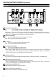
Controls and Their Functions (continued) Rear panel 1 2 3 6 4 7 5 8 SDI (HD/SD) terminal (BNC) IN1 : This is the SDI input terminal (compatible with HD/SD automatic switching). IN2 : This is the SDI input terminal (compatible with HD/SD automatic switching). SWITCHED OUT : This is the active through-out terminal for the SDI input signal being displayed on the screen. * SDI active through-out is only outputted when [SDI1] or [SDI2] is selected using the [INPUT SELECT] buttons.
Power Supply Connecting and fixing the power cord 1. Attach the power cord to the monitor unit. Using the power cord hook and the screw, attach the power cord to the monitor unit. g When using external DC power (DC11V–17V) You can slide open the power cover, and switch from AC input to external DC input. (When shipped from the factory, the power cover is up, and AC input is selected.) Power cover Power cord Power cord hook Screw 2. Connect the power cord to the power outlet.
How to Use the On Screen Menu Three types of information are displayed on the screen. The input signal status, picture adjusting knob status, and the menu display. Input signal status 1 1. The selected input line (J page 7, ) • VIDEO, Y/C, SDI1, SDI2, YPBPR/RGB-VIDEO/RGB-COMP. 2. Signal format • The display status can be set in “STATUS DISPLAY” in the “SYSTEM CONFIG” menu (J page 18).
How to Use the On Screen Menu (continued) Menu operations 1. Push [MENU] to display the MAIN menu. 3. Push [ , ] to select the sub menu, then push [ENTER]. The setting values in the sub menu change to green. MARKER MARKER 16:9 MARKER 4:3 MARKER BACK CENTER MARKER GPI PRESET1 GPI PRESET2 2. Push [ , [ENTER]. OFF OFF NORMAL OFF 80% 80% ] to select the menu, then push 4. Push [ , ] to select the setting values, then push [ENTER]. Push [MENU] to cancel.
User Data You can change the menu setting values and picture adjusting knob settings, then save and load up to 5 combinations of screen adjustment values as user data. You can also return the setting values and adjustment values to the factory preset settings. The following settings are included in user data.
Menu configuration MAIN MARKER 16:9 MARKER VIDEO CONFIG SYSTEM CONFIG MARKER 4:3 GAMMA SELECT BACKLIGHT FILM GAMMA FUNCTION1 COLOR TEMP.
Main Menu (continued) MARKER The underlined values are factory preset setting values. Sub menu MARKER 16:9*1*2 MARKER 4:3*1*3 Settings <4:3 > <13:9> <14:9> <95%> <93%> <90%> <88%> <80%> <95%> <93%> <90%> <88%> <80%> Explanation Used to select/display the type of marker when the aspect ratio setting is 16:9. <4:3> <14:9> <93%> <88%> Marker not displayed.
Main Menu (continued) Types of MARKER g 16:9 marker (Displayed when using HD, or when using SD with a 16:9 aspect ratio) The marker is only displayed as a vertical bar. In addition, the section becomes the “MARKER BACK” item. 4:3 marker Area marker A dotted line is displayed as the marker. 95% Area marker 93% Area marker 90% Area marker 88% Area marker 13:9 marker 14:9 marker VISTA marker, CNSCO marker A horizontal dotted line is displayed as the marker.
Main Menu (continued) VIDEO CONFIG The underlined values are factory preset setting values. Sub menu GAMMA SELECT*2 Settings Explanation *1 Used to select the gamma curve. When FILM is selected, left of the screen. FILM GAMMA*2 Used to select the type of FILM gamma mode. VARICAM use When using other types than VARICAM COLOR TEMP. *5 Used to select the color temperature.
Main Menu (continued) g WB adjustment mode You can adjust “WHITE BALANCE VAR1” – “WHITE BALANCE VAR3” (WB) by selecting “VAR1” – “VAR3” in “COLOR TEMP.” in the “VIDEO CONFIG” menu. The underlined values are factory preset setting values. Sub menu COLOR TEMP. Settings WB-HIGH RED WB-HIGH GREEN Explanation Used to select the color temperature that will become the basis for adjustments.
Main Menu (continued) SYSTEM CONFIG The underlined values are factory preset setting values. Sub menu SUB WINDOW Settings Explanation Used to select the type of sub window. Used to reduce the whole input signal screen, and arrange it horizontally when it is displayed. Used to cut out the central section of the input signal screen, and arrange it horizontally when it is displayed (Displayed at the same size as the previous screen).
Main Menu (continued) g About the SUB WINDOW You can compare saved still and moving images or show the Wave Form Monitor (WFM) by using the “SUB WINDOW” function to separate the main window into 2 displays as shown below. Depending on the settings of the “SUB WINDOW” (FULL, PART, WFM) in the “SYSTEM CONFIG” menu (J page 18) it can be switched as shown below.
Main Menu (continued) GPI The “GPI CONTROL” item is used to set enable/disable of all GPI functions, and assigns functions to each of the GPI terminal pins (J page 23). The underlined values are factory preset setting values. Sub menu GPI CONTROL GPI1–GPI8 Settings Explanation GPI functions enable/disenable settings
Main Menu (continued) INPUT SELECT The underlined values are factory preset setting values. Sub menu VIDEO / Y/C Settings Explanation Used to select the input format for VIDEO and Y/C input. *1 Either NTSC or PAL is automatically selected. NTSC PAL NTSC SETUP <75> <00> Selects the NTSC setup level. <75> Select this when using with a setup signal of 7.5 IRE. (The inner parts of the monitor are set to the 7.
Main Menu (continued) g “PHASE” and “CLOCK” factory preset setting values FORMAT CLOCK PHASE FORMAT CLOCK PHASE 640x400(70Hz) 800 18 1024x768(60Hz) 1344 2 640x480(60Hz) 800 17 1024x768(70Hz) 1328 22 640x480(75Hz) 840 10 1024x768(75Hz) 1312 16 640x480(85Hz) 832 5 1024x768(85Hz) 1376 17 800x600(60Hz) 1056 31 1280x768(60Hz) 1728 8 800x600(75Hz) 1056 12 1280x768(75Hz) 1712 31 800x600(85Hz) 1048 29 1280x1024(60Hz) 1688 20 AUDIO Adjusting the speaker output.
REMOTE Specifications REMOTE operation is possible on this monitor using the GPI/RS-232C terminal. GPI terminal Each of the items in the GPI screen are compatible with the following terminals. You can assign functions to each terminal in the menu GPI screen (J page 20). The functions assigned to each terminal operate when the GND (5 Pin) is connected (ON) or open (OFF).
REMOTE Specifications (continued) g Assignment of item priority levels • When both “MARKER1” and “MARKER2” are ON at the same time, “MARKER1” has priority. • When both “MARKER BACKHALF” and “MARKER BACKBLACK” are ON at the same time, “MARKER BACKBLACK” has priority. • When more than 2 of “INPUT SEL. VIDEO”, “INPUT SEL. Y/C”, “INPUT SEL. SDI1”, “INPUT SEL. SDI2”, “INPUT SEL. YPBPR/RGB” are ON at the same time, the one that was switched ON last has priority.
REMOTE Specifications (continued) g Setting command No Command 1 4 5 6 7 1: SDI2 4: Y/C Response Input switch 0: SDI1 3: YPBPR/RGB VPS Image quality adjustment CON00-60 BRI00-60 CRO00-60 PHA00-60 OBO Blue only 0: OFF OHV HV Delay 0: OFF 3: HV DELAY 1: H DELAY 2: V DELAY OHV DSD Status display 0: CONTINUE 1: 3SEC OFF 2: OFF DSD IMS Analog mode ANA0: YPBPR ANA2: RGB-COMP.
REMOTE Specifications (continued) g Query command No Command Explanation QIS Input selection QPC Image quality adjustment Data 0: SDI1 3: RGB-VIDEO 6: RGB-COMP.
How to Attach the Rack mounting If you use rack-mounting adaptors BT-MA1710G (optional) with this monitor, you can incorporate a 19-inch standard rack (the height is 7U size). Please see the instructions below for attachment. 1. Remove the screws on the back and base of the monitor (3 places), and remove the stand. 2. Using the screws provided, attach the rackmounting adaptors to both sides of the monitor.
Maintenance Inspections Maintenance inspections are necessary for the user to use this equipment safely. It is important to keep monitor functions in good condition at all times through periodical and appropriate maintenance. In order to use this monitor for a long time, and to make full use of all of its functions, be sure to carry out the following maintenance inspections. 1. Necessity of periodical maintenance services A backlight is used in the liquid crystal panel.
Specifications (continued) g List of compatible signal formats Input signal formats VIDEO Y/C SDI1 SDI2 YPBPR 1035/59.94I *1 *1 *1 *1 1035/60I *2 *2 *2 *2 RGB-VIDEO RGB-COMP. NTSC PAL 480/59.94I 480/59.94P 576/50I 576/50P 720/50P 720/59.94P 720/60P 1080/23.98PsF 1080/24PsF 1080/23.98P 1080/24P 1080/25P 1080/29.97P 1080/30P 1080/50I 1080/50P 1080/59.94I 1080/60I 1080/59.
PANASONIC BROADCAST & TELEVISION SYSTEMS COMPANY UNIT COMPANY OF PANASONIC CORPORATION OF NORTH AMERICA Executive Office: One Panasonic Way 4E-7, Secaucus, NJ 07094 (201) 348-7000 EASTERN ZONE: One Panasonic Way 4E-7, Secaucus, NJ 07094 (201) 348-7621 Southeast Region: 1225 Northbrook Parkway, Ste 1-160, Suwanee, GA 30024 (770) 338-6835 Central Region: 1707 N Randall Road E1-C-1, Elgin, IL 60123 (847) 468-5200 WESTERN ZONE: 3330 Cahuenga Blvd W.